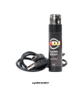
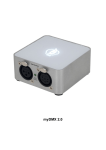
1
USER MANUAL EYESMAP Version 1.0 Revision A June 2015 Contents 1. 2. 3. 4. 5. Introduction .......................................................................................................................... 5 1.1. EyesMap Tablet ............................................................................................................. 6 1.2. How does EyesMap work? ............................................................................................ 7 1.3. Eyesmap Standard Configuration Package.................................................................... 8 Technical Specifications ........................................................................................................ 9 2.1. Tablet........................................................................................................................... 10 2.2. Cameras ....................................................................................................................... 11 2.3. Depth Sensor ............................................................................................................... 11 2.4. GPS .............................................................................................................................. 11 2.5. IMU .............................................................................................................................. 12 Starting up with EyesMap ................................................................................................... 13 3.1. General Security Information ...................................................................................... 14 3.2. Charging the battery ................................................................................................... 14 3.3. Transport ..................................................................................................................... 15 3.4. Power Supply............................................................................................................... 15 3.5. Switching on the tablet ............................................................................................... 15 EyesMap Applications ......................................................................................................... 17 4.1. Main Application Screen ............................................................................................. 18 4.2. Standard Windows and Buttons ................................................................................. 19 4.3. Target Types and Their Use ......................................................................................... 20 EyesMap Modules ............................................................................................................... 22 5.1. Menu ........................................................................................................................... 23 5.1.1. Main Application Screen ..................................................................................... 23 5.1.2. Project Management........................................................................................... 23 5.1.3. Camera Calibration .............................................................................................. 28 5.1.4. Camera Orientation ............................................................................................. 29 5.1.5. Updating/Restoring EyesMap ............................................................................. 31 5.2. Point-to-Point Photogrammetry ................................................................................. 32 5.2.1. Photograph Capture and Management .............................................................. 32 5.2.2. Image Gallery ...................................................................................................... 36 5.2.3. Image Viewer....................................................................................................... 36 5.2.4. Choosing Orientation Mode ................................................................................ 37 5.2.5. Scaling with the StereoTarget ............................................................................. 41 User Manual 2 5.2.6. Point-to-Point Measurement Screen .................................................................. 43 5.2.7. Results Screen and Export of Results .................................................................. 47 5.2.8. Orientation Errors ............................................................................................... 49 5.3. 3D Modelling ............................................................................................................... 50 5.3.1. Photograph Capture and Management .............................................................. 50 5.3.2. Image Gallery ...................................................................................................... 53 5.3.3. Image Viewer....................................................................................................... 53 5.3.4. Model Resolution Screen .................................................................................... 54 5.3.5. stereoTarget Scaling Screen ................................................................................ 56 5.3.6. Master and Secondary Image Selection Screens ................................................ 57 5.3.7. Results Screen ..................................................................................................... 63 5.4. Depth Sensor ............................................................................................................... 65 5.4.1. RGBD Menu ......................................................................................................... 65 5.4.2. Capture a 3D Model ............................................................................................ 66 5.4.3. Post-Processing Software .................................................................................... 71 5.4.4. 3D Viewer ............................................................................................................ 77 5.5. Orthophoto ................................................................................................................. 78 5.5.1. Photo Development and Management Screen ................................................... 78 5.5.2. Image Gallery ...................................................................................................... 81 5.5.3. Image Viewer....................................................................................................... 81 5.5.4. Final Results Quality Selection Screen ................................................................ 82 5.5.5. Projection Plane Selection Screen ....................................................................... 84 5.5.6. Screen for Indicating the Projecting Plane on the Image .................................... 84 5.5.7. Image Selection Screen to Choose the Control Points and the Reference Points on the X Axis ........................................................................................................................ 86 5.5.8. Control Points and Reference Points on Axis X Selection Screen ....................... 87 5.5.9. Additional Image Selection Screen to Choose more Control Points and more Reference Points on the X Axis ........................................................................................... 90 5.6. 6. GPS .............................................................................................................................. 92 5.6.1. Protocols.............................................................................................................. 92 5.6.2. COM Port Properties and Changing COM Port ................................................... 93 5.6.3. Real-Time Data Screen ........................................................................................ 96 5.6.4. Change Protocol .................................................................................................. 98 5.6.5. Post-Processing ................................................................................................. 102 Viewers .............................................................................................................................. 108 User Manual 3 7. 6.1. MeshLab Touch ......................................................................................................... 109 6.2. Filters ......................................................................................................................... 111 6.2.1. Remove Outliers ................................................................................................ 111 6.2.2. Create Mesh ...................................................................................................... 112 6.2.3. Clean Noise ........................................................................................................ 114 Practical Cases ................................................................................................................... 116 7.1. 8. Point-to-Point Photogrammetry ............................................................................... 117 7.1.1. Methodology ..................................................................................................... 117 7.1.2. Orientation with Targets. .................................................................................. 139 7.1.3. Use of Targets.................................................................................................... 146 7.2. 3D Photomodelling.................................................................................................... 151 7.3. Depth Sensor ............................................................................................................. 161 7.4. Orthophoto ............................................................................................................... 168 7.5. GPS ............................................................................................................................ 181 Orientation Errors ............................................................................................................. 192 User Manual 4 1 1. Introduction In this chapter, we shall see: EyesMap Tablet How does Eyesmap work? Eyesmap Standard Configuration User Manual 5 1 Introduction This document describes the detailed operation of the Eyesmap Tablet for each individual module and feature. It intends to be a guide explaining the use of the different modules, for you to get the best out of your Eyesmap tablet. This manual will help you how best to capture 3D data in the field in order to obtain the best final results possible. 1.1. EyesMap Tablet EyesMap is a High Capacity Tablet PC that allows measurement, 3D modelling and documentation of the environment around us. This measurement device, with its two integrated and calibrated HR cameras, is based on photogrammetry, and in addition relies on other sensors to capture detailed 3D models of the environment and complex 3D geometric objects quickly and conveniently. The results obtained by this tablet are 3D models of both small objects, as well as midsized and big objects containing millions of points. It allows real-time measurement of coordinates, distances and surfaces and generation of real orthophotos. All these results can be positioned geographically in real time thanks to the integrated GPS. High Processing Capacity Simple and intuitive Interface High mobility due to the portability and light weight of the device Attractive and ergonomic design High connectivity through USB, Micro SD and HDMI. User Manual Speed High Resolution 3D models generated. Integrated inertal system Integrated GPS High speed data communication through WLAN and 3G. 6 1 Introduction 1.2. How does EyesMap work? The measurement modules and the 3D Photo modelling are based on photogrammetric techniques. Photogrammetry is a technique to determine the geometric properties of an object from photographic images. By orienting the different captured images of an object we can create stereoscopic view, allowing the generation of 3-dimensional information. In the following image the position of the cameras is displayed. For 3D modelling indoors, the use of the depth sensor is recommended. This sensor is projector of infrared points combined with a CMOS sensor allowing to capture the environment in 3D in any light conditions. The useful detection range of the depth sensor is up to 4 meter. In the following image the position of the depth sensor is displayed. The obtained 3D results can be geo-referenced real-time through the integrated GPS at a best accuracy of 0.6m. If higher absolute precision is required, the – at least 10 minutes- collected data can be post-processed up to a best accuracy of 0.10m. The integrated inertial system comprises a gyroscope, an accelerometer and a magnetometer, which provides us information of the tablet 3D movement speed, orientation and gravitation forces in real-time. User Manual 7 1 Introduction 1.3. Eyesmap Standard Configuration Package The Eyesmap package comes as standard in the following configuration: 4 3 6 2 5 1 1. 2. 3. 4. 5. 6. Transport Case Tablet AC charger and Cable (Euro plug) GPS Antenna Keyboard Set of Targets existing of: a. 40 symmetric Point Targets b. 20 Asymmetric Targets c. 1 Stereo Target for small objects d. 1 Stereo Target for big objects User Manual 8 2 2. Technical Specifications In this chapter, we shall see: Tablet Cameras Depth Sensor GPS IMU 2 Technical Specifications 2.1. Tablet Find below the technical specifications of the main components of the Eyesmap Tablet. User Manual 10 2 Technical Specifications 2.2. Cameras Number of cameras: 2 Base Line Length: 230 mm Field of View: 67º (Diagonal) Focusing distance: 2.8 mm Pixel size: 1.4um x 1.4um Depth of field: 10 cm Optical distortion, Interior exterior orientation: Yes 2.3. & Depth Sensor Typical precision: 1,5mm@1m 2,2mm@2m 30mm@3m (Post-processing) : 2-3mm@2m Maximum scanning range in motion: Unlimited Maximum depth scanning distance: < 6 m 2.4. Cameras Calibration: < 1 px Calibration stability: 2 px Calibration of other sensors vs. Cameras: Yes Manual and Auto Focus Macro Digital Stabilizer Post-processing time: > 3 min. Depends on total scanning time and complexity of the section scanned. Export Formats: Ascii, .DXF, .pts, .ply, .xyz, .csv, .las, .PN, .PV, .obj GPS L1 – Single Frequency GPS, GLONASS, GALILEO, QZSS, COMPASS & SBAS L1 Nr. Of Channels: 32 GNSS Data output w/o processing: pseudo-distance, Carrier Phase and Doppler. User Manual Data Protocols: NMEA 0183 / IEC 61162-1, binary (BINR) and RTCM SC-104 Typical precisions Real Time: 1.5 m aprox. Post-processing: 30 cm aprox. (at 10 minutes of field data capture) 11 2 Technical Specifications 2.5. IMU Acelerometer Gyroscope Acceleration Measurement Max Acceleration Measurement Resolution Accelerometer White Noise σ Accelerometer Minimum Drift σ Accelerometer Optimal Averaging Period ±8g 976.7 μg 2.8 mg 1.9 mg 286 s Gyroscope Speed Max Gyroscope Resolution Gyroscope White Noise σ Gryoscope Minimum Drift σ Gyroscope Optimal Averaging Period ± 2000°/s 0.07°/s 0.59°/s 0.0019°/s 8628 s Compass Magnetic Field Max 5.5 G Compass Resolution 3 mG Compass White Noise σ 1.2 mG Compass Minimum Drift σ 87 μG Compass Optimal Averaging 52 s Period User Manual 12 3 3. Starting up with EyesMap In this chapter you will find: General Security Information Charging the battery Transport Power Supply Switching on the tablet 3 Starting up with EyesMap Read this manual carefully before starting to use Eyesmap. Refer to this content when necesary. Pay attention to the following instructions and follow them step by step. 3.1. General Security Information The maintenance and repair of the Eyesmap Tablet can only be done by qualified personnel authorized by e-Capture. Contact authorized service personnel in the following situations: The power cable is damaged. The Tablet has been exposed to rain, water or other liquids. The Tablet has been dropped or damaged. The Tablet does not work normally when following the operating instructions. Do not expose the Tablet to extreme temperatures. Do not use the Tablet near to artificial heating sources. Do not use the Tablet in strong magnetic or electric field areas. Do not submerge the Tablet in water. Consult your authorized dealer or [email protected] for any questions or doubts you may have. 3.2. Charging the battery The following safety precautions must be taken when using the Tablet with power cable connected: Only use the charger as provided by e-Capture to charge the battery. Don not charge the Tablet when it is stored in the carrying case. It is recommended to charge the battery at temperatures between 5ºC (41°F) and 35ºC (95°F). To charge the battery, connect the charging cable plug to the DC IN input port of the Tablet. User Manual 14 3 Starting up with EyesMap 3.3. Transport When transporting the Tablet, be careful not to drop it. A strong impact may damage the unit and cause malfunctioning of the scanning function. Always transport the Tablet in its original carrying case.. When shipping EyesMap by any means of transport, please make sure to use the original shipping case and to place all components correctly, to avoid possible shock and vibration. Keep the tablet switched off during transport in the carrying case. 3.4. Power Supply If you are storing the tablet for a long period of time, be sure NOT to leave the battery completely discharged. Make sure the tablet is stored clean and in its original case. Keep all components in a low-humidity environment. The stored device shall be not subject to extreme temperatures. 3.5. Switching on the tablet To start using the Eyesmap Tablet for the first time, press the ON/OFF switch located on top of the Tablet. Both the Microsoft Windows 8.1 Operating System and the other software required to run the Eyesmap Tablet properly have been pre-installed by the Manufacturer. As a registered user of Eyesmap, you are officially licensed to update the device with the latest Windows security enhancements and functionality. User Manual 15 3 Starting up with EyesMap A variety of software programs are included as standard in Eyesmap to perform your everyday tasks and data processing: Eyesmap Software Internet explorer Meshlab Daemon tools lite. Microsoft Visual Studio 2008,2010 and 2012. NotePad++ Winrar Drivers of all the components installed Etc. Once when switched on the Tablet, you can start using the application by pressing the main Eyesmap application icon (1), or activating the visualizer (2), or by opening the project directories (3). 1 2 User Manual 3 16 4 4. EyesMap Applications In this chapter, we shall see: Main Application Screen Text Windows and Standard Buttons Types of Targets and How to Use Them 4 EyesMap Applications In this chapter, the tablet’s main application screen shall be explained, as well as the different buttons which are common to all modules. 4.1. Main Application Screen When you start the “EyesMap” application, the main menu appears. The available modules can be selected from this menu. With this intuitive interface, you can take measurements, generate 3D models, create orthophotos, use the GPS and manage the projects you undertake. The application is made up of 8 modules: The first 3 modules are for point-to-point photogrammetry for the measuring of coordinates, distances and surfaces. 3D Photomodelling: this is the module used for creating 3D models with photogrammetric methods using the stereo cameras. 3D Depth Sensor: Generation of a 3D point cloud using the depth sensor. Best for close-up use (max. 4 metres) and interiors. Especially useful for homogeneous surfaces which do not have texture. Orthophoto: Generation of orthophotos which allow images of objects to be created with orthogonal projection. This is very useful for architectural and archaeological applications. GPS: This module allows for the absolute positioning of the tablet´s coordinates in real time. The post-processing module can also be used to improve accuracy. Menu: This module allows you to manage projects, update the application and calibrate and orient the cameras. User Manual 18 4 EyesMap Applications 4.2. Standard Windows and Buttons The application has navigation buttons which will allow you to move with ease through the available features and tools. Click to minimise the application. Click to close the application. Before closing the application definitively, you will be asked if you want to save the work you have done or if you wish to exit without saving. All running processes will be stopped. Click to go to the next screen or return to the previous screen. Find the location of these icons on the following image: User Manual 19 4 EyesMap Applications This image indicates that the application is processing data. Please be patient as, depending on the process, it may take several minutes. Information Boxes These boxes provide additional information which can be of help for you in the different steps that you must follow. 4.3. Target Types and Their Use A target is a piece of paper, cardboard or another material on which a code is written in black and white and which is detected by the system automatically in the images taken. The targets identified provide information for the orientation of images, measuring of points or scaling of 3D models, depending on the case. stereoTarget for Medium and Large Objects (59 cm) 59 cm This stereoTarget (the larger of the two) is used to scale the measurements taken (point-to-point photogrammetry module) and for scaling 3D models made with photogrammetry (3D photomodelling module). It is used solely for medium and large objects. While it is not necessary for the stereo target to appear in all photographs, it is recommendable for it to appear in as many images as possible so that scaling is more accurate. User Manual 20 4 EyesMap Applications In addition, scaling can also be undertaken manually without the use of the stereoTarget. See at chapter 5.1.4. StereoTarget for Small Objects (15 cm) 15 cm This stereoTarget is used to scale the measurements taken (point-to-point photogrammetry module) and for scaling 3D models made with photogrammetry (3D photomodelling module). It is used solely for small objects. While it is not necessary for the stereo target to appear in all photographs, it is recommendable for it to appear in as many images as possible so that scaling is more accurate. Asymmetric Targets Sample of Asymmetric different ones in total) Targets (20 Targets (40 in total) Asymmetric Targets and Targets work together in order to: Carry out automatic orientation with Targets photogrammetry module. in the point-to-point Carry out orientation of the stereo cameras in the orientation module. Take precise measurements in the point-to-point photogrammetry module. User Manual 21 5. EyesMap Modules 5 In this chapter, we shall see: Menu o Main Application Screen o Project Management o Camera Calibration o Camera Orientation o Updating/Restoring EyesMap Point-to-Point Photogrammetry o Photograph Capture and Management o Choosing Orientation o Scaling with the StereoTarget o Point-to-Point Measurement Screen o Results Screen and Export of Results 3D Modelling o Photograph Capture and Management o Model Resolution Screen o stereoTarget Scaling Screen o Master and Secondary Image Selection Screens o Results Screen Depth Sensor o RGBD Menu o Capture a 3D Model o Post-Processing o 3D Viewer Orthophoto o Photo Development and Management Screen o Final Results Quality Selection Screen o Projection Plane Selection Screen o Screen for Indicating the Projecting Plane on the Image o Image Selection Screen to Choose the Control Points and the Reference Points on the X Axis o Control Points and Reference Points on Axis X Selection Screen o Additional Image Selection Screen to Choose more Control Points and more Reference Points on the X Axis GPS o Protocols o COM Port Properties and Changing COM Port o Real-Time Data Screen o Change Protocol o Post-Processing 5 EyesMap Modules 5.1. Menu This module allows the user to manage the application's projects and to calibrate and orient the cameras. In addition, through this module, the user can access the software's automatic update function. Click on this icon to go to the menu's main screen. 5.1.1. Main Application Screen The four management options are found on the main screen of the module. By clicking on any of the four options, you can access the corresponding actions related with each one. 5.1.2. Project Management The location designated for storage of projects is the directory EyesMapProject in C:\. The structure of projects inside EyesMapProject is a main directory (ProjectName) which includes various subdirectories (3D, 3DDepth, GPS, etc.) where all processes carried out in the project shall be stored. User Manual 23 5 EyesMap Modules When you begin to work with the application, the name of the project is set as “temp” by default; thus, all processes undertaken are automatically stored in the directory C:/EyesMapProject/temp. Click on this button to save the temporary project with another name, create a new project or load an existing project. When you select the project management option, the application shows the main screen where the three available actions appear: create a new project, load an existing project and save the current project. New Project Click to create a new project. You can select an existing folder which is empty or create a new one (in both cases, the name of the directory CANNOT be called “temp”). Everything processed in the new project which has been created will be saved automatically in the selected/created directory using the project structure that was mentioned previously. User Manual 24 5 EyesMap Modules Load Project Click to load an existing project and work on it. Everything processed in the loaded project will be saved automatically. To load the project, you should select the folder with the project name and click OK. Save Project It is important to remember that the EyesMap system automatically saves all the processes undertaken, except the measurements taken by the point-to-point photogrammetry module, in which case results must be exported in the desired format. The option “Save Project” has two different behaviours depending on the type of project in question. If the current project is a temporary project (the application has been started and the project has not been saved with any name), this option will save the current project with the name you choose. If the current project is a project which was already generated and already has a name (not a temporary project), this option will save an exact copy of the project and the application will continue working with this new copy which has been generated. Therefore, this tool can be used to save a project for the first time or to create a copy of another project. You must keep in mind that when you are working with a project which has already been loaded (not a temporary project), changes are saved automatically. User Manual 25 5 EyesMap Modules 5.1.2.1. Project Management when Opening EyesMap If, while using EyesMap with a temporary project, the application closes unexpectedly, it is possible to recuperate the temporary project that you were working on. When the application opens again, the temporary project recuperation screen will appear, in which it will be possible to recuperate the project that you were working on, or begin a new one. Load Project Click to load the temporary project that you were working on. New Project Click to discard the project that you were working on and create a new project. User Manual 26 5 EyesMap Modules 5.1.2.2. Project Management when Closing EyesMap After clicking on the “Close” button, a screen with two options will appear: “Save Project” and “Exit Application.” This is a dynamic screen in which the save option will vary depending on the current project. If it is a temporary project, the application will ask you if you want to save the temporary project or not. Likewise, if you have been working on a loaded project, the application will inform you that the changes have been saved automatically, allowing the user to save a copy of the project. Save Project The project will be saved with the assigned name within the directory C:\EyesMapProject. Exit Click to exit the application. If the current project is a temporary project, it will be eliminated upon exiting the application. If it's a loaded project, the changes made will be saved automatically. User Manual 27 5 EyesMap Modules 5.1.3. Camera Calibration Camera calibration is the most important step so that 3D reconstruction processes and precise measurements can be carried out. To calibrate a camera means to find the internal and external parameters, as well as possible distortions. The better the calibration of the cameras is, the greater the accuracy will be in the models and measurements obtained. For storage of calibrations carried out, a “Calibrations” directory has been created at C:\EyesMapProject\AutoCalibration. All EyesMap devices have a default calibration configuration, obtained in an optimal way and called calDefault. It is highly recommended not to delete said calibration configuration under any circumstances and to use said configuration preferentially. Check with [email protected] for more information on new calibration configurations. Click this option to manage camera calibration. When you select the camera calibration option, the application shows the main screen where the two available actions appear: calibrate cameras and load calibration. User Manual 28 5 EyesMap Modules Calibration Click to calibrate the EyesMap cameras. To complete this action, consult [email protected]. Load Calibration Click to load one of the calibration configurations stored in the directory “Calibrations.” Remember that you must select the folder whose name matches the name which was assigned when calibration was carried out. 5.1.4. Camera Orientation In order to be able to reconstruct an object in 3D based on a pair of images, it is necessary to know the position of said still images in space. This is known as the “external orientation of a pair” and it represents the angular position and orientation associated with the pair of images. The orientation defined here shall only be used if, to take measurements with EyesMap, only one pair of images has been used and stereoTarget has not been used to scale the model. In any other case, EyesMap will calculate the external orientation of the images in situ. For storage of orientation, an “Orientations” directory has been created at C:\EyesMapProject\AutoOrientation. All EyesMap devices have a default orientation, called oriDefault, obtained in an optimal way (using targets) for situations in which the capturing of objects to be measured is carried out from an approximate distance of 3 metres. Click to manage the external orientation of the cameras. User Manual 29 5 EyesMap Modules When you select the camera orientation option, the application shows the main screen where the two available options appear: set orientation of cameras and load orientation. Orientation Click to set camera orientation. To complete this action, consult [email protected]. Load Orientation Click to load one of the orientation configurations stored in the directory “Orientations.” Remember that you must select the folder whose name matches the name which was assigned when orientation was carried out. User Manual 30 5 EyesMap Modules 5.1.5. Updating/Restoring EyesMap EyesMap has an automatic online update module to obtain, easily and quickly, any patches and new features that have been developed for the application. Click to launch the automatic update module of EyesMap when you are connected to a wireless network. When you select this option, the update and restore module shall launch and the EyesMap application will close. Update In order to update the software, you must have an internet connection. Once the module has detected the software version installed on the device, it will tell you if it is necessary or not to update with the message "new software updates are available" or, if the device is already up to date, you will see the following message: "You have the latest version! Update is not required." Depending upon the size of the update and the bandwidth available from the internet connection used, the update process can take several minutes. Once the process has finished, the message "update installed successfully" will appear. At this time, you can close the update module and open EyesMap again. User Manual 31 5 EyesMap Modules Backup Copy Every time that you update the software, before this process starts, a backup copy of the current version is made so that if the update fails for any reason, the last version of EyesMap installed on the device can be restored. If this icon is shaded out in grey, it means that a backup copy does not exist. Under normal conditions, this will only occur if the update process has not been run. 5.2. Point-to-Point Photogrammetry With the point-to-point photogrammetry module, we can obtain, using the captured images, three-dimensional coordinates, distances and surfaces formed by different points. For the purpose of simplicity and clarity, the main menu of this module has been broken down into three buttons: coordinate, distance and surface. The three bring you to the same point-to-point photogrammetry window (where all the options are available again), but with the added advantage that the tool chosen in the main menu is already selected in the secondary window. 5.2.1. Photograph Capture and Management After selecting any of the three options of the point-to-point module, the “Image Capture and Management” window is shown. Here, the first thing that you should do is choose the photograph capture or load mode. User Manual 32 5 EyesMap Modules You have three options: Single Camera Take all the shots with a single camera. Stereo Camera Click if you wish to activate both cameras. Load Images Click if you wish to load previously-captured images. If you choose the option to activate the Stereo Camera, EyesMap will display the following screen: User Manual 33 5 EyesMap Modules At this step, you must take three photographs which shall be used for the entire process. In all photogrammetric captures, the following considerations should be taken into account: Take clear photos, try not to move while you are capturing. Avoid the sun facing you. Capture the entire object to be measured, try to place said object in the centre of the image. Take different shots from the left to the right of the object, from the right to the left, from the top to the bottom or from the bottom to the top. Try to have displacement between the shots (never take two shots from the same position). The overlapping area between the two images should be 80%. If this overlapping can get to be almost 100%, it would be better for improved orientation. Not all objects are good for photogrammetry: for example, areas with a very homogeneous texture like walls painted a single colour, plastic or glass objects or water are not good for photogrammetry as the system has trouble finding common points in the images due to reflection. Whenever possible, we recommend taking photographs as perpendicularly to the object as possible. This shall eliminate noise in the 3D model. Even so, in certain cases with difficult textures, like glass or white walls, it is possible to carry out point-to-point photogrammetry. In this case, you can use manual orientation or automatic orientation with targets. At minimum, 2 photographs should be taken. It is important to review each one of them to delete those which are poorly-focused, poorly-lighted or blurry (accuracy can go down notably). Remember that you can modify the properties of each camera, adjusting them to the light conditions which exist at the time of the shot. It is important for there not to be significant differences between the two cameras. User Manual 34 5 EyesMap Modules In the photograph capture and management window, you will find the following buttons: Take Photographs Click to take photographs. Load Images Click to load existing images. The images must have been captured with the EyesMap cameras. Discard Images Select the photographs in the photo gallery and click to discard. Click to change the camera's settings. User Manual 35 5 EyesMap Modules 5.2.2. Image Gallery At the bottom part of the window, the gallery of loaded or captured images can be seen. This is a touch-controlled gallery in which the new images which are loaded or captured are added to the right of the previous ones. Initially, the button to discard images is not visible. This button only becomes visible when at least one image is selected to be erased. To select or de-select one or several images, you only have to click once on them. The selected images stand out from the rest because a black frame appears around them. 5.2.3. Image Viewer To see the larger version of the image, you can double click on the gallery thumbnail. In this way, the image shall be shown in the viewer, where you can: Zoom the photograph (lower left image). Restore zoom with a double click (lower right image). Delete the image by clicking the "Discard Image" button. Go forward and backward through the images with touch movements, as has been explained with the gallery. Zoom the Photograph User Manual Restore Zoom 36 5 EyesMap Modules 5.2.4. Choosing Orientation Mode EyesMap has three methods to orient images: automatic, manual and with automatic target detection. 5.2.4.1. Automatic Orientation Carry out orientation of images automatically by matching of the homologous points found. Of the three types of orientation, this one is the most automatic and the quickest. It can be used in practically all circumstances, provided that the object or surroundings captured has heterogeneous surfaces. It is not advisable to use this orientation mode on homogeneous surfaces, walls of a single colour, glass or exposed brick where the search for common points may be difficult. User Manual 37 5 EyesMap Modules 5.2.4.2. Manual Orientation You can manually carry out orientation of images. With adjacent images, you must select at least 9 points distributed throughout the image (see the graphic). Points shall be identified as “opX” (Orientation Point X). The greater the number of points you select, the more robust and accurate your orientation will be. As can be seen in the previous graphic, between images 1-2 and 2-3 there are, at least, 9 points in common. Areas not in common can have fewer points, if desired, in order to complete orientation on all parts of the image. This orientation method has the drawback of being manual and requiring the selection of at least nine points, thus increasing the time required for the work. On the other hand, it has the advantage of accuracy and flexibility in point selection. 5.2.4.2.1. Selection of Orientation Points For the selection of orientation points, EyesMap displays the screen shown in the image below. The process cannot be advanced until at least 9 points on the image have been selected. User Manual 38 5 EyesMap Modules The tools included in the interface are the following: Orientation Point Allows you to select an orientation point by double clicking on the image. This button is activated by default. Confirm Click to confirm an orientation point which has been selected. Scale If scaling has not been carried out with the stereoTarget, or you wish to scale with a real distance which is known, you can use the “Scale” tool. You should input the real measurement of the distance and then select the two points which make up the distance. This tool is treated with priority over the stereoTarget scaling. Automatic search for homologous points. Looking for homologous points in all images. This option is selected by default and it searches for the orientation point that was selected in one image in the rest of the images. If the point is not found, it shows the images in which said point has not been found so that it can be marked manually. Add automatic orientation points. Add automatic matching points to orientation. User Manual If you select this option (de-selected by default), the points found with automatic orientation will be added to your manual orientation so that both orientation methods are combined. This has the advantage of increasing orientation points, but orientation accuracy can decrease depending upon the quality of the shot. 39 5 EyesMap Modules 5.2.4.3. Automatic Orientation with Targets This carries out orientation of images automatically by paring targets recognised. Of the three types of orientation, this is the one which provides the best accuracy, but it also requires more processing time. Like manual orientation, it is necessary for there to be at least 9 “symmetrical” targets in common between consecutive images, with areas not in common being able to be completed with the number of targets you wish. As can be seen in the previous graphic, between images 1-2 and 2-3 there are, at least, 9 symmetrical targets in common. 5.2.4.3.1. Methodology for Orientation with Targets To carry out orientation with targets, it is necessary to take the following considerations into account: Between contiguous photographs there should be at least 3 asymmetrical targets in common. This type of target is not used as an orientation point but instead it is used as a pairing tool for the symmetrical targets. As has already been explained, there should also be at least 9 symmetrical targets in common. The following images show a pair of photo captures in which 6 asymmetrical targets and 16 symmetrical targets are recognised to be in common. User Manual 40 5 EyesMap Modules In addition to being used as orientation points, EyesMap will supply the threedimensional coordinates of the symmetrical targets' centre points. 5.2.5. Scaling with the StereoTarget On this screen, you must specify if you wish to use the stereoTarget to scale the results or not. Remember that if you do not use the stereoTarget, you can always scale the results using a real measurement. User Manual 41 5 EyesMap Modules No Click if you have not used the stereoTarget or you do not wish to scale the image with the stereoTarget. Si Click if you wish to scale with the stereoTarget. Two new groups of options will appear: Type of stereoTarget used: large (selected by default) or small. Search in all images (selected by default) or choose the images in which the stereoTarget should be looked for. If the stereoTarget appears in all images, select the first option. Otherwise, select the second option and choose the images in which the search should be carried out (at least two images). This second option shall be useful, above all, in lineal captures in which the stereoTarget appears in only some of the photographs. In this way, we avoid the processing time used for unnecessary automatic searching of images. User Manual 42 5 EyesMap Modules EyesMap may require help in searching for the stereoTarget, asking the user to select the points manually. This may happen in the following situations: If only 2 photographs have been taken and the stereoTarget has not been detected in one of them, or in neither of them. If more than 2 photographs have been taken and the stereoTarget has not been detected in at least 3 of them. If the stereoTarget is automatically recognised, a cross appears in the centre of each target which makes it up. When performing manual selection, it is recommendable to mark one of the corners in one of the squares and the same corner in the next square (as shown in the image), as manually marking the centre of the target with accuracy is quite difficult. 5.2.6. Point-to-Point Measurement Screen Once the photographs have been captured and the capture, orientation and scaling modes have been selected, EyesMap displays the point-to-point measuring screen in which you can obtain the coordinates, distances and surfaces of any object or environment captured. User Manual 43 5 EyesMap Modules It is not necessary to select all points in the same photograph, although it is recommendable. You can move through the different photographs by simply selecting them in the image gallery at the bottom of the screen. If you have used the stereoTarget for scaling, check that it has been correctly detected in the corresponding images (a cross is displayed in the centre of the detected target). Remember that you can also do scaling with the “Scale” tool. The tools available in this screen are the following: Coordinate Measurement Select this if you wish to obtain the three-dimensional coordinate of a point. To make your selection, you must first double click on the point in the image and then click on confirm. Distance Measurement Select this if you wish to measure the distance between two points. Once you have activated this option, you must select each one of the two points as if they were simple coordinates. User Manual 44 5 EyesMap Modules Surface Area Measurement Choose this option if you wish to obtain the area of a surface. You must choose, as if they were simple coordinates, both points and vertices which make up the desired surface. As you are selecting points, you will see the surface formed being drawn on the image. Click finish to close the surface. IMPORTANT: select points in a clockwise or counter-clockwise direction, NEVER randomly. Target Recognition Choose this option to automatically recognise targets. Consult section 3.4.2.3.3 to carry this process out correctly. Identifier By default, simple coordinates are assigned the identifier pX (with X being the point number), distances are given the identifier dX and surfaces are assigned the identifier sX. You may include your own identifier or code for each coordinate, distance or surface by introducing the desired code in this field before confirming the point. Confirm Click to confirm an orientation point which has been selected. Automatic search for homologous points. Look for homologous The value input in this property is the number of images points in this number of adjacent to the one where we selected the point. In said number adjacent images. of images, the search for homologous points shall be carried out. In the following examples, the image where the point has been selected is represented in green. The search images are represented in blue, for a value of 2 in this property. The minimum value is 1. User Manual 45 5 EyesMap Modules * Definition of homologous points: between two consecutive images (A and B) with a large common area, two homologous points are those points that represent an object that the two images have in common (a common corner or frame between images A and B). Selection Tool To delete an element, it must first be selected. Choose this tool to select the area where the elements which you wish to delete are located and drag your finger over the screen to draw the desired area. The elements which are inside the selected area will turn yellow. You must keep in mind that, if you select a point of a distance or surface, the entire surface or distance will be selected. You can remove your selection by clicking on the selection tool again. User Manual 46 5 EyesMap Modules Deletion Tool Click to delete the selected elements. Stretch Image Tool Click to stretch the image to the size of the screen after having zoomed in on a part of the image. Scale If scaling has not been carried out with the stereoTarget, or you wish to scale with a real distance which is known, you can use the “Scale” tool. You should input the real measurement of the distance and then select the two points which make up the distance. This tool is treated with priority over the stereoTarget scaling. 5.2.7. Results Screen and Export of Results After processing the data, EyesMap shows the results of the coordinates, distances and surfaces calculated. Results can be seen in all images, as well as in the results box located to the right of the screen. User Manual 47 5 EyesMap Modules Results Box In the results box, the data which results from the coordinates, distances and surfaces obtained is displayed by block. This box is flexible and modifiable, like notepad, so that you can make notes on the data obtained so that, for example, the contents and notes can be copied and included in any type of document. Export Tool Click to export the results to other formats (TXT / TXT 3D / JPG / DXF). In the export window, you must choose the file format, its name and the directory where you wish to save it. The characteristics of the different export formats are as follows: TXT Data Results (*.txt): The results are exported to a text file with the same format as that shown in the results box. TXT 3D Coordinates (*.txt): A text file is generated with the three-dimensional coordinates (x, y, z) of each point of the coordinates, distances and surfaces selected, in that order. User Manual 48 5 EyesMap Modules JPG Image (*.jpg): This exports, in JPG format, the image displayed on the results screen. If you wish to export any other image of those used in the process along with the results, you just need to select it in the gallery at the bottom of the screen. DXF CAD (*.dxf): This exports the results in DXF format so that they can be viewed and edited in different external pieces of software. Coordinates shall be saved in the DXF file as points, distances as lines and surfaces as a set of continuous lines. 5.2.8. Orientation Errors During data processing, orientation of images is calculated in situ. If any problems arise, an orientation error is shown which indicates what images have been problematic. You must repeat the process with new images or omit the images listed in the error message. User Manual 49 5 EyesMap Modules 5.3. 3D Modelling EyesMap module which allows for 3D models of objects with small, medium and large sizes to be created. The result obtained shall be a 3D point cloud in colour (in PLY format, containing the X Y X coordinates and the R G B colour). Almost all elements can be modelled except reflective surfaces (glass, water, plastics, etc.) or surfaces with very homogeneous textures. If you want your point clouds to be scaled, you should use the stereoTarget (the small one for small objects, the big one for medium and large objects). 5.3.1. Photograph Capture and Management After selecting the 3D Photomodelling options, the “Image Capture and Management” window is shown. Here, the first thing that you should do is choose the photograph capture or load mode. You have three options: Single Camera Take all the shots with a single camera. Stereo Camera Click if you wish to activate both cameras. Load Images Click if you wish to load previously-captured images. If you choose image capture with the cameras, they activate and are shown on screen. User Manual 50 5 EyesMap Modules At this step, you must take three photographs which shall be used for the entire process. In all photogrammetric captures, the following considerations should be taken into account: Take clear photos, try not to move while you are capturing. Avoid the sun facing you. Capture the entire object to be measured, try to place said object in the centre of the image. Take different shots from the left to the right of the object, from the right to the left, from the top to the bottom or from the bottom to the top. Try to have displacement between the shots (never take two shots from the same position). The overlapping area between the two images should be 80%. If this overlapping can get to be almost 100%, it would be better for improved orientation. Not all objects are good for photogrammetry: for example, areas with a very homogeneous texture like walls painted a single colour, plastic or glass objects or water are not good for photogrammetry as the system has trouble finding common points in the images due to reflection. Whenever possible, we recommend taking photographs as perpendicularly to the object as possible. This shall eliminate noise in the 3D model. Even so, in certain cases with difficult textures, like glass or white walls, it is possible to carry out point-to-point photogrammetry. In this case, you can use manual orientation or automatic orientation with targets. At minimum, 2 photographs should be taken. It is important to review each one of them to delete those which are poorly-focused, poorly-lighted or blurry (accuracy can go down notably). User Manual 51 5 EyesMap Modules Remember that you can modify the properties of each camera, adjusting them to the light conditions which exist at the time of the shot. It is important for there not to be significant differences between the two cameras. In the photograph capture and management window, you will find the following buttons: Take Photographs Click to take photographs. Load Images Click to load existing images. The images must have been captured with the EyesMap cameras. Discard Images Select the photographs in the photo gallery and click to discard. Click to change the camera's settings. User Manual 52 5 EyesMap Modules 5.3.2. Image Gallery At the bottom part of the window, the gallery of loaded or captured images can be seen. This is a touch-controlled gallery in which the new images which are loaded or captured are added to the right of the previous ones. Initially, the button to discard images is not visible. This button only becomes visible when at least one image is selected to be erased. To select or de-select one or several images, you only have to click once on them. The selected images stand out from the rest because a black frame appears around them. 5.3.3. Image Viewer To see the larger version of the image, you can double click on the gallery thumbnail. In this way, the image shall be shown in the viewer, where you can: Zoom the photograph (lower left image). Restore zoom with a double click (lower right image). Delete the image by clicking the "Discard Image" button. Go forward and backward through the images with touch movements, as has been explained with the gallery. Zoom the Photograph User Manual Restore Zoom 53 5 EyesMap Modules 5.3.4. Model Resolution Screen Use this screen to choose the quality of the point cloud that you wish to obtain. EyesMap gives you two options: Option 1: Recommended for less-experienced users. Select the quality of the model which you wish to obtain (high, medium or low). Based upon this choice, EyesMap will select the advanced parameters by default for you. Higher model quality means more points will be included in the point cloud and, in general, the 3D model will be more detailed. On the downside, a higher number of points in the cloud may generate more noise than desired. Likewise, the greater the model's quality is, the greater the processing time will be. This is also true for the size of the PLY file generated. Model Quality Click on a button to choose the quality of the final model (high, medium or low resolution). The high resolution button is selected by default. User Manual 54 5 EyesMap Modules Option 2: Recommended for advanced users. You can manually choose the different parameters related to the quality of the model, provided that you have enough knowledge to do so. Results may be better with correct parameter selection. Advanced Options Click to modify the resolution parameters. Change the point density for the final model. Point Density: The higher the point density you select (high, medium or low), the more points the 3D point cloud generated will have. Keep in mind that a higher point density does not imply better results. An elevated point density can generate undesired noise in some cases. Image Resolution Choose the resolution level (high, medium or low) that you wish to use for the photos taken. High Resolution: 2592 x 1944 Medium Resolution: 1296 x 972 Low Resolution: 648 x 486 We do not recommend lowering image quality. Only do so if you wish to obtain a very basic point cloud. User Manual 55 5 EyesMap Modules 5.3.5. stereoTarget Scaling Screen On this screen, you must specify if you have used the stereoTarget or not and, therefore, if your point cloud will be scaled to a real scale or not. No Click if you have not used the stereoTarget or you do not wish to scale the image with the stereoTarget. Si Click if you wish to scale with the stereoTarget. Two new groups of options will appear: Type of stereoTarget used: large (selected by default) or small. Search in all images (selected by default) or choose the images in which the stereoTarget should be looked for. If the stereoTarget appears in all images, select the first option. Otherwise, select the second option and choose the images in which the search should be carried out (at least two images). This second option shall be useful, above all, in lineal captures in which the stereoTarget appears in only some User Manual 56 5 EyesMap Modules of the photographs. In this way, we avoid the processing time used for unnecessary automatic searching of images. It is necessary for the stereoTarget to appear and be recognised in at least two photographs for the model to be scaled. 5.3.6. Master and Secondary Image Selection Screens Some important concepts to understand this screen follow: Master Image: Everything appearing in the image designated as master shall be modelled in the resulting point cloud. Secondary Images: Images which are assigned to the master image and which help to complete the 3D model. These images should have a lot of overlap with the master image. We do not recommend selecting too many secondary images (no more than 4). Mask: The mask allows you to decide what parts of the master image are modelled and what parts are not. Select only the part(s) which you wish to model. Examples of the selection of master images, secondary images and masks: User Manual 57 5 EyesMap Modules Choose the master and secondary images to create the 3D model. The steps are as follows: 1. Choose a master image. 2. Choose one or several secondary images to complete the master image. 3. Paint a mask over the master image. Said mask shall indicate what part of the master image you want to model (remember, you do not have to model the entire master image if you do not wish to do so). 4. Repeat the process to choose master images if you wish to select more or, if you only need one master image, advance to the next screen. Step 1. Choose a master image (marked in green). Select the image that you wish to set as master and confirm your selection. If you have selected the wrong image, just click on the desired image and the previous image will automatically de-select. Click to confirm the chosen master image. User Manual 58 5 EyesMap Modules Step 2. Choose one or several secondary images to complete the master image (marked in blue). Select the images that you wish to set as secondary. If you have selected the wrong image, just click on it again and it will automatically de-select. It is recommendable to assign one or two secondary images to each master image for each side. Click to confirm the selected secondary images. User Manual 59 5 EyesMap Modules Step 3. Paint a mask over the master image. Draw Sky Click to paint part of the sky in the image. It is not necessary for you to paint the entire sky. Everything will be modelled except for the sky User Manual 60 5 EyesMap Modules Draw Mask Click to paint the part of the image that you wish to model. Select, in white, everything you wish to be modelled in the master image. Draw All Select this to model all the parts of the master image. Type of Brush Select the type of brush that you wish to use (square or round). User Manual 61 5 EyesMap Modules Brush Thickness. Move the sliding bar towards the left or right for greater/less brush thickness. Restore Click to erase everything you have painted/selected on the image. Use this button if you have made a mistake or if you wish to improve your selection. Step 4. Repeat the process to choose more master images or, if you only need one master image, advance to the next screen. Keep in mind that you should select as many master images as you need. User Manual 62 5 EyesMap Modules Box showing the names of the master images and their associated secondary images. You can select images in this list if you wish to delete a master/secondary image from the selection. Delete from the List Select this button to erase the selected images from the list. If you select a master image and delete it, your secondary images and your masks will also be deleted automatically. If you select a secondary image and delete it, the associated master image will be maintained provided that said secondary image was not the only one you had. 5.3.7. Results Screen The screen which shows the final results. If the 3D model has been correctly generated, assign it a name to be saved in the folder Projects/3D/Ply. User Manual 63 5 EyesMap Modules You can automatically go to the folder or keep working and visualise the results when you wish. Example: If you have selected more than one master image and have input the name "example," the names of the point clouds will be, successively, example1, example2, example3, etc. User Manual 64 5 EyesMap Modules 5.4. Depth Sensor This EyesMap module uses the on-board depth sensor to capture scaled 3D models. Because of the device's nature, it is preferably used for interior scans or exterior scans in which sunlight does not directly shine into the sensor. This provides an advantage over photogrammetry as it can capture homogeneous areas and areas with little texture. On the other hand, the accuracy of the point cloud generated is less, with accuracies of less than 1 cm in post-processed data being reached. The capture range must be less than 4 metres. IMPORTANT: The use of the stereoTarget to scale is not necessary; models are already scaled. 5.4.1. RGBD Menu The following image shows the main menu for the depth sensor utilities. User Manual 65 5 EyesMap Modules It has the following 4 buttons: Capture This starts the programme to capture, in real time, 3D models. Post-process This starts the programme to post-process a previously-captured model. 3D Viewer This opens the 3D viewer. Delete Captures This deletes all the actions carried out with the depth sensor in the current project. 5.4.2. Capture a 3D Model When you click on the “Capture” button, the “vSLAM-RGBD RealTime” application opens. This application captures 3D models in real time. 5.4.2.1. Introduction The depth sensor generates a 3D point cloud for each still image (called, from now on, a key frame) and, therefore, the technology aligns all of said images on one coordinate system. The algorithm applied to this type of capture is VisualSLAM. User Manual 66 5 EyesMap Modules VisualSLAM consists of calculating, at all times, the position of the camera (6 degrees of freedom, 3 revolutions to define the location and 3 rotations to define orientation) in an unknown scene based upon the visual information the camera captures. To accomplish this, tracking of a set of visual features (generally characteristic points) is carried out in the succession of images captured by the camera. 5.4.2.2. Workings of the Interface The interface is divided into 4 parts: Application status bar: This allows you to minimise, restore and close the application. Toolbar with available buttons: User Manual 67 5 EyesMap Modules Play When you click on this button, the 3D model is generated. The key frames will be oriented while the capture is being undertaken. IMPORTANT: -To the maximum extent possible, start taking the shot at a heterogeneous area. This will help to improve the results of the entire process. -The binary data which can be post-processed later is automatically saved. -Do not do the capture at a high speed; let EyesMap compute the key frames to properly orient itself. -The data which is automatically saved (and which can be postprocessed) is stored by default in the directory in which you are working, called “sequence_” and followed by the time of capture. -It is recommended not to scan the same surface two times as this noticeably worsens the results. Pause Click to pause the real-time capture process. Click “Play” again to resume capturing. Rotate, move and zoom. User Manual 68 5 EyesMap Modules Closure In the event that you wish to circularly close the capture undertaken, you can click on this button to show the first key frame captured. The aim of this function is to help the user so that he/she closes in the same place where the process started. This button does not do any additional processing – it will only help you to take the sequence of shots correctly and improve postprocessing results. Delete Click to delete the entire real-time capture process undertaken. Once it has been deleted, the screen to start the real-time capture process will be shown again. Save Click to save a point cloud of the current process. Real-time camera viewer: User Manual 69 5 EyesMap Modules Once capturing has begun, the viewer offers you the following information: Indicator of the number of key frames undertaken. The maximum number of key frames that can be processed in one single capture is 400. SLOW This is merely an informational message. It tells you that a new key frame is going to be generated as there is new information in the capture being undertaken. MOVE Informational message which tells the user that he/she has not yet moved enough to generate a new key frame. Point cloud viewer: This shows the 3D model which is being generated. Notice in the following image that the point cloud being displayed is a sub-sample, as each key frame would have around 200,000 points. For the sake of quickness and efficiency, the density of the points viewed in real time is limited. User Manual 70 5 EyesMap Modules 5.4.2.3. What happens if you get lost? The message shown in the previous image, “RECOVERY: point to the last view,” tells the user that the process has not found enough points to pair the last stored key frame with the current image. In order to help with the continuing of the capture, a window appears with the image of the last key frame captured. Try to make the real-time camera image line up with the image of the last correct key frame in order to continue the process. 5.4.3. Post-Processing Software This application allows you to improve a result obtained in real time. Thanks to a high level of data processing, the post-processing application can correct possible orientation errors in the models generated in real time. User Manual 71 5 EyesMap Modules As can be seen in the image above, the interface is divided into 3 parts: Application status bar: This allows you to minimise, restore and close the application. Point cloud viewer: This shows the 3D model which is being post-processed. Information box: this offers information on the process being undertaken. Toolbar with available buttons: User Manual 72 5 EyesMap Modules Compute last Capture This post-processes the sequence of key frames of the last 3D model undertaken in real time. Open Sequence When you click on this button, the following dialogue box opens. Select the saved sequence that you wish to post-process. In the event that the selected directory is incorrect or does not contain a sequence, the following message will be displayed: When you have chosen the correct key frame sequence, post-processing will begin. User Manual 73 5 EyesMap Modules The application buttons will remain inactive while postprocessing is being carried out so that execution errors do not arise. Notice that the information box shows the number of post-processed key frames which have been analysed, and those which remain. Once this message is displayed in the information box, postprocessing has finished. User Manual 74 5 EyesMap Modules Loop Closure In the event that the results obtained are not correct, you can execute this option. Adjust the “Loop Closure Check” bar to execute this algorithm with more or less calculations. The higher this value is, the more probability there is of finding closure, but the process will also take more time. . Save Press this button to save the post-processed key frames. The following files are generated: k0.ply to k7.ply contain each one of the correctly-oriented key frames. Project.aln allows for the opening of the previously-mentioned PLYs with MeshLab. Sampling.ply is a sub-sample of the entire oriented sequence of key frames. The rest of the files contain temporary information which the post-processing application uses for calculations. Do not delete or modify any data. User Manual 75 5 EyesMap Modules Click to view only the representative key frames while postprocessing is undertaken. This saves space in the tablet's memory and the process will end sooner. Change the number of points to be viewed in order to lower computation time. Raw Point Cloud: Shows all the points of all the key frames. Octomap: Shows only select points of each key frame. The level of sampling dictates the level of data processing included in post-processing. The lower this number is, the greater capacity for improvement post-processing will have, but it will take more time. This value is recommended to be set between 5 and 15. Rotation, move and zoom. User Manual 76 5 EyesMap Modules 5.4.4. 3D Viewer Click to open and view a 3D model created with the depth sensor. User Manual 77 5 EyesMap Modules 5.5. Orthophoto EyesMap module for generating true orthophotos. What is an orthophoto? Orthophotography is the photographic presentation of an area in which all elements are of the same scale and the photo is free of errors and deformations, having the same validity as a cartographic map. An orthophoto is acquired through a set of images which have been corrected to create an orthogonal projection without the effects of perspective. Therefore, it is possible to use said orthophoto to take exact measurements, unlike a simple photograph which will always have deformations due to the perspective from the camera, the height of the camera or the speed that the camera is moved at. Therefore, an orthophoto combines the detailed features of a photograph with the geometrical properties of a map. 5.5.1. Photo Development and Management Screen After selecting the orthophoto option, the “Image Capture and Management” window appears. User Manual 78 5 EyesMap Modules At this step, you must take three photographs which shall be used for the entire process. In all photogrammetric captures, the following considerations should be taken into account: Take clear photos, try not to move while you are capturing. Avoid the sun facing you. Capture the entire object to be measured, try to place said object in the centre of the image. Take different shots from the left to the right of the object, from the right to the left, from the top to the bottom or from the bottom to the top. Try to have displacement between the shots (never take two shots from the same position). The overlapping area between the two images should be 80%. If this overlapping can get to be almost 100%, it would be better for improved orientation. Not all objects are good for photogrammetry: for example, areas with a very homogeneous texture like walls painted a single colour, plastic or glass objects or water are not good for photogrammetry as the system has trouble finding common points in the images due to reflection. Whenever possible, we recommend taking photographs as perpendicularly to the object as possible. This shall eliminate noise in the 3D model. Even so, in certain cases with difficult textures, like glass or white walls, it is possible to carry out point-to-point photogrammetry. In this case, you can use manual orientation or automatic orientation with targets. At minimum, 2 photographs should be taken. It is important to review each one of them to delete those which are poorly-focused, poorly-lighted or blurry (accuracy can go down notably). Remember that you can modify the properties of each camera, adjusting them to the light conditions which exist at the time of the shot. It is important for there not to be significant differences between the two cameras. User Manual 79 5 EyesMap Modules In the photograph capture and management window, you will find the following buttons: Take Photographs Click to take photographs. Load Images Click to load existing images. The images must have been captured with the EyesMap cameras. Discard Images Select the photographs in the photo gallery and click to discard. Click to change the camera's settings. User Manual 80 5 EyesMap Modules 5.5.2. Image Gallery At the bottom part of the window, the gallery of loaded or captured images can be seen. This is a touch-controlled gallery in which the new images which are loaded or captured are added to the right of the previous ones. Initially, the button to discard images is not visible. This button only becomes visible when at least one image is selected to be erased. To select or de-select one or several images, you only have to click once on them. The selected images stand out from the rest because a black frame appears around them. 5.5.3. Image Viewer To see the larger version of the image, you can double click on the gallery thumbnail. In this way, the image shall be shown in the viewer, where you can: Zoom the photograph (lower left image). Restore zoom with a double click (lower right image). Delete the image by clicking the "Discard Image" button. Go forward and backward through the images with touch movements, as has been explained with the gallery. Zoom the Photograph User Manual Restore Zoom 81 5 EyesMap Modules Error which appears when a minimum of 4 photographs have not been taken. 5.5.4. Final Results Quality Selection Screen Screen which allows you to choose the quality of the final orthophoto. This will directly influence results. Option 1: Take the orthophoto in high resolution. Recommended for less-experienced users. High Resolution This button is selected by defect and indicates that the orthophoto shall be high resolution. User Manual 82 5 EyesMap Modules Option 2: Advanced options. Recommended for advanced users. You can manually choose the different parameters related to the quality of the model, provided that you have enough knowledge to do so. Results may be better with correct parameter selection. Advanced Options Click to modify the resolution parameters. If this is not clicked, the model will be high resolution. Change the point density for the final model. The higher the point density you select (high, medium or low), the more points the 3D point cloud generated will have. Keep in mind that a higher point density does not imply better results. An elevated point density can generate undesired noise in some cases. User Manual 83 5 EyesMap Modules 5.5.5. Projection Plane Selection Screen What is a projection plane? A projection plane is the plane onto which the model's elements will be projected orthogonally and, therefore, it must be defined by the user. To define it, follow the following steps: Select the image to define the projection plan, clicking on the desired image. The image will turn green. If you selected the wrong image, just click the desired image and the previous image will automatically deselect. 5.5.6. Screen for Indicating the Projecting Plane on the Image Use the paintbrush to paint the plane you wish to use. All elements shall be projected onto that plane when the orthophoto is generated. User Manual 84 5 EyesMap Modules Be especially careful not to paint more than one plane as, in this case, the application can fail or the orthophoto may not be correctly generated. Choose the type of brush: square or round. Brush thickness: move the sliding bar towards the left or right for greater/less brush thickness. Restore Click to erase everything you have painted/selected on the image. Use this button if you have made a mistake or if you wish to improve your selection. User Manual 85 5 EyesMap Modules 5.5.7. Image Selection Screen to Choose the Control Points and the Reference Points on the X Axis Double click on the image you would like to use to set the control points and X axis reference points. - Control Points: These are the 3D points which assist the system in the generation of orthophotos. It is important to define plenty of control points, being distributed throughout the entire scene which is to be calculated (emphasising the upper and lower areas); it is also important to mark the control points on different planes, if they exist. Control points distributed over an image. User Manual 86 5 EyesMap Modules - Reference Points on the X Axis mark the model's horizon line. This shall be defined with two 3D coordinates. Reference Points on the X Axis 5.5.8. Control Points and Reference Points on Axis X Selection Screen You can select the points on the image chosen and/or on the two adjacent images (left and right). For a point to be confirmed, it must appear in at least two of the three images. At minimum, 4 control points should be selected (distributed throughout all the images) and 2 points should be selected to define the X axis (distributed throughout all the images). You can move through the different photographs by simply selecting them in the image gallery at the bottom of the screen. User Manual 87 5 EyesMap Modules Control Points Click to assign control points (this button is selected by default). Double click to choose the image's control points. Confirm the point when you are ready to do so. Reference Points on the X Axis Two points must be chosen to mark the reference points on the X axis. Double click to choose the first reference point on the X axis and confirm it. Next, select the second reference point on the X axis and confirm it. You can select reference points on the X axis in different images. Confirm Click to confirm an orientation point which has been selected. Discard Image This is useful when you confirm a point on one image (control point, reference point on the X axis) and its match does not appear in the remaining images, or if you simply do not wish to mark it (to increase accuracy, we recommend you mark it if it appears). In this case, discard the image in which the homologous point does not appear. Said point will be confirmed in the other images in which it does appear, provided that it appears in at least 2, and it will be discarded if it only appears in 1 image. User Manual 88 5 EyesMap Modules Automatic find matching points. Look for homologous points in this number of adjacent images Looking for matching point. The application is looking for the matching point in the other photographs. It is recommended not to undertake any other actions while this process is being carried out. Selection Tool To delete an element, it must first be selected. Choose this tool to select the area where the elements which you wish to delete are located and drag your finger over the screen to draw the desired area. The elements which are inside the selected area will turn yellow. You must keep in mind that, if you select a point of a distance or surface, the entire surface or distance will be selected. You can remove your selection by clicking on the selection tool again. Deletion Tool Click to delete the selected elements. Stretch Image Tool Click to stretch the image to the size of the screen after having zoomed in on a part of the image. User Manual 89 5 EyesMap Modules 5.5.9. Additional Image Selection Screen to Choose more Control Points and more Reference Points on the X Axis Once you have chosen the points in an image, you can (and it is very recommendable to do so) choose more points on other images. You will return to screen 3.6.6 for choosing control points and reference points on the X Axis for the other selected images. If you do not wish to set more points on other images and you have assigned the minimum number of points required (4 control points and 2 reference points on the X Axis), click on the icon to begin generating the orthophoto. User Manual 90 5 EyesMap Modules 5.5.9.1. Error with Control Points or the Projection Plane This is an error when choosing control points or painting the projection plane. We recommend you select a higher number of control points and make sure they are better distributed throughout the scene to be processed and/or paint the projection plane correctly. 5.5.9.2. Orientation Errors During data processing, orientation of images is calculated in situ. If a problem occurs, an orientation error message is shown which indicates the cause of the error (if the error's cause has been identified – if the error has not been identified, please report the error to our team). You must repeat the process with new images or omit the images listed in the error message. User Manual 91 5 EyesMap Modules 5.6. GPS The EyesMap module which allows for the capture and viewing of coordinates in real time and the capture of data in files for said data’s subsequent conversion to RINEX. Install the antenna on the upper-right of the tablet if you wish to capture with the GPS. This module helps the user to take measurements in absolute coordinates and in real time and, if the user so requires, to dispose of the necessary data (RINEX files) to undertake post-processing and increase accuracy. One can say, in a very simplified way, that a protocol is a way to capture data. The results obtained depend on the protocol used. 5.6.1. Protocols EyesMap's GPS can work with many communication protocols; however, in this manual, we are only going to explain two protocols in detail as these are enough for the user to take real-time measurements and obtain RINEX data for post-processing. - - NMEA*: Captures data only in real time. o It allows you to view data on the screen in real time. o If you save a file in this protocol in the real-time screen, it will be an ASCII file; therefore, it will be easy to read and to find coordinates (this file cannot be converted to RINEX). *http://www.nvs-gnss.com/support/documentation/item/31-nmea-protocolspecification.html BINR*: Captures data in real time and is necessary to save a file which can be converted to RINEX (this type of file is necessary to be able to carry out postprocess calculations and get better GPS accuracy). o It allows you to view data on the screen in real time. o The GPS-GNSS must be set in this protocol for conversion to RINEX. *http://www.nvs-gnss.com/support/documentation/item/32-binr-protocolspecification.html User Manual 92 5 EyesMap Modules To begin to view data on the real-time screen, in general the GPS-GNSS must be in the NMEA protocol (although, at times, it can begin to collect data in the BINR protocol if, in the previous session, data was already gathered with said protocol). To change the protocol type, see section “5.6.4 – Change Protocol” 5.6.2. COM Port Properties and Changing COM Port 5.6.2.1. Properties In this section, we will explain the communication properties that the GPS should have for real-time and post-processing measurements to be taken. On the screen you can see the current properties of your GPS. Current port properties: COM7: COM Port Number Baud rate: 115200 Protocol type: NMEA 5.6.2.1.1. User Manual Modification of Properties 93 5 EyesMap Modules Check the properties every time you switch the GPS on. Below, we include the necessary steps to guarantee the system's proper workings. Settings Click to change the GPS settings. GPS-GNSS Port Settings Port: Check that the COM port is correct (see section “5.6.2.2 – COM Port”) Baud rate: You should always choose 115200. Protocol: NMEA (see section “5.6.1 – Protocols” and section “5.6.4 – Change Protocol”). Select "Logging" to save a file from the moment that you push start. (Only for the NMEA protocol, if the GPS is in the BINR protocol, this file will not be able to be read). Click “OK” to save the changes. User Manual 94 5 EyesMap Modules 5.6.2.2. COM Port The number of the COM port depends on the device. Generally, the correct port number for your device will come pre-assigned. If there is a problem with the COM port, check to ensure that the port number is correct. To check if the port number is correct: 1. Go into the PC's device manager. 2. Open the "Ports" tab (COM and LPT). User Manual 95 5 EyesMap Modules 3. Look at the COM Port number for Silicon Labs CP210x USB to UART Bridge (COM4 in this case). 4. Change the COM port number to the correct one in the settings where properties can be modified. 5.6.3. Real-Time Data Screen Below, a description of the steps necessary to take a measurement and view the data in real time is set forth. Click to begin to view data on the screen in real time. (Remember that if you have activated "Logging" in properties, a file will also begin to be generated.) Wait a few seconds and, afterwards, you'll be able to see the coordinates on screen (latitude, longitude and height) based on the WGS84 ellipsoid. User Manual 96 5 EyesMap Modules Click to stop seeing real-time coordinates. Data will also stop being stored and it will be saved in the file set for these purposes. 5.6.3.1. Error: “COM port is busy or nor available!” Check that the COM port is correct (Section 5.6.2.2 – “COM Port”) User Manual 97 5 EyesMap Modules 5.6.3.2. Error: “No connection to receiver!” Check that the protocol is correct (Section 5.6.4). Remember that, in general, data should start to be viewed in the NMEA protocol; however, if in a previous session data was collected in the BINR protocol, you may have to begin with this protocol. 5.6.4. Change Protocol Use or change protocols in the event of the error "No connection to receiver!” or if you want to create a binary file (this type of file is necessary for conversion to RINEX and subsequent use for post-processing). 5.6.4.1. Change from the NMEA Protocol to the BINR Protocol To change from the NMEA Protocol to the BINR Protocol, the GPS has to already be collecting real-time data in the NMEA protocol. 1. Click the button. 2. Change the baud rate to 115200. User Manual 98 5 EyesMap Modules 3. Choose option 3 - BINR 4. Click on “Apply Settings” to apply the protocol change. 5. Click OK. The protocol is now changed. User Manual 99 5 EyesMap Modules As can be seen, after this procedure, the protocol change has been correctly carried out – something which can be checked in the area marked in red. 5.6.4.2. Change from the BINR Protocol to the NMEA Protocol If you want to gather data in real time again, you have to have the NMEA Protocol activated; therefore, it is probable that you'll have to change from the BINR Protocol to the NMEA Protocol, if this is the case.* *NOTA: if the GPS is already turned on, data can continue to be collected in BINR. To change from the BINR Protocol to the NMEA Protocol, the GPS has to already be collecting real-time data in the BINR protocol. 1. Click the button. User Manual 100 5 EyesMap Modules 2. Change the baud rate to 115200. 3. Change the protocol to 2 – NMEA 4. Click on “Apply Settings” to apply the protocol change. 5. Click OK. User Manual 101 5 EyesMap Modules The protocol change has been correctly carried out. 5.6.5. Post-Processing In this module you can save a binary file for it to subsequently be converted to the RINEX format. This RINEX file can be post-processed with an external post-processing software package for GPS data, or with other RINEX data from reference stations in your area, in order to improve the accuracy of the position. Post-Processing Click here to generate a RINEX file. RINEX is the standardised format which allows for the management and storage of the measurements generated by a receiver, as well as their offline processing by various computer applications in order to improve accuracy. User Manual 102 5 EyesMap Modules 5.6.5.1. Save a binary file. To be able to use this module, first you must change the protocol type to BINR (see section 5.6.4). To save the file, use the first section of the interface. Incoming data source. Choose the correct COM port to gather data from the GPS-GNSS. (See section 3.6.2.2). User Manual 103 5 EyesMap Modules Check that this corresponds with your options. Click to choose a file path for the data to be saved to. Choose a folder and input the file name in the “File Name” field. Choose "binary RINEX file." Click on "Open" to create the file. User Manual 104 5 EyesMap Modules Check the chosen file path, with the name of the file that is going to be created. Leave the tablet sit and push "Start." (A file of 10-15 minutes in length is recommended for better precision.) The file is being saved. Wait for about 1 minute and check that all the information is OK. If it is not: Ensure that you have a GPS signal. Check to make sure that the COM port is correct. Check that before beginning to collect data, the change to the BINR protocol has been made. User Manual 105 5 EyesMap Modules Click "Stop" to stop collecting data. 5.6.5.2. Conversion to RINEX Convert the file created in step 5.6.5.1 to RINEX format and use it to carry out postprocessing (with external software packages) and improve accuracy. To convert files to RINEX, use the second part of the interface. 5.6.5.2.1. To carry out direct conversion to RINEX of the file that was just saved. Click to choose a file path for saving the RINEX files. Click on “Run” to start conversion. The files created can be found in the chosen folder. User Manual 106 5 EyesMap Modules 5.6.5.2.2. To carry out conversion to RINEX of a previously-saved file. Choose the data source “From File.” Click to open the binary file which was previously saved. Click on "Start." Continue with the steps of section 5.6.5.2.1. User Manual 107 6 6. Viewers In this chapter, we shall see: MeshLab Touch Filters o Remove Outliers o Create Mesh o Clean Noise 6 Viewers In this chapter, how to view and edit 3D models generated with EyesMap is explained. To accomplish this, MeshLab has been modified (http://meshlab.sourceforge.net) so that it can be used on your tablet. This modified version of MeshLab is already installed on your tablet. If you were to download the MeshLab version which is provided on the official website, you wouldn't be able to use the touch features on the tablet. In addition, a series of filters have been created which are not included in the official version either. If your editing needs are more than what is offered by this software package, we recommend you install professional editing software on your PC. List of free viewers: MeshLab (http://meshlab.sourceforge.net) CloudCompare (http://www.danielgm.net/cc/) Autodesk Free Recap (http://www.autodesk.com/products/recap/download) Blender (https://www.blender.org) List of professional and paid viewers/editors: Geomagic (http://www.geomagic.com) Polyworks (http://www.innovmetric.com/) Pointools http://www.bentley.com/en-US/Promo/Pointools/pointools.htm?skid=CT_PRT_POINTOOLS_B Others 6.1. MeshLab Touch MeshLab is a processing system for the editing, filtering, cleaning and rendering of 3D models. The location of this version of MeshLab on your tablet is the following: User Manual 109 6 Viewers Previously, we indicated to you the location of this programme on your tablet, but all 3D models have already been configured to open automatically with MeshLab Touch. Notice that the output generated by the 3D Photomodelling module and depth sensor is a *.aln file. This file is a project with the MeshLab format which will allow you to open, with just a click, the files which contain the point clouds generated in a process (.ply format). When you execute MeshLab, you can load 3D models (ply) and projects (aln) from the “Open File” popup window. Once the model is loaded, you will be able to rotate, move and zoom by choosing the corresponding buttons located in the toolbar. User Manual 110 6 Viewers You can change the model's centre of rotation by double clicking on the desired point. 6.2. Filters This Touch version of MeshLab introduces 3 filters: 6.2.1. Remove Outliers With this filter, you can delete outlier points to soften the noise in the point cloud. An example is shown below. The first image is not filtered while in the second image the outlier points have been deleted automatically. User Manual 111 6 Viewers 6.2.2. Create Mesh This filter generates a mesh from the selected point cloud. Based on the point cloud and the normals, a surface is created using the approach mentioned in the article "Poisson Surface Reconstruction." When this filter is selected, the following popup configuration window appears: “Normals” Field: Calculates the normals of the point cloud depending on the neighbours. A high value for this parameter improves results but slows down processing. A value between 10 and 1000 is recommended. “Octree Depth” and “Solver Divide” fields: These two fields are recommended to be set high in the event that the point cloud which is going to be filtered is relatively clean User Manual 112 6 Viewers (values between 10 and 12 are recommended for both fields). If the point cloud is not optimised and has a lot of noise, small values are recommended (6 for both fields). To apply this filter to an entire project (.aln) the option “Compute All Files,” must be marked; otherwise, only the selected model will be filtered. Observe the images displayed below to check results. The first image is without filtering while in the second one the mesh has been generated. User Manual 113 6 Viewers 6.2.3. Clean Noise This filter removes noise from the point cloud using automatically-generated mesh. The parameters are shown below: “Normals” Field: Calculates the normals of the point cloud depending on the neighbours. A high value for this parameter improves results but slows down processing. A value between 10 and 1000 is recommended. “Octree Depth” and “Solver Divide” fields: These two fields are recommended to be set high in the event that the point cloud which is going to be filtered is relatively clean (values between 10 and 12 are recommended for both fields). If the point cloud is not optimised and has a lot of noise, small values are recommended (6 for both fields). To apply this filter to an entire project (.aln) the option “Compute All Files,” must be marked; otherwise, only the selected model will be filtered. Observe the images displayed below to check results. The first image is without filtering while in the second one the noise has been removed. User Manual 114 6 Viewers If you have questions about the workings of other tools in MeshLab Touch, check the following document: http://www.cyi.ac.cy/system/files/MeshLab%20Documentation1.pdf User Manual 115 7 7. Practical Cases In this chapter, we shall see: Point-to-Point Photogrammetry o Methodology o Orientation with Targets. o Use of Targets 3D Photomodelling Depth Sensor Orthophoto GPS 7 Practical cases 7.1. Point-to-Point Photogrammetry 7.1.1. Methodology Bellow, the correct methodology is shown for taking measurements of coordinates, distances and surfaces with EyesMap. Accuracy is related to the number of photographs taken of the object, the angle of convergence and the quality of the images. Accuracies: - One shot: 0.9 mm @ 4 m (depends on the number of images taken and the texture quality of the object). - Max Range: Depends on the image. - Export Format : ASCII, *.DXF, *.pts, *.ply, *.xyz, *.csv, *.las, *.PN, *.PV, *.obj 7.1.1.1. - Choice of the size to be measured. Large Object User Manual 117 7 Practical cases - Medium Object User Manual 118 7 Practical cases - Small Object User Manual 119 7 Practical cases 7.1.1.2. User Manual Photo Development and Management 120 7 Practical cases Small Objects User Manual 121 7 Practical cases Large and Medium Objects We take different photographs of the object following the recommended graphic for photogrammetry: Photo shots are taken in situ with the capture button. Four pairs are taken and, in this case, the left images are deleted to try to get a more homogeneous capture in all the photographs – 4 photographs in total. User Manual 122 7 Practical cases The photographs are observed one by one to be sure that they are well-centred around the object to be measured, to ensure they are clear and to make sure that none of them needs deleting. Click on "Next." User Manual 123 7 Practical cases 7.1.1.3. Screen for Choosing the Orientation Mode In our case, we will use the manual orientation option. In this case, orientation could also have been undertaken automatically, as the images are heterogeneous enough for them to be oriented without the user's assistance. But, we prefer to demonstrate the manual method in this case. It is very important to note at this point that, if the images are not ideal for automatic orientation (homogeneous textures or colours), automatic orientation may generate errors which affect the measurements. To avoid this type of errors in areas where textures are unfavourable, manual orientation with targets is recommended. Click on "Next." Next, at least nine common points for all the images should be chosen. To orient two images, they should include these nine points. The more common points there are amongst all the images, the better. It is possible that there are points in image 1 which are not in image 3 or image 4. In that case, said points would be discarded. To choose a point, double click on the desired zone and define the point with your finger. User Manual 124 7 Practical cases Click on "confirm" and the orientation point is recorded: Repeat the process for, at least, 8 more points (a minimum of 9 orientation points in total). The application will not allow you to continue if you have not selected the 9 orientation points. User Manual 125 7 Practical cases - 9 Orientation Points: User Manual 126 7 Practical cases Review the photographs to ensure that all the orientation points appear in all the photographs. Click on "Next." We indicate that we have used the stereoTarget and we click on the icon to search all the images. User Manual 127 7 Practical cases The target will automatically be searched for in all the photographs. Click on "Next." If the stereoTarget is not found automatically, it can be found manually by selecting it: with the “stereoTarget point” button activated, the two upper-right corners of the stereoTarget squares must be marked as shown in the images below. User Manual 128 7 Practical cases Click on "Confirm." User Manual 129 7 Practical cases The distance of the stereoTarget will be saved. Click on "Next." User Manual 130 7 Practical cases 7.1.1.4. Measurement Screen In this section, the measurement of coordinates, distances and areas are taken as desired. Likewise, different distances are measured. These distances can be exported as lines; therefore, a building or any other element can be defined by its wire structure. Coordinate Measurement With the "coordinate measurement" button activated, double click on the point to be measured. To add the point, push "confirm." Push "confirm" after each point to be measured, whether it be a distance point, coordinate point or surface point. The matching point will automatically be searched for in all the images, as we have activated the option "Automatically find matching point" and the “Camera focus in the same direction” case is applicable. If we had chosen the “focus in line” option, the number of images in which matching points would be searched for would depend on the corresponding “advanced options” parameter. User Manual 131 7 Practical cases If we had deactivated the “Automatically find matching point” option, the same operation of searching and confirming should be carried out in the other images for the point to be registered. User Manual 132 7 Practical cases Distance With the "distance measurement" button activated, double click on the first distance point and click on "confirm." Once the first distance point is found (d0), we can select the second one and click "confirm." When both points are marked, the distance will be shown on all images. It is recommendable to check that said distance is correctly configured on all images. If there is an error due to a mistaken point being marked, the incorrect distance should be selected with the “Select” command, selecting the area to be deleted with a finger – drawing a rectangle – and later pushing "delete" to erase the selected area. Repeat the same process for the second distance point. When the second point is confirmed, the distance between the two points will be recorded. User Manual 133 7 Practical cases User Manual 134 7 Practical cases Measure a Surface Select the first point on the surface to be measured. Repeat the same process for the next points on the surface. IMPORTANT: select points in a clockwise or counter-clockwise direction, always in an ordered fashion, selecting the external points of the surface without the points crossing over each other. User Manual 135 7 Practical cases To close the surface, select the first point on the surface again and click on "confirm." EyesMap can do more than one coordinate, distance and surface measurement on the same screen. To accomplish this, the user just has to click the icon for the object to be measured and repeat the aforementioned operation. Click on "Next." The system processes all the data and shows the results in the results and data export box. User Manual 136 7 Practical cases 7.1.1.5. Results. Click on the "export" button to export to the different formats which are shown below: - 3D Coordinates. - JPEG Image: This can be used as a sketch of the measurements taken. User Manual 137 7 Practical cases DXF file: This file is useful for using the points, lines and areas in CAD formats as can be seen in the following image (AutoCAD). User Manual 138 7 Practical cases 7.1.2. Orientation with Targets. If you wish to take measurements of areas with a very homogeneous texture like walls of a single colour, plastic or glass objects, etc., the best option is to use targets for orientation. In this practical case, measurements will be taken and coordinates will be calculated on a façade of a single colour, where it is not possible to use automatic orientation and doing it manually would be too complicated because of the absence of clearly identifiable points in the entire photograph. 1. In the main menu, you can select any of the three point-to-point buttons: the coordinate button, the distance button or the area button. For your convenience, as measurements are going to be taken, click on the “Distance” button so that the correct option is directly selected. 2. The “photograph capture and management” screen will appear in which the first step consists of selecting the image capture or load mode. The option chosen in this practical case is “Stereo Camera.” 3. After selecting the stereo capture mode, the cameras are activated and the images can be taken with the "capture" button (a red button with a camera icon). In this case, 3 pairs are captured (6 photos) in line (notice the thumbnails in the gallery at the bottom of the screen). User Manual 139 7 Practical cases 4. It is recommendable to check the quality of the photographs before continuing with the process. To do so, double click on the thumbnail in the gallery. The viewer will open to allow you to see a larger version of the captured images. Remember that you can pinch the screen to zoom and double click to adjust the zoom back to the original size. You also have touch-activated sliding movements to navigate between the images (as shown in the thumbnails to the right). 5. In this case, it has been decided to delete images 2, 4 and 6 to simplify the process. To do so, select the images by clicking on them in the gallery and then click on the “Discard Image” button. 6. The images which shall be processed are the following. User Manual 140 7 Practical cases 7. Once the three images are deleted. Click the "Next" button, which is represented by three purple dots on the centre-right portion of the screen. 8. Select the "orientation with targets" option and click "Next." 2 1 9. As we wish to scale with the stereoTarget and the stereoTarget appears in all the images, on the stereoTarget selection screen click on “Yes” and leave the “Big stereoTarget” and “Search in All Images” options marked. Now, click on the "Next" button. 2 User Manual 1 3 4 141 7 Practical cases 10. The application begins to process the images, looking for the stereoTarget and locating the targets on the façade, displaying the message “Targets are being detected.” Afterwards, the recognised targets are displayed on the screen. 11. It is recommendable to check that the stereoTarget has been correctly recognised. To do so, click on the different images in the gallery and check that the stereoTarget is marked as shown in the image below. 12. Once you have checked that it has been recognised in all the images correctly, now is when you can begin to take measurements of coordinates, distances and surfaces on the façade. In this case, two measurements are going to be taken. As the "Distance" option was chosen in the main menu in step 1, it is now active. Therefore, we can now select the first distance point. To do this, double click on the point in the image (if you have not zoomed in, this action will zoom in on the area – double click again to select the point). Once it is selected, if you so desire, input an identifier for the distance and click on "confirm." 2 1 User Manual 142 7 Practical cases The point will automatically be searched for in all the images. If it is not found in one of the images, the application will show you the image where it was not found and you will have to manually select it. The application also displays, to guide you, a thumbnail of the point that was selected in the first image. To mark the second distance point, follow the same procedure omitting the creation of an identifier, which you already did in the first point. Once the distance is confirmed, it will be marked on the image. You can mark another distance by following the same procedure; for example, the gap between pipes. Likewise, you can select coordinates or surfaces. Once you have finished with point selection, click on the "Next" button. User Manual 143 7 Practical cases 13. After processing the data, the results window is shown. The results box located at the right of the window contains the values obtained for the coordinates (including those corresponding to detected targets), distance and surfaces (in this case, none). To save the results, click on the “Export” button. 14. When you click on the “Export” button, the data export window will open in which you can choose to export the data as: a. TXT Data Results (*.txt): The results are exported to a text file with the same format as shown in the results box. b. TXT 3D Coordinates (*.txt): A text file is generated with the threedimensional coordinates (x, y, z) of each point of the coordinates, distances and surfaces. User Manual 144 7 Practical cases c. JPG Image (*.jpg): This exports, in JPG format, the image displayed on the screen. d. DXF CAD (*.dxf): This exports the results in DXF format so that they can be viewed and edited in different external pieces of software. User Manual 145 7 Practical cases 7.1.3. Use of Targets Automatic recognition of targets can be used, in addition to doing orientation in complex environments, to detect accurately and automatically the points whose scaled three-dimensional coordinates we wish to obtain. In this way, subsequent measurements, plans or any other action can be undertaken with external applications through the EyesMap data export function. In this practical case, 8 points on the image are going to be obtained automatically via target detection. This allows for the calculation of their three-dimensional scaled coordinates and for the export of the results in DXF format. 1. In the main menu, you can select any of the three point-to-point buttons: the coordinate button, the distance button or the area button. For your convenience, as measurements are going to be taken, click on the “Distance” button so that the correct option is directly selected. 2. The photograph capture and management screen will appear in which the first step consists of selecting the image capture or load mode. In this practical case, we will use the “stereo camera” option. 3. After selecting the stereo mode, the cameras are activated and the images can be taken with the "capture" button (a red button with a camera icon). In this case, 2 pairs are taken of the same object. It is recommendable to check the quality of the photographs before continuing with the process. To do so, double click on the thumbnail in the gallery. The viewer will open to allow you to see a larger version of the captured images. User Manual 146 7 Practical cases Click on the "Next" button to continue. The images which shall be processed are the following. 4. In this case, targets are going to be used so that the application detects the points automatically. Likewise, this is a heterogeneous image; therefore, we will use automatic orientation. Select the automatic orientation option and click on the "Next" button. 1 2 5. As we wish to scale with stereoTarget and the stereoTarget appears in all the images, on the stereoTarget selection screen click on “Yes” and leave the “Big stereoTarget” and “Search in All Images” options marked. Now, click on the "Next" button. User Manual 147 7 Practical cases 2 1 3 4 6. After processing the images, the application displays the point-to-point measurement screen. Click on the target detection tool. 7. While the search is being carried out, all the tools disappear and the message “Targets are being detected” is displayed. 8. Once the search has completed, the targets detected appear marked as points p0, p1... pN and the target detection tool is hidden. Both before and after carrying out automatic target searching, you can take measurements of coordinates, distances and surfaces. In this case, we are not going to take any additional data; therefore, we can click on the "Next" button. User Manual 148 7 Practical cases 10. After processing the data, the results window is shown. The results box located at the right of the window contains the values obtained for the coordinates (including those corresponding to detected targets), distances and surfaces. To save the results, click on the “Export” button, select the DXF format, the file path where you wish to save the file and click on "Save". 11. The DXF file you save can be opened with any type of external software that supports this file type; for example, AutoCad. User Manual 149 7 Practical cases When exporting DXF files from EyesMap, coordinates are saved as points, distances are saved as lines and surfaces are saved as sets of continuous lines (not polylines). In this case, there were 8 targets. Therefore, the resulting DXF file contains the 8 three-dimensional coordinates calculated. User Manual 150 7 Practical cases 7.2. 3D Photomodelling To generate a 3D point cloud of an object, the Photomodelling module should be selected. This module uses different images of the object to create, with photogrammetric methods, a dense point cloud. It is important to take into account the considerations which are explained in the manual before trying to create a 3D model of any object. In general terms, it is important to note that not all objects are able to be modelled in 3D and the success of said modelling depends on: - The quality and clearness of the image. The order of the images (there should be an 80% overlap between two images – it is recommended to have 100% overlap). The texture of the object to be modelled should be heterogeneous and objects with homogeneous textures, plastics, water or glass should be avoided as these elements make it difficult or impossible to generate a 3D model. Screen for selecting the use of one or two cameras, or to load images. In this case, as we are dealing with a medium-sized object and we're going to take middle-distance photos, we will choose the “stereo camera” option. We must consider that if small objects are modelled at a short distance, only one camera should be activated as it is senseless to activate both cameras if the object does not appear in the two images. The same thing happens with a large object at long distances. A single camera should be chosen as the same part of the object will be seen in both photos. Photo Development and Management Screen. User Manual 151 7 Practical cases In this case, we are going to model some architectural remains from an Alcazaba in Merida. To do so, we have taken three pairs of photographs. We took the first pair, walked two steps to the right and took another pair and repeated this process once more. We checked to be sure that the photos are clear and that the object to be modelled is centred. Click on "Next." Final Model Resolution Screen Option 1: High / Medium / Low On this screen, we have two options: to set the quick 3D model generation mode by only choosing if we want a high, medium or low resolution model or, on the other hand, to enter into the advanced options and define the parameters ourselves. The first option (high, medium or low) sets the parameters for the user. In this case, we've chosen medium resolution. User Manual 152 7 Practical cases Click on "Next." stereoTarget Scaling Screen In this case, the stereoTarget has not been used. Had the stereoTarget been used, we would have used the large stereoTarget (for medium and large objects). User Manual 153 7 Practical cases Click on "Next." Master and Secondary Image Selection Screen A master image has been chosen, as can be seen below. In said master image, everything we wish to model has been included. Two secondary images have been assigned to this master image. In the secondary images, almost the same part that we want to model should appear as in the master image. User Manual 154 7 Practical cases Once the secondary images have been chosen, we click on "confirm." The next step is to paint, with the round brush, all the parts of the object that appears in the photo and which we wish to model. User Manual 155 7 Practical cases In the top image, we can see the photo taken, and in the bottom, the mask which has been painted is displayed. Therefore, in the final 3D model, only that part of the Alcazaba will be modelled. For more information on master images, secondary images and masks, consult the photomodelling module in the manual. Click on "Next." We are brought back to the master and secondary image selection screen. User Manual 156 7 Practical cases We choose a second master image, undertaking the same process for this image as with the first one we chose. Two secondary images are assigned and "confirm" is clicked. User Manual 157 7 Practical cases Just as with the first master image, the part of the object which we wish to model has been drawn with the brush. In the top image, we can see the image taken, and in the bottom, the mask which has been painted is displayed. Just like in the first master image, the same part of the object to be modelled has been painted – but from another point of view. Click on "Next." User Manual 158 7 Practical cases We are brought back to the master and secondary image selection screen. For this case, more images are not necessary. But, if we had more photographs, more master images would probably be necessary. Click on "Next." After processing, we obtain the resulting 3D model. Results Screen: User Manual 159 7 Practical cases The name "alcazaba" has been assigned and, when the viewer button is clicked, the folder where the 3D model is found opens. There is a PLY file for each master chosen (in this case, two). But, if the file alcazaba_Merge.aln is clicked on, all the PLY files created will open. Here, the final 3D result of the Alcazaba can be seen. For more information on how to edit the point clouds obtained, see section 4 on viewers. User Manual 160 7 Practical cases 7.3. Depth Sensor If you wish to make a 3D model of an interior, where photogrammetry is not the best option because the textures are usually quite homogeneous, it may be best to use the depth sensor. The practical case detailed below will make a 3D model of an office. The depth sensor will generate a 3D point cloud for each still image (key frame) and, using an algorithm called VisualSLAM, all of said point clouds will be aligned on one sole coordinate system. 15. In the main menu, select the “3D Depth Sensor” button marked with a black circle in the image below. 16. The menu with the 4 options that can be carried out within this module will appear: Capture: This starts the programme to capture, in real time, 3D models. Post-process: This starts the programme to post-process a previouslycaptured model. 3D Viewer: This opens the internal 3D viewer. Delete Captures: This deletes all the actions carried out with the depth sensor in the current project. To begin to generate the 3D model, click on the “Capture” button. User Manual 161 7 Practical cases 17. When the application opens, go to the area that you wish to capture and push the "Start" button. Be sure that the area where you have started to capture has enough characteristic points, as this will improve final results. Now, move around the room slowly while the desired environment is captured. Check that the 3D model is being generated in the following image. User Manual 162 7 Practical cases In the previous image, the number of key frames that have been captured up to now is shown, 18 in this case. It should be noted here that, due to processing constraints, a sole depth sensor capture can have up to 400 key frames at maximum. IMPORTANT: Worse results are obtained if you pass over an area you have already captured several times. Note how the 3D model is being generated as you move about. Use the rotate, move and zoom buttons to view the model while it is being captured. User Manual 163 7 Practical cases The desired area has been scanned, so the programme can now be closed. The binary data which will be post-processed next has been automatically recorded in the “3DDepth” directory of your project directory. The directory where the data has been saved is “sequence_1724:” The contents of the directory for the real-time shots is as follows: Do not delete or modify these files and directories, which have been automatically generated. They contain binary data which the programme uses for post-processing in order to improve the model generated in real time. 18. When you close the programme “vSLAM-RGBD RealTime,” you return to the “3D Depth Sensor” main menu and can now press “post-process.” User Manual 164 7 Practical cases 19. The post-processing programme opens. Click on the “Last” button, which will automatically load the last capture taken in real time. User Manual 165 7 Practical cases Note how the process begins loading and orienting each one of the 59 key frames that the sequence contains. While this process is running, the application buttons are blocked to avoid programme errors. This process can take several minutes depending on the number of key frames and their nature. When the 59 keyframes are calculated, the process finalises and the options become available again. Review the model generated (which has a high sub-sample) using the rotate, move and zoom buttons to check that the results obtained are as expected. 20. Now, we can save the model to have a 3D model with a high point density. Click on the “Save” icon. User Manual 166 7 Practical cases Select the directory where you wish to save the results. In this case, a directory called "result" has been created inside "sequence_1724." Click on “Select Folder” and wait until the data save process finalises. The "result" directory will contain the following files: The file “samply.ply” contains a sub-sample of the 3D model generated. The text files "cameraTrayectoryOpt.txt" and "cameraTrayectoryRaw.txt" contain the relative position of each one of the key frames. The files "k0.ply" to "k59.ply" contain each one of the key frames correctly captured and oriented with a maximum density of 300,000 points per file. The file "Project.aln" will allow you to open all the key frames at once in MeshLab as shown below: User Manual 167 7 Practical cases 7.4. Orthophoto To generate a true orthophoto of a scene, you should choose the orthophoto module from the main EyesMap menu. This module uses different images of the object / scan to create, with photogrammetric methods, a true orthophoto. It is important to take into account the considerations which are explained in the manual before trying to create an orthophoto of any object. In general terms, it is important to note that not all objects are good for making an orthophoto and the success of said action depends on: In order to create an orthophoto, you must go through the following steps: 7.4.1.1. Photograph Capture and Management In all photogrammetric captures, the following considerations should be taken into account: Take clear photos, try not to move while you are capturing. Avoid the sun facing you. Capture the entire object to be measured, try to place said object in the centre of the image. Take different shots from the left to the right of the object, from the right to the left, from the top to the bottom or from the bottom to the top. Try to have displacement between the shots (never take two shots from the same position). The overlapping area between the two images should be 80%. If this overlapping can get to be almost 100%, it would be better for improved orientation. Not all objects are good for photogrammetry: for example, areas with a very homogeneous texture like walls painted a single colour, plastic or glass objects or water are not good for photogrammetry as the system has trouble finding common points in the images due to reflection. Whenever possible, we recommend taking photographs as perpendicularly to the object as possible. Incorrect User Manual Correct 168 7 Practical cases Photo shots are taken in situ with the capture button. The desired images are taken. In this case, a total of 66 photographs have been taken. Photograph Capture Below, the first 8 images which will be used to create the orthophoto in this example are shown to illustrate the recommended overlap between images. User Manual 169 7 Practical cases The photographs are observed one by one to be sure that they are well-centred around the object / scene desired, to ensure they are clear and to make sure that none of them needs deleting. Click on "Next." 7.4.1.2. Model Resolution / Quality The next step that you should undertake to create an orthophoto of the scene/object selected is to indicate the quality/resolution desired. If you are a less-experienced user, we recommend you leave the default option selected (high resolution) and EyesMap will select the default parameters for you. User Manual 170 7 Practical cases High Orthophoto Quality / Resolution On the other hand, if you wish to obtain the best possible results, we recommend you set the advanced options. In this practical case, the advanced options will be used. Manually choose the different parameters which will dictate the processing time and the quality of the final model. Below, the advanced options screen is shown. To completely understand each one of the parameters, we recommend that you read section 5.5.2 of the manual: “Final Results Quality Selection Screen.” User Manual 171 7 Practical cases Advanced Options For this example, a standard choice of parameters has been made; said parameters usually work for the majority of cases. These parameters are: - - Point Density: Medium. It is not necessary to have very dense point triangulation in order to create an orthophoto, a medium value is correct. Capture Methodology: In line. Images should always be taken in line to create an orthophoto (left to right or vice versa, up to down or vice versa). Number of images per group: 3. Groups of 3-4 images are recommended when repetitive scenes are photographed (in the example, all the arches are similar). This keeps the matching algorithm from making a mistake when it is paring the images. Dense matching: Checked. It is recommended to activate the most powerful matching algorithm to obtain better results. Level of Matching: Medium. The images have a “favourable” texture, therefore medium matching is recommendable for this case. Once the advanced options are set. User Manual Click on "Next." 172 7 Practical cases 7.4.1.3. Select the projection plane. Now, the next step is to select the plane we wish to use to ortho-project the orthophoto. To do so, the plane should be selected as follows. Select the image onto which you wish to set the projection plane and click on "Next." In the next image, different planes can be seen depending on the different depths. Selected Projection Plane: Painted in white. User Manual 173 7 Practical cases The projection plane is selected by painting on the image itself. All elements will be projected onto this plane for the creation of the orthophoto. Be especially careful not to paint more than one plane as, in this case, the application could fail. (Error: “"Error. There are few Control Points or the Projection Plane was Drawn Incorrectly"”) Note: If the depths are similar, you can select them as a single plane as shown in the following example. Selected Projection Plane: Painted in white. 7.4.1.4. Select Control Points and Reference Points on the X Axis The next step is to input a set of control points and reference points on the X axis. If you have doubts about what control points and/or reference points on the X axis are, you can check section 5.5.6 of the manual: “Control Points and Reference Points on Axis X Selection Screen.” Select an image to insert the control points and the reference points on the X axis by double clicking on it. User Manual 174 7 Practical cases The selected image and the two adjacent images will load so that points can be selected on them. In total, 4 control points have been assigned (green) and 1 one reference point on the X axis (red) in these three images. User Manual 175 7 Practical cases Now, click "Next.” The image selection screen will come back up to assign more control points and reference points on the X axis. You should select control points on the images as you wish until, at minimum, there are 4 control points selected and 2 X axis reference points (Note: you cannot select more than 2 X axis reference points). User Manual 176 7 Practical cases The number of points you have selected is indicated in the information box found in the lower part of the screen. The minimum number of points has not been fulfilled; another image is selected to choose more control points and X axis reference points. User Manual 177 7 Practical cases On this image which has been selected (and the two adjacent images) another 5 control points and 1 X axis reference point have been chosen. We strongly recommend that you select the greatest number of control points possible. Said points should also be distributed throughout the entire scene. In this way, results will be better. Once confirmed, click on "Next" again. The programme returns to the image selection screen once again. Enough points have been selected for this practical case. In total, 9 control points and 2 X axis reference points have been chosen. Click on "Next." User Manual 178 7 Practical cases The programme begins to process the images to create the orthophoto. Please, wait until the process is complete. The result is a grayscale image which arises from merging the images into one single image. In this step, you must choose / paint only the part that you want to obtain as an orthophoto. User Manual 179 7 Practical cases Use your finger to paint the part that you want to obtain as an orthophoto (Note: it is not necessary to select everything, only what you want to obtain). The final result is the desired orthophoto. Input a name in the field "Orthophoto Name" to save your work. Once a name has been input, click on "Next." at the path: YourWorkSpace\Ortho\Ortho. User Manual Your orthophoto has been saved 180 7 Practical cases Recommendations for optimal results: - - If the orthophoto has errors in the upper/lower part, try not to take the photos so near the scene that you wish capture. On the other hand, it is extremely important to select control points in both the upper and lower part of the scene, and over different images. Try to make your images as perpendicular as possible to the scene which you wish to create, and be mindful of having enough overlap between images. 7.5. GPS This practical case will show you the steps to follow to obtain a RINEX file from a single point for subsequent post-processing via external software. Preparation before using the GPS-GNSS. Install the antenna on the upper-right of the tablet. Place the device outside, in an exterior zone (do not use it inside), in a clear area. User Manual 181 7 Practical cases Creation of a binary file. When you click the GPS button on the main screen, you arrive at the real-time GPS screen. The first step undertaken to begin to gather data, is to check that the port configuration parameters are correct by clicking on the “Settings” button. To accomplish this, we check the port number, the baud rate and ensure that the protocol type is set to NMEA. For more information, read section 5.6.2.1 on the GPS module in the manual. Once we have confirmed that all the settings are correct, the configuration is applied by pressing “OK.” User Manual 182 7 Practical cases The next step undertaken is to push “Start” on the main GPS screen in order to start to view data in real time and to be able to change the protocol type from NMEA to BINR (this is necessary to create a file which can be converted to RINEX). As can be seen in the image, in the maroon square, the GPS is already gathering latitude, longitude and height coordinates in the WGS84 ellipsoid. User Manual 183 7 Practical cases Now, the protocol type is changed from NMEA to BINR. To do this, we click on the “Serial Port Settings (PORZA)” button, which is highlighted in the following image. We change the port parameters in the right-hand side of the interface as follows: Baud rate: 115200 Protocol: 3 - BINR User Manual 184 7 Practical cases Lastly, for these changes to take effect, we have to click on the button “Apply Settings.” We are automatically taken back to the main screen and, as we can see in the image below, we are already receiving data in the BINR protocol. These steps (although we started working in real time and our objective is to obtain a valid file for post-processing) are completely necessary as we are preparing the port configurations which are necessary to be able to work with the post-processing interface. Once we have changed the protocol type, and without closing the screen we are at, we click on the post-processing button. User Manual 185 7 Practical cases EyesMap takes us to a new screen with a different interface. From this interface, we will be able to save a file of binary observations for subsequent conversion to RINEX files. The first step is to choose the correct COM port (see section 5.6.2.2 on the GPS in the manual). The other parameters are left the same, as they are correct for this case. User Manual 186 7 Practical cases We click on the "open folder" button and, next, a new window opens where we can choose the folder where we want to save the file we are going to create. In the “File Name” box, we input the file name. In this case, it is “P1.” We click on “Open.” After clicking on "open," we have the file path and name specified. User Manual 187 7 Practical cases Now that the file is defined, we click on "start" to begin to take data. In the image below, we see that the duration of observation was 15 minutes and 5 seconds. We remind you that best results are obtained with between 10 and 15 minutes of observation. We click on "stop" and we now have our observation file in binary format. It is saved in the folder we specified previously. User Manual 188 7 Practical cases Now that we have this file, it can be converted to the RINEX format. To accomplish this, in the conversion part of the interface, we click on the button to open a folder and select the folder where we want to save the RINEX files that will be generated. In this case, we have saved the files in the “GPS” folder – the same folder where we saved the binary observations – and we clicked OK. User Manual 189 7 Practical cases Now that the path is specified, as a last step, we push the "Run" button. This button will convert the binary observation file “P1” to the RINEX format. We open the “GPS” folder and find inside the RINEX files generated. In order to improve accuracy, these RINEX files, generated from the P1 file, can be opened with an external post-processing software package for GPS data, or they can be postprocessed with other RINEX data from reference stations in your area. User Manual 190 7 Practical cases User Manual 191 8 8. Orientation Errors During data processing, orientation of images is calculated in situ. If a problem arises, EyesMap lets you known about the situation with a warning or error. These types of errors are associated with the point-to-point photogrammetry module, the orthophoto module and the 3D Photomodelling module. Because of the characteristics inherent to the depth sensor, the possible errors associated with this module shall be treated specially. Below, possible errors and warnings produced during the image orientation process are listed. 8 Orientation errors Error The images list of images don't have enough matches with their adjacent images. Please, remove or replace the images. EyesMap cannot continue. Modules Point-to-Point This error arises when not enough points are found to automatically orient the images being processed. The process will stop. This can happen because the images do not have enough overlapping or clarity. The process should be repeated, omitting the images listed or substituting them with others which better align with the capture recommendations. Error Sorry, orientation could not take place. Images: list of images don't have enough matches. Continue to exit. Modules Orthophoto This error arises when not enough points are found to automatically orient the images being processed. The process will stop. This can happen because the images do not have enough overlapping or clarity. The process should be repeated, omitting the images listed or substituting them with others which better align with the capture recommendations. Warning Warning: Sorry, the following images selected don't have enough matches. We are going to delete them. Images: list of images Modules 3D Photomodelling This warning is shown when, for one or several non-consecutive images, enough common points are not found to carry out orientation. EyesMap will delete these images from the 3D reconstruction process. Warning Modules Point-to-Point, Orthophoto, 3D Photomodelling This warning is shown when, for one or several images, enough common points are not found to carry out orientation. EyesMap can continue the process, but the quality of results obtained is not certain. Orientation may not be correct because the number of points in common between images is less than optimal. Anyway, the whole process will be completed. Error Orientation error. Please, list of adjacent images do not have enough matches. Continue to exit." Modules 3D Photomodelling This error arises when not enough points are found to orient a group of adjacent images. This can happen because the images do not have enough overlapping or clarity. If this happens with the first images, no 3D model will be obtained. If this is not the case, you may obtain part of the model generated with the main and secondary images which were selected before the group that caused the error. Error Modules Point-to-Point, Orthophoto, 3D Photomodelling The images do not have enough overlap. Choose other captured images or take new images, bearing in mind that the overlap between consecutive images should be, at minimum, 80%. Error. Orientation error. Please, check the overlap between images. User Manual 193 8 Orientation errors Error Modules Point-to-Point, Orthophoto, 3D Photomodelling This error is produced if, during orientation processing, the user moves or deletes a file from the project or calibration directory. Error. File doesn't exist. Error Modules Point-to-Point, Orthophoto, 3D Photomodelling It is possible that you do not have calibration loaded correctly for the cameras you are using. Cannot determine internal calibration. Error Modules Point-to-Point, Orthophoto, 3D Photomodelling This error indicates that orientation processing has failed. The fault could have arisen between the image mentioned and its adjacent images. It is recommended you take the photos with more overlap, be sure they are well-focused and don’t stand too far away. Error. Orientation failure. Please, check image … Error Modules Point-to-Point, Orthophoto, 3D Photomodelling This error can arise if files are manually moved (like the images which are being used) while the process is being undertaken. Error. Please, not enough images. Error Modules Point-to-Point, Orthophoto, 3D Photomodelling This error indicates that there are not enough common points between adjacent images to carry out the process. It is recommended you take the photos with more overlap, be sure they are well-focused and don’t stand too far away. Error. Please, not enough common points. Error Modules Point-to-Point, Orthophoto, 3D Photomodelling The processed images do not have metadata. Check that EyesMap has not loaded images processed with an external application whose metadata could have been modified. Error. Please, there isn't Metadata/Exif in the images. User Manual 194 8 Orientation errors Error Modules Point-to-Point, Orthophoto, 3D Photomodelling There is an incorrect value in the calibration file, or said file is not found. Load calibration again. If the problem persists, create a new EyesMap calibration configuration and load it. Error. Please, there's an error in the XML calibration file. Error Modules Point-to-Point, Orthophoto, 3D Photomodelling This indicates that you have taken two consecutive images from the same, or almost the same, place. This is not recommended for EyesMap. Please review the corresponding section on taking photos. Error. Please, check that there aren't identical images. Error Error. There are few Control Points or the Projection Plane was drawn incorrectly. Modules Orthophoto This error may be due to the lack of control points in the orthophoto (you should add more) or you may not have drawn the projection plane correctly (it could be too small or more than one plane could have been drawn). Error Modules Point-to-Point, Orthophoto, 3D Photomodelling This error may be due to the fact that you have an incorrect calibration configuration loaded, or the images may be very blurry. Error. Radial distortion abnormally high. Error Modules Point-to-Point, Orthophoto, 3D Photomodelling You may not have the correct calibration configuration loaded for the camera you are using. Please, load the correct calibration configuration. Error. Please, check your calibration. Error Modules Point-to-Point, Orthophoto, 3D Photomodelling If this error appears during the execution of EyesMap, please get in touch with [email protected] Error. Please report it. User Manual 195