1
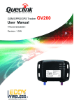
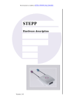
Q10 Quantum S.p.A Via L. D’Aragona, 11 - 20132 MILANO www.qtm.it Quick Guide Index Warning Page 3 Precautions and safety “ 4 Remote control “ 5 First Use “ 6 Daily Use “ 8 Audio/Video switch “ 10 Receiver Menu Settings Tv List Diagnostics “ “ “ “ 11 12 14 15 Installation “ 16 Installation and Connections “ 19 Technical features “ 20 Warning “ 21 Warranty “ 22 EQUIPMENT Each package contains: RECEIVER REMOTE CONTROL REMOTE INFRARED SENSOR POWER CAR CABLE QUICK GUIDE 2 23 ! Warranty Warranty CAUTION Dear customer, thank you for choosing our product, which has been designed and manufactured to the highest quality standards. • The product is covered by a warranty, for a period of 24 months, which is testified from a delivery document indicating the date of purchase of the product and the dealer’s name. ! This symbol means important instructions. Failure to heed them can result in serious injury or death • The customer is entitled to the rights provided for by Legislative Decree n° 24/2002 • The warranty covers the replacement or the repair operation of all the parts found to have manufacturing defects. • The warranty does not cover: › failures caused by carelessness or transport. › failures caused by installation not in accordance with the instructions › failures caused by improper, incorrect or not in accordance with the instructions, use of the device • The manufacturer cannot be held responsible for accidental damages to persons, pets, or things, as a consequence of non-conformity with all the precautions furnished with the instructions manual. › In the event you require service, during the warranty period, you should fill in and show the present certificate, together with a valid receipt issued by the dealer, showing the date of purchase of the product. WARRANTY VOUCHER DEALER’S STAMP AND SIGN Model ......................... Serial number ......................... Defect found ........................................................................... DO NOT OPERATE ANY FUNCTION THAT TAKES YOUR ATTENTION AWAY FROM SAFELY DRIVING YOUR VEHICLE Any function that requires your prolonged attention should only be performed after coming to a complete stop. Always stop your vehicle in a safe location before performing these functions. Failure to do so may result in an accident. USE THIS PRODUCT FOR MOBILE 12/24 Vcc APPLICATIONS AND NEGATIVE GROUND Any misuse that diverts from the designed application may result in fire, electric shock or other injury. Warning USE THE CORRECT AMPERE RATING WHEN REPLACING FUSES Failure to do so may result in fire or electric shock HALT USE IF A PROBLEM APPEARS Failure to do so may cause personal injury or damage to the product. DO NOT USE OLD BATTERIES When inserting batteries in the remote control, be sure to observe p r o p e r p o l a r i ty a s i n s t r u c t e d . Rupture or chemical leakage from the battery may cause malfunction ing, breakage or injury. IMPORTANT: Quantum S.p.A. declines all responsibility for any errors or omissions in this guide and reserves the right to make changes without prior notice. The information given in this guide were correct at the time of going to print. DO NOT DISASSEMBLE OR ALTER THE UNIT Doing so may result in accidents or injuries. Customer signature Date _ _ / _ _ / _ _ ............................. To return correctly filled in together with the purchase receipt 22 3 Precautions and Safety PRECAUTIONS CAUTION ! TEMPERATURE Be sure the temperature inside the vehicle is between +45°C and 0°C before turning your unit on. WATCHING TV WHILE DRIVING MAY RESULT IN SERIOUS ACCIDENTS, INJURIES OR DEATH! FUSE REPLACEMENT The replacement of the fuses must be of the same amperage. If one fuse blows more than once, carefully check all electrical connections to prevent short circuits. Also have your vehicle’ s voltage regulator checked. SAFETY MAINTENANCE If you have problems, do not attempt to repair the unit yourself. Require assistance at the nearest retailer or service station. INSTALL LOCATION Install in dry, safe locations, away from dangers and humidity. ! ! Warning Q10 complies with: E24: according to ECE R10-03 Regulation DiGiTVi: specifications D-Book ver.1.0 - June 2004 and following updates where applicable CAUTION: VIDEO OUTPUT In order to ensure vehicle safety, the driver’s side screen must be connected to the front video output connector. This will ensure the driver won’t be able to watch TV while the vehicle is moving.Iif the handbrake wire is properly connected, the driver will be able to watch TV once the handbrake is pulled. The rear passenger screens, connected to the rear video output connectors, do not fall under this restriction. Your receiver is supplied with an operating system and resident programs. While using the reciever, various softwares could be downloaded. You should not make improperly use of any of these softwares wholly or partly. Improper use means: duplication, distribution, tampering. In other words, that the only allowed usage is the one described in this user manual. INSTALLATION PRECAUTIONS Use only in cars with a 12/24 Vcc negative ground. Before connecting the device remove the negative terminal from the battery to prevent short circuits. Do not use bolts or nuts related to any safety system (airbag, etc.), To make ground connection. 4 21 i Technical features Mobile DVB-T signal reception Autotracking/Autosearch Favourite Channels List 2 video output for two separated monitor 1 audio stereo output 1 video input 1 audio stereo input Audio/video digital quality Easy and fast plug-and-play installation Remote Control DVB-T SEARCH Not in use ISO/IEC 13818-1 MPEG-2 Transport Stream ETS 300 744 DVB-T Full Compliance VHF (Band III) / UHF 21-69 DVB-T COFDM 2k/8k supported 7,8 mhZ bandwidth support Video Decoding and OSD ISO/IEC 13818-2 MPEG-2 Video MP@ML Compliance ISO/IEC 11172-2 MPEG-1 Video Compliance Resolution: 720x576 for PAL 16:9/4:3, 3:2 Letterbox and Pan/Scan 65K Colour OSD Audio Decoding ISO/IEC 13818-3 MPEG-2 Audio Compliance ISO/IEC 11172-3 MPEG-1 Audio Compliance Stereo / MTS Connections IR Remote Connector Antenna-In : Fakra type 2x Audio stereo Output (RCA L/R) 1x Composite Video Output (RCA) 2x Stereo Audio Input (RCA L/R) 1x Composite Video Input (RCA) 1x Safety and Reliability Operation temperature : -5 C ~ +55 C Storage temperature : -45 C ~ +85 C Comsuptions 0.4 A in full operation powering two antennas 0.35 A in stand by 500 microA when off (car key off) Mechanical Specification Dimensions (WxDxH): 125mm x 72mm x 35mm STAND-BY to put the unit on stand-by and to switch to a/v input SCANto start autoscan LISTto view channel list UP BUTTON to view info on program/ navigation button LIST P+/-changes channels SCAN P+ info CHANNEL P LEFT BUTTONnavigation or volume adjust button EXITto exit from the selected option BACKto return to the previous page (where available) 0…9alpha/numerical button SEARCH OK OK to select a function or to confirm the selection MENU EXIT 1 2 3 @?!. abc def 4 5 6 ghi jkl mno 7 8 9 pqrs tuv wxyz 0 MUTE BACK V+ _+ * RIGHT BUTTON navigation or volume adjust button DOWN BUTTON navigation button TV RADIO -RED, BLUE, GREEN navigation buttons -TV/RADIO - YELLOW to switch between Tv and Radio listings MUTE to switch on/off the audio input 20 5 Installation and Connections First Use Be sure that every connection has been correctly set following installation instructions at pages 16-17-18-19 SCAN TV ANTENNAS [OK] to start search - [EXIT] to quit Specifications v Getting started Q10 receiver is an automotive grade set top box able to receive free to air DVB-T Television. Turn the unit on • Please wait until frame will be shown on the screen . › press [OK] button to start the automatic channel search. To stop the search press the EXIT button. Frame will be shown on the screen. Press [OK] to confirm stop search or the [EXIT] button to resume it. SCAN [OK] to stop - [EXIT] to continue 0% At the end of the scan phase, frame will be shown on the screen. TV 12 › Press [OK] button to save the channels on the TV LIST. The first channel on the updated TV LIST will be shown on the screen. If at the end of the scan phase frame is shown on the screen, check the connections and the overall installation of the receiver, then press in sequence [EXIT], [SCAN] and [OK] buttons to restart the scan phase. RADIO 2 50% 100% TV TV TV TV RADIO RADIO v TECHNICAL FEATURES + 5V DC PHANTOM POWERED DVB-T ANTENNAS SCAN [OK] to save - [EXIT] to quit 0% TV 44 RADIO 3 50% 100% TV 1 TV 2 TV 3 TV 4 RADIO 1 RADIO 2 RADIO 3 RADIO 4 SCAN No services found - [EXIT] to quit 0% TV 0 RADIO 0 6 50% Operation frequencies: 174 - 230 (band III) 470 - 866 (bands IV - V) Gain: 18 dB Max Cable type: coaxial 75 ohm Cable lenght: 5m Connector: type FAKRA Power: +5 Vcc Consumption: 25mA min - 35 mA max Temperature range : - 40° <> +85° C Protection class: IP40 Size (L x B x H): 28 x 2,5 x 1,5 cm 100% 19 First Use Installation and Connections TV ANTENNAS TUNING Recommendations Use only active antennas amplified with adequate gain directly powered by the receiver antenna connectors and suitable to the reception of the Digital Terrestrial signal (DVB-T). Quantum Antennas, linked together with Q10 receiver, have been manufactured in order to optimize the system's functioning. These innovative automatic functions enable the receiver to still be in tune with the selected channel while on the move. Typical DTT Networks are Multi Frequency Network (MFN); each TV channel may be transmitted at different frequencies depending on the specific geographical area. WARNING: ONLY use Quantum antenna provided. Use of different antenna or external power may result in product damage and might affect the warranty terms. TV LIST CREATE SETTINGS SORT DIAGNOSTICS DEL.CHAN ADD FAVOURITE: [OK] to confirm - [EXIT] to quit DEL.LIST Once a specific TV channel has been selected, the Autotracking and Autosearch functions will tune, track and in some cases automatically search for a channel where there is a frequency change or signal loss without the need of manually starting a new search. To have the Autotracking and Autosearch functions performing in the best possible way, it is recommended to carefully follow the instructions below: v INSTALLATION GUIDELINES • Be sure to position the antennas as far away and opposing from each other as possible. For example, place the first antenna on the right side of the wind screen of the vehicle and the second one on the left side of the rear window or on the left rear vent wing. v Autotracking and Autosearch [OK] to start search - [EXIT] to quit 1.Start an autoscan - tune into the available channels in that specific area by pressing [SCAN] FAVOURITE TV TV LIST 1 Channel TV 2 Channel TV 3. Select the FAVOURITE TV LIST as default If the Autosearch function does not permit tuning into all favourite channels, start the operations described at the point 1 and 2 again but in another location. 3 Channel TV • Antennas must be installed as far away from the metal parts (vehicle's roof or vertical borders of the wind screen/rear vent wing) as possible. 2.Create a FAVOURITE TV LIST (from menu) - define and organize the list of your favourite channels 4 Channel TV 5 Channel TV 6 Channel TV 7 Channel TV [GREEN] to change list • Placing the antenna in the bonnet or the boot (depending on the vehicle) can influence the signal reception. It's recommend to experiment firstly where to place the antennas ; whether on the higher or the lower part of the window. The higher part usually guarantees more protection from noises caused by motorcycles and scooters. • Handle with care the coaxial cable setting in order to avoid damages due to vibration or crushing. • Be sure that the connections have been correctly set and check the screwing of the connectors. Signal reception's problems are often caused by incorrect assembly. 18 WARNING: channels marked in red are temporarily not available due to the lack of network coverage . FAVOURITE TV TV LIST 1 Channel TV 2 Channel TV 3 Channel TV 4 Channel TV 1 5 Channel TV 1 6 Channel TV 7 Channel TV [GREEN] to change list 7 Installation and Connections Daily Use FRONT PANEL v How to switch the receiver on Depending on the specific car installation, the receiver will be switched on as soon as the car key turns on the battery. In case an external a/v source was previously activated, please use the [ ] button on the remote control to exit stand-by mode. v How to select a channel OK MENU EXIT • USING ARROWS: select the desired channel by using the up/down buttons [5] and [6] and press [OK] to confirm the selection. IR RECEIVER 1 2 3 @?!. abc def INFORMATION BAR will be previewed on the screen before the channel tuning. V+ 4 5 6 ghi jkl mno 7 8 9 pqrs tuv wxyz AUDIO OUT R (rigth) AUDIO OUT L (left) BRAKE - Green +12/24V BATTERY - Yellow GND - Black +12/24V KEY - Red • USING PROGRAM BUTTONS: press [P+] [P-] to browse directly t h rough channels without using the [OK] button. BACK 0 _+ * MUTE AUDIO IN R (rigth) AUDIO IN L (left) TV RADIO VIDEO IN VIDEO OUT 1 (FRONT) 15 Channel TV TV 12:17 Program title 12:00 12:45 VIDEO OUT 2 (REAR) TO CAR AUDIO EXTERNAL AUDIO SOURCE SYSTEM P EXTERNAL VIDEO SOURCE • DIRECT: select the desired channel by using the numerical buttons FRONT REAR MONITOR MONITOR info CHANNEL RJ11 PORT P+ A/V ANTENNA IN 2 SCAN ANTENNA IN 1 LIST A TV or Radio channel can be selected in three different modes: WARNING: +5V PHANTOM POWER IS PRESENT TO ALL “ANTENNA IN” CONNECTORS 8 17 Installation WARNING: ! Before installing the device read carefully the following instructions HAVE THE INSTALLATION DONE BY A QUALIFIED PERSONNEL The installation and wiring of this unit require special technical skills and experiences. To ensure safety always have the installation done by experts USE SPECIFIED ACCESSORY PARTS Be sure to use only the specified accessory parts. Use of other than designed accessory parts may damage this unit or cause an incorrect functioning of the appliance ARRANGE THE WIRING CORRECTLY Route the electrical and audio/video cables and wiring away from moving parts or sharp/pointed edges. This will prevent crimping and damage to the wiring. If wiring passes through a metal hole, use a rubber grommet to prevent the wires’ insulation from being cut by the metal edge of the hole DO NOT INSTALL IN LOCATIONS WITH HIGH MOISTURE OR DUST Avoid installing the unit in locations with high incidence of moisture or dust. Moisture or dust that penetrates into this unit may result in product failure Daily Use v How to select a channel in a TV/Radio List MAKE THE CORRECT CONNECTIONS Failure to make the proper connections may result in product damage • Press [LIST] to show the TV List USE ONLY IN CARS WITH A 12 / 24 Vcc NEGATIVE GROUND Failure to do so may result in fire, electric shock or other injuries • Press [TV/RADIO] (yellow) to show the RADIO LIST LIST SCAN › Press the same button to switch between the Radio List or the previously selected TV LIST A/V • Select the desired channel BEFORE WIRING DISCONNECT THE CABLE FROM THE NEGATIVE (-) BATTERY TERMINALS Failure to do so may result in electric shock or injuries due to electrical shock P+ info CHANNEL P OK v How to adjust the volume level 1 2 3 @?!. abc def 4 5 6 ghi jkl mno 7 8 9 pqrs tuv wxyz 0 MUTE BACK DO NOT USE BOLTS OR NUTS IN THE BRAKE OR STEERING SYSTEM TO MAKE GROUND CONNECTIONS Bolts or nuts used for the brake or steering systems (or any other safety-related system), or tanks should NEVER be used for installations or ground connections WARNING: channels marked in red are temporarily not available due to lack of network coverage V+ MENU EXIT DO NOT CUT INTO ELECTRICAL CABLES Never cut away cable insulation to supply power to other equipment. Doing so will exceed the current carrying capacity of the wire and result in fire or electric shock DO NOT INSTALL IN LOCATIONS WHICH MIGHT HINDER VEHICLE OPERATION, SUCH AS THE STEERING WHEEL OR GEARSHIFT Doing so may obstruct forward vision or hamper movement etc., and result in serious accident › Press [GREEN] to switch between the general TV LIST and the FAVOURITE TV LIST if previously preset [see MENU] _+ * The volume level can be adjusted by using the [VOL+] [VOL-] buttons v Mute • Press [MUTE] to switch on/off the audio output TV RADIO v How to view program info • Press [info] to view the short information about the selected program • Press [BLUE] to get detailed informations v How to select the audio language FAVOURITE TV TV LIST To select the desired language in case of multilanguage programs follow the instructions: 1 Channel TV 2 Channel TV 3 Channel TV • Press [info] + [GREEN] and select the desired language by using the up/down[5] [6] buttons 4 Channel TV 15 16 Channel TV Channel TV 7 Channel TV v How to select the audio language [GREEN] to change list • Press [info] + [GREEN] and select desired subtitle language by using the up/down[5] [6] buttons 16 9 Audio/Video switch Menu - DIAGNOSTICS v Audio/video Inputs The receiver enables the user to connect an external audio/video source (e.g. Videogame console, DVD player, etc..) to an audio/video input (as shown on page 17) using the remote control s How to select audio/video input: Using the Power button of the remote control the user may switch from a digital TV signal to an external source signal and viceversa. WARNING: FRONT monitor should be enabled only once the handbrake control is activated. v DIAGNOSTICS Receiver provides the following diagnostics information: • SIGNAL QUALITY LIST P+ SCAN A/V • RECEIVER INFO info s How to view the DIAGNOSTICS: • Press [MENU] • Select DIAGNOSTICS by using the right and left [3] [4] buttons • Press [OK] to confirm the selection or [EXIT] to cancel it. LIST P+ SCAN A/V info CHANNEL P EXIT 10 OK V+ MENU 15 Receiver Menu Menu - TV LIST v How to manage the Favourite Tv List It is possible to create a personal favourite TV List. TV LIST and RADIO LIST include all the tuned channels which cannot be personalised. v MENU In the main MENU the sysytem’s info and user’s preferences can be seen and set. The following options are available: 1. How to create the Favourite Tv List: LIST P+ SCAN • Press [MENU] • Select TV LIST and press [OK] to confirm • Select CREATE and press [OK] to confirm • Browse the list sequentially by using the up and down buttons [5][6] , or in groups of six channels by using right and left buttons [3][4] and select the channel • Press [OK] to confirm the selection. A tick signal ü will be shown next to the selected channel • If you want to cancel the selection press [OK] again and the tick mark ü will be deleted A/V info CHANNEL P EXIT TV LIST CREATE SETTINGS SORT OK V+ MENU 2. How to delete a channel from the Favourite Tv List: • SETTINGS LIST SCAN A/V • TV LIST • DIAGNOSTICS P+ info CHANNEL P OK v How to show the Menu • Press [MENU]on the remote control V+ MENU EXIT Follow the same procedure as shown in point 1 above and replace CREATE with DELETE. DIAGNOSTICS DELETE Sub-menus: ERASE 1 Channel TV 3. How to sort the Favourite Tv List: 2 Channel TV 3 Channel TV 4 Channel TV ü 5 Channel TV ü 6 Channel TV [EXIT to quit and save TV LIST SETTINGS SORT DELETE DIAGNOSTICS ERASE ADD 1 Channel TV 01 4 2 Channel TV 02 • Press [MENU] • Select TV LIST and press [OK]to confirm • Select SORT and press [OK]to confirm • Browse the list sequentially by using the up and down buttons [5][6] or in groups of six channels by using the right and left buttons[3][4] and select the channel you want to move • Browse the list in the same way and click on the position where you want to move the selected channel. A tick mark3will be shown next to the selected channel • Press [OK] to confirm the new position of the channel SETTINGS DIAGNOSTICS TV LIST Receiver settings: [OK] to confirm - [EXIT] to quit 3 Channel TV 03 4 Channel TV 04 3 5 Channel TV 05 6 Channel TV 06 4. How to delete the Favourite Tv List: [EXIT] to quit and save Follow the same procedure as shown in point 1 above and replace CREATE with ERASE 14 11 Menu - SETTINGS SETTINGS DIAGNOSTICS Menu - SETTINGS v SETTINGS TV LIST Receiver settings: [OK] to confirm - [EXIT] to quit This sub-menu shows the data related to: • RECEIVER • RESTORE • CLOCK WARNING: In order to avoid misfunctioning of the device, BE AWARE of accidentally changing the parameters. Default settings are normally correct for standard installation. They can be restored through the RESTORE function w P+ SCAN • TV OUT Set tv out mode according your screen type: › 4:3 pan&scan › 4:3 letter box › 16:9 • MENU LANGUAGE To select the menu language • MENU COLOR To set color of menu s How to navigate the Settings Menu • Press [MENU] to view the main menu on the screen LIST w RECEIVER w RESTORE A/V • Select SETTINGS by using the right and left [3] [4] buttons. info This function enables the user to reset the input data among these data categories: CHANNEL P EXIT OK V+ • Press OK to enter this sub-menu and then press it again till you get the required item • RECEIVER DATA • Select the desired function firstly by using the right and left buttons [3] [4] and then the up and down [5] [6] buttons • CHANNELS LIST MENU • Press [OK] to confirm the selection and to move to the next function or [EXIT] to cancel the selection To reset settings, system and installation parameters To delete all the channels lists It is possible to restore data completely by selecting both items. w CLOCK SETTINGS CLOCK The receiver's clock will be automatically updated through the TV signal. If desired, one could change the time zone set at GMT+1 by default. Local time DIAGNOSTICS RECEIVER TV LIST RESTORE 11:23 Greenwich time 09:23 Offset +-01:00 [OK] to confirm - [EXIT] to quit 12 13