1
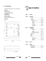
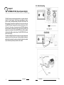
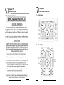
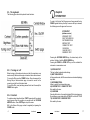
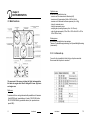
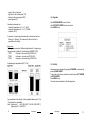
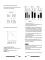
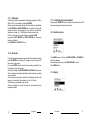
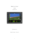
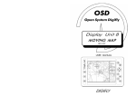
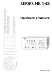
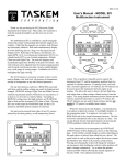
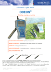
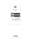
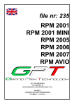
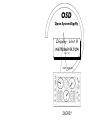
OSD
Open System Digifly
Display Unit 8
INSTRUMENTATION
SW 2.02
USER MANUAL
DIGIFLY
5.3 - Technical features.
-
20
Monochrome, high resolution, 8", 480 x 640 pixel LCD,
backlighted;
Antiscratch protection;
Contrast and brightness regolation;
Lighted keyboard;
Digifly OSD interface;
External GPS interface;
Power source: 10-28 V DC ( 0.4 Amp );
Weight 850 gr.;
Size :
User Manual
TABLE OF CONTENTS
Chapter 1
- Introduction
Chapter 2
- Getting started
- Front panel ..................................................... par. 2.1
- The display ..................................................... par. 2.2
- The keyboard .................................................. par. 2.3
- Turning On / Off ................................... par. 2.3.1
- Contrast ............................................. par. 2.3.2
- Brightness ............................................ par. 2.3.3
- Page toggle .......................................... par. 2.3.4
- Basic functions ..................................... par. 2.3.5
Chapter 3
- INSTRUMENTATION
- Main functions ................................................ par. 3.1
- Altimeters ........................................... par. 3.1.1
- Recorder .............................................. par. 3.1.2
- Switching the central window ............... par. 3.1.3
- Functions menù .............................................. par. 3.2
- Replay ............................................................ par. 3.3
- Agenda ........................................................... par. 3.4
- Set Up ............................................................ par. 3.5
- In lines set up ...................................... par. 3.5.1
- Measure units ...................................... par. 3.5.2
- Warnings ............................................. par. 3.5.3
Chapter 4
- System test
Chapter 5
- Installation
- General warnings ........................................... par.
- Electrical wiring .............................................. par.
- Technical features .......................................... par.
User Manual
5.1
5.2
5.3
1
5.2 - Electrical wiring.
chapter 1
INTRODUCTION ( Open System Digifly )
The Digifly viewing units were designed also to co-operate with each
other in the same system. This is known as “multiscreen” system
and it is made up of different Display Units (DU7-DU8) linked to the
flight recorder. Among all the connected units, only one must be set
up in MASTER mode, whereas all the others must be set up in SLAVE mode. In this manner, the viewing device (MASTER) will direct
data transmission operations and one or more devices (SLAVE) will
operate only as viewers. Only the MASTER device will be capable
of adjusting the flight-recorder settings. The MASTER/SLAVE mode
can be set in Set Up.
Therefore the Digifly Open System is now even more advanced and
complete in order to meet any need of pilots and flight enthusiasts,
significantly increasing the precision and safety standards supplied
by the instruments presently available in the market.
2
User Manual
User Manual
19
chapter 2
GETTING STARTED
chapter 5
INSTALLATION
2.1 - Front panel.
5.1 - General warnings.
2.2 - The display.
18
User Manual
User Manual
3
2.3 - The keyboard.
The following figure show the keyboard's main functions.
chapter 4
SYSTEM TEST
To enter in the System Test Page press and keep pressed the key
POWER together with any other key. As soon as the key is released,
the following menu will appear on the screen:
SYSTEM TEST
(software version)
KEYBOARD TEST
INPUT DATA DISPLAY
INSTRUMENTATION
EEPROM TEST
CONNECTOR TEST
CLEAR RAM
CHOOSE PORT 1
RESERVED TEST
Pressing the UP-DOWN ARROW keys, the desired entry will be
selected. Activate it with the RIGHT ARROW key.
Pressing the ZOOM IN o ZOOM OUT keys, will be activated the
variometer or anemometer reset.
2.3.1 - Turning on / off.
Before turning on the instrument make sure that all connections were
made correctly. Make sure the engine is turned on before the instrument.
To turn on the DUx, press the POWER button. After a few seconds, the
Moving Map or Instrumentation page is viewed to search for the
connection and for the initial internal tests.
To turn off the DUx, press (and keep pressed for at least 2 seconds) the
POWER button again.
2.3.2 - Contrast.
To regulate contrast keep the button CONTR pressed until the contrast
menu appears. Now the regulation is executed with the UP-DOWN
ARROW buttons. Press CONTR again to quit the menu.
N.B. In the System Test page, contrast is regulated just pressing the
CONTR button.
4
User Manual
1) KEYBOARD TEST
This test verifies keyboard misfunctioning.
2) INPUT DATA DISPLAY
In this operation mode, the DUx screen becomes a terminal displaying
input data.
3) INSTRUMENTATION.
Allows to qualify the intrumentation page.
4-5) EEPROM TEST - CONNECTOR TEST.
Not usable by the user.
6) CLEAR RAM
Selecting this function, it is possible to delete DUx’s internal memory.
By a submenu you can clear alle the DATABASE or all the SETTINGS
7-8) CHOOSE PORT - RESERVED TEST
Not usable by the user.
User Manual
17
2.3.3 - Brightness.
To regulate backlighting press the LIGHT button. Each time the button
is pressed, light will be increased.
3.5.2 - Measure units.
There are four presettable measure units:
Temperature (temp. unit)
: °C or °F
Altitude (unit 1)
: mt. or ft.
Speed (unit 2)
: Km/h or MPH or Knots
Pressure (unit 3)
: mb or iHg
3.5.3 - Warnings.
For each in line it is possible to fix minimum and maximum limits not
to be exceeded.
2.3.4 - Page toggle.
To toggle pages between Instrumentation and Moving Map pages, press
the MODE button in the main screen.
2.3.5 - Basic functions.
The key
- Allows to enter/exit to/from "Edit Altimeters" mode.
The key
- Allows to switch the centrale window (GPS - Sec. Instruments).
The key
- Allows to activate the recorder.
The key
- Allows to deactivate the recorder.
The keys
- Allow to ( in "Edit Altimeters" mode ) change the current Altimeter.
The key
It is possible to preset 11 engine limits (in lines from 1 to 11), and 1 flight
limit (speed) can be preset (minimum speed will be stall speed, maximum
speed will be VNE).
Limits on bar indicators are represented by little arrows on their side,
limits on round instruments are represented by a tally on the scale.
When a preset limit is exceeded the relative warning appears in the
specific window.
At the same time the bar indicator starts blinking.
- Confirm the operation on recorder ( On - Off ).
The key
- Show the main menu' in the center of the screen.
The key
- Allows to (in "Edit Altimeters" mode) clear the QFE.
16
User Manual
User Manual
5
chapter 3
INSTRUMENTATION
Flight data area
in this area it is possible to set up:
- measure unit of variometer and altimeter (mt/ft)
- measure unit of anemometer (Km/h or MPH or Knots)
- measure unit of altimeter's reference pressure (mb or iHg)
- delay of variometer arrow
- delay of anemometer arrow
- sampling rate (recording frequency from 1 to 50 secs.)
- end of scale anemometer (160 or 240 or 320 in Km/h- 80 or 160 or
240 in MPH or Knots)
3.1- Main functions.
Warnings area
In this area it is possible to set up warnings.
There are 11 presettable engine warnings, and 1 presettable flight warning
(anemometer).
3.5.1 - In lines set up.
For each in line is possible to define the type of probe connected.
None means that no probe is connected.
The upper part of the screen includes the flight instrumentation,
the lower one engine data. We will distinguish 2 areas: flight area
and engine area.
Flight area
1.anemometer.It is an analog instrument with presettable unit of measure
(Km/h)-MPH-Knots), presettable end of scale (120-240-360 Km/h or
80-120-240 MPH/Knots), presettable alarms (min. speed and max
speed-VNE-).
6
User Manual
User Manual
15
2. altimeter.
QNH
Common data area
in this area it is possible to set up:
- type of DAU10 (it can not be modified by the user)
- type of engine (ENGINE 1 - ENGINE 2 - ENGINE 3)
of this setting depends the bar graphics :
1. ENGINE 1 : 4 EGT - H20 - OIL temp. - OIL press.
2. ENGINE 2 : 2 EGT - 2 CHT
3. ENGINE 3 : 2 EGT - H20 - 1 CHT
- date and time
- mode (master/slave) (see Chapter 1)
- aircratf type (AIRPLANE - HELICOPTER - GYROCOPTER)
of this setting depends the instrument Tachometer/Rotor(7):
1.AIRPLANE: tachometer in absolute value
2.HELICOPTER: tachometer and rotor in percent value
3.GYROCOPTER: tachometer and rotor in absolute value
- outside air temperature OAT (yes/no)
- voltmeter (yes/no)
- temperature measure unit (°C or °F)
- Egt top scale (Low = 800÷1600 °F / Hi = 1200÷2000 °F)
- hourcounter (hours and minutes)
Engine data area
in this area it is possible to set up:
- number of engine poles (from 2 to 16)
- delay of RPM arrow
- step of digital indication of RPM (50/100)
- end of scale RPM (4000/8000)
- reference value (100%) for tachometer and rotor (if aircraft
type is set up as HELICOPTER)
- chanell from 1 to 11 (see par. 3.5.1 In lines Set Up)
14
User Manual
1010 mb
240 mt
QNE
1013 mb
278 mt
QNH
1010 mb
240 mt
QFE
1005 mb
216 mt
It is a digital instrument that indicates a quote related to a reference
pressure.
It is possible to switch the three altimeters (QNE-QNH-QFE) this way: by
pressing key ZOOM IN you enter the -edit altimeter- mode; now pressing
UP ARROW or DOWN ARROW you change the reference pressure
(except QNE), pressing keys LEFT ARROW or RIGHT ARROW you
modify the altitude.
If you select QFE you can zero the altitude by pressing CLEAR.
Press ZOOM IN or ZOOM OUT to exit from -edit altimeter-.
3. central window ( GPS - SECONDARY INSTRUMENTS ).
It is a window switchable by pressing ZOOM OUT.
GPS indications are:
- ADF (Automatic Direction Finder) indicator
- track (TRK)
User Manual
7
- name of the next waypoint
- flight time to the next waypoint (TTG)
- distance to the next waypoint (DST)
- ground speed (GS)
3.4 - Agenda.
Use UP-DOWN ARROW to select a letter.
Use LEFT-RIGHT ARROW to move the cursor.
Press MENU to exit.
Secondary instruments are:
- outside air temperature -in °C or °F- (OAT)
- carburettor temperature -in°C or °F- (TCARB)
- voltmeter (VOLT)
4.variometer. It is an analog instrument able to indicate values from 10mt/sec to +10mt/sec. The measure unit (mt/sec or ft/min) is
presettable in the Set Up.
Engine area
The bar graphics area has 3 different configurations for 3 engine types.
The engine type is settable by the SetUp page (ENGINE TYPE):
- TYPE 1
: 4 cylinders - liquid cooled (eg. ROTAX 912)
- TYPE 2
: 2 cylinders - air cooled (eg. ROTAX 503)
- TYPE 3
: 2 cylinders - liquid cooled (eg. ROTAX 582)
5.exhausted gas temperatures (EGT1-2-3-4).
3.5 - Set Up.
Parameters can be increased by pressing UP ARROW or decreased by
pressing DOWN ARROW.
To move the cursor from a parameter to another press LEFT ARROW
or RIGHT ARROW.
Press MENU to exit.
The main areas are indicated in the following figure.
Are represented in the left part of the bar graphics.Measure unit (°C or
°F) and alarms are presettable.
Scale: Engine type 1 - LOW (800÷1600 °F) / HIGH (1200÷2000 °F)
Engine type 2/3 - 400÷2000 °F
8
User Manual
User Manual
13
Entering this functions allows to see the latest recording.
The recorded data are those of the flight: minimum and maximum values
are displayed as shown in the drawing below.
Recorder altimetric data are represented in a graphic form :
To zoom press ZOOM IN or ZOOM OUT keys.
The ENTER key change the measure unit of the graphic from meters to
feet and viceverse.
The CLEAR key reset the graphic to maximum zoom out.
The MENU key exits.
12
User Manual
.
6. cilinders temperature (CHT 1-2-3-4).
Are represented in the right part of the bar graphics. Measure unit (°C or
°F) and alarms are presettable.Scale: 0÷700 °F.
7.tachometer (RPM).It is an analog instrument with presettable end of
scale (4000 or 8000) and presettable alarm. If the aircratf type is set
as HELICOPTER the value of this instrument is express in percent.
7b.rotor. It is an analog instrument with presettable alarm. It is displaied
if the aircraft type is set up as HELICOPTER or GYROCOPTER.
In the first case the value is express in percent, in the second case
the value is express in absolute.
8.hourcounter.It is a digital instrument presettable in the Set Up.It indicates
the working hours of the engine.
9.oil and water temperatures. It is a bar (right part) instrument with
presettable unit of measure and presettable alarms. Scale: 0÷300 °F.
10.oil pressure. It is a bar (right part) instrument with presettable minimum
and maximum limit. Scale: 0÷15 Bar.
Warning area.
11.warnings window.It is the window where appear warning messages
when one or more preset limits are exceeded.
Together with the message, the warning is indicated by the blinking of
the value out of range.
If no values are exceeded, date and present time are displayed.
Next paragraphs explain the main functions of the instrumentation page.
User Manual
9
3.1.1 - Altimeters.
This function allows the commutation of the displayed altimeter (QNE or
QNH or QFE): it is activated by pressing ZOOM IN.
When you enter this mode the window (2) of the altimeter is high lighted;
with UP ARROW and DOWN ARROW keys it is possible to change the
reference pressure (by pressing for a very short time the variation,
indicated by a beep, is a 1/10 of Millibar or relative inches of Hg).
If QFE is evidenced you zero the altitude by pressing CLEAR.
By pressing LEFT ARROW and RIGHT ARROW you change the
indication of altitude.
Press ZOOM IN or ZOOM OUT to exit.
3.1.3 - Switching the central window.
By pressing the ZOOM OUT key the central window switches from GPS
data to secondary instruments and viceversa.
3.2 - Functions menu.
3.1.2 - Recorder.
It records flight data between two time intervals.To activate the recording
press UP ARROW and a blinking “R” will appear (12) on the upper lefthand corner of the screen.
If you push ENTER within 5 seconds, the recording is activated, if not,
the recorder will not start working.
To stop the recording press DOWN ARROW and ENTER within 5 seconds.
The recording is automatically interrupted when the maximum recording
time is exceeded.
The maximum recording time is related to the Sampling rate, that is the
frequency of recording of the instrument ( from 1 to 50 secs ).
This frequency is presettable in the Set Up.
When you activate the recorder the previous recorded flight will be
completely deleted.
10
User Manual
Press MENU to enter it. Press key DOWN ARROW or UP ARROW to
select the submenu.
After selecting a submenu, press RIGHT ARROW to enter it.
Press MENU to exit.
3.3 - Replay.
User Manual
11