1
US 20060162788A1
(19) United States
(12) Patent Application Publication (10) Pub. No.: US 2006/0162788 A1
Arigoni
(43) Pub. Date:
Jul. 27, 2006
(54)
”COUNTDOWN TIMER” AUTOMATIC
(57)
WATER LIMITING SUPPLY SHUT OFF
SAFETY VALVE FLO-CONTROL SYSTEM
An electronically controlled electro-mechanical device
designed to limit a ?nite amount of Water per ?ush to a tank
reservoir of the common household toilet, or tank-less toilet
(76) Inventor: John Henry Arigoni, Clarksburg, MA
(Us)
or urinal, providing positive shuto? of Water ?oW and
anti-siphon back?oW prevention. The toilet is ?ushed, the
?ush lever activates an attached tilt sWitch, the tilt sWitch
actuates the countdown timer by means of electrical linkage,
the countdown timer in turn activates the solenoid valve by
Correspondence Address:
JOHN H. ARIGONI
924 RIVER ROAD
means of electrical connection. The Water enters the sole
CLARKSBURG, MA 01247 (US)
(21) Appl. No.:
(22)
Filed:
noid valve, passing through the valve and on to the ?oat
valve mounted to the toilet tank for ?ll up. The CountdoWn
11/303,527
timer counts doWn from the full minutes and seconds set to
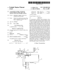
00:00 and shuts o? the solenoid valve and ultimately the
Dec. 16, 2005
?oW of Water. The CountdoWn timer then resets itself to the
time set in memory for the next ?ush operation. A ?oat
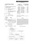
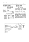
eliminator may be a?ixed to the toilet tank replacing the ?oat
valve, then connected to the solenoid valve. For the purpose
of adjusting the volume of Water per ?ush the CountdoWn
timer can be programmed from 00:00 minutes and seconds
to 99 minutes and 55 seconds. The average toilet Will need
approximately 2 minutes. It is suggested that the user ?ush
and time his toilet prior to installation of the electro
mechanical solenoid valve unit and add ?ve seconds to
Related US. Application Data
(60)
Provisional application No. 60/646,853, ?led on Jan.
25, 2005.
Publication Classi?cation
(51)
Int. Cl.
F16K 31/48
(52)
US. Cl.
ABSTRACT
(2006.01)
assure the proper volume of Water per ?ush.
...................................................... .. 137/624.11
22
32
34
10
14
16
18
12
18
16
Patent Application Publication Jul. 27, 2006 Sheet 1 0f 3
US 2006/0162788 A1
22
U
a:
J
32
34
20
H
//
14 ‘ti-1K
16
H
x M‘~4418
1s
16
FIG. 1
12
10
Patent Application Publication Jul. 27, 2006 Sheet 3 0f 3
US 2006/0162788 A1
NOTE 1: MOUNT R1 ON THESOLDER SIDE OF THE PCB
FIG 3
NOTE 2: DO NOT POPULATE R14,
NOTE 3: SOLDER A 2.2K 1/4W RESISTOR FROM ANODE OF D7 TO COLLECTORU'AB) OF T11
Jul. 27, 2006
US 2006/0162788 A1
”COUNTDOWN TIMER” AUTOMATIC WATER
LIMITING SUPPLY SHUT OFF SAFETY VALVE
FLO-CONTROL SYSTEM
[0001] I, claim priority ?ling date of Jan. 25, 2005 of
provisional Application No. 60/646,853
DISCUSSION OF PRIOR ART
[0005] Toilet systems, of the reservoir tank type generally
installed in American homes, are connected to the potable
Water supply. The average American home has at least one
of these toilets, each of Which uses approximately one and
one half to three and a half gallons, or more, of Water per
STATEMENT REGARDING FEDERALLY
SPONSORED RESEARCH OR DEVELOPMENT
[0002] Not Applicable
?ush, depending on the age of the toilet.
[0006] Generally, toilet ?ll valves are made With a ?oat
mechanism causing the valve to open When the toilet is
?ushed as the Water leaves the tank and to close once the
REFERENCE TO SEQUENCE LISTING, A
TABLE, OR A COMPUTER PROGRAM LISTING
COMPACT DISC APPENDIX
?oat is lifted by the Water When the tank or reservoir
becomes full.
[0007] Typically these toilet ?ll valves Work fairly Well
but have several draWbacks that lead to Wasting of Water,
over?ow, and leaks. These draWbacks result in a myriad of
[0003] Not Applicable
BACKGROUND FIELD OF INVENTION
Current US. Class: 4/415: 4/366; 137/436; 210/170; 713/
322
Intern’l Class: EO3D 001/00; C02F 003/02; G06F 001/04
problems from Wells running out of Water, dirt being intro
duced into the Water lines from loW Water levels in shalloW
Wells, and septic system failure, to high Water and seWage
bills for those on public Water supply and seWage systems to
Water damage to the ?oor of a bathroom, and ceilings and
Walls of a doWnstairs room to remediation of mold and
mildeW.
REFERENCES CITED
US. Patent Documents
[0008] To address these issues manufacturers and inven
tors began to develop other types of toilet ?ll valves such as
the “Toilet Tank Water FloW Shuto? Apparatus For Prevent
US. Pat. No. 6,903,766 Jun. 7, 2005 Silverbrook, et al. . . .
ing Leakage And Over?oW, US. Pat. No. 5,524,299 of
348/211.4; 348/333.06; 348/207.2; 396/264
U.S. Pat. No. 6,989,721 May 24,2005 Schmidt. . . 713/322,
713/501, 713/600; 455/205, 455/502
Dal?no, Which uses tilting trays to control Water level and
shutoff of the Water supply. Though this device can effec
tively cause shut o?“, it tends to have many external moving
4/406; 73/304c, 137/392, 137/558; 340/620
parts subject to mechanical failure and also uses most of the
toilet tank area and servicing as Well as installation require
more intensive labor and increased expense.
U.S. Pat. No. 5,752,281 May 19, 1998 Conner . . . 4/427,
[0009] A quite different approach is taken With the
4/415
Revised Automatic Water Shut O? For Stuck Open Flush
Valves In Toilet Water Tanks, US. Pat. No. 5,440,765 of
Weir, Which utiliZes a tWo cylinder system to force the ?oat
upWards to shut o? the Water supply should a continuous
U.S. Pat. No. 6,178,569 Jan. 30, 2001 Quintana . . . 4/427,
U.S. Pat. No. 5,524,299 Jun. 11, 1996 Dal?no . . . 4/415,
4/366; 137/410
137/400
?oW or Wasting of Water occur. Similar to the above is the
Toilet BoWl Automatic FloW Shut O? and Water Saver
U.S. Pat. No. 5,185,891 Feb. 16, 1993 Rise. . .4/324,4/314,
the same results With a belloWs assembly that lifts the ?oat
4/415, 33/531, 33/567
When the tank remains empty for a period of time beyond
that of normal ?ushing. Both of the foregoing devices utiliZe
U.S. Pat. No. 5,440,756 Aug. 15, 1995 Weir . . . 4/415,
US. Pat. No. 5,230,104 Jul. 27, 1993 Ocampo .
Device, US. Pat. No. 4,901,377 of Weir, that accomplishes
. . 4/415,
4/367; 4/434
a large portion of the toilet tank area to the right of the
?apper valve causing access to the ?apper to be ?anked on
all sides and tends to limit service space for repairs, causing
US. Pat. No. 5,031,254 Jul. 16, 1991 Rise. . . 4/324; 4/415
repairs to be costly and labor intensive.
U.S. Pat. No. 4,901,377 Feb. 20, 1990 Weir . . . 4/415,
[0010] Addressing the issues of conservation, the Water
Conserving Toilet Flush Control, US. Pat. No. 5,031,254 of
Rise, is a device that addresses preventing the Wasting of
Water achieved by limiting the lifting action of the ?apper
and restricting or preventing automatic operation of ?ush
137/400
U.S. Pat. No. 4,916,762 Apr. 17, 1990 ShaW . . . 4/366;
4/415; 222/16; 222/20; 251/230
[0004] “The present invention relates to the ?ll and ?ush
valves of ordinary toilets With and Without holding tanks or
reservoirs, more speci?cally to improve and expand the
scope and function of the toilet ?ll and ?ush valves address
ing the issues of Water shut o?, Water conservation, envi
ronmental preservation, Water damage prevention, anti-si
phon, back ?oW prevention, and to reduce Water production
and seWage treatment costs due to leaking toilets and
urinals.”
ing. Relatively similar in operation the Water Conserving
Toilet Flapper Valve Control, US. Pat. No. 5,185,891 of
Rise, Which in e?fect limits the height that the ?apper can be
lifted achieving the same results as the prior invention of
Rise When the ?ush lever is activated. Though both Rise
controls address stopping automatic function of the ?apper
and limiting the ?appers movement they do not address
Wasting of Water When the ?apper becomes defective by
means of bloWout, tear or just ordinary Wear of the seal, the
Jul. 27, 2006
US 2006/0162788 A1
results of Which could lead to a continuous loss of Water to
the sewer or over?ow and Water damage.
[0011] Fill valves designed to save Water such as the Toilet
Water Preservation Device US. Pat. No. 5,230,104 of
Ocampo, tend to use the ?oW of Wasting Water redirecting it
to a secondary ?oat device that in turn lifts the primary ?oat
device. This device though it appears to be quite functional
also renders much the same results as the Weir devices
mediate gear assembly then engages a spur gear seated in a
ratchet and cam assembly. The cam of the ratchet cam
assembly controls both opening and closing of a stopper.
The cam is ratcheted to the start position by a paWl con
nected to the ?ush lever of the toilet to cause the stopper to
dislodge from its seat When the toilet is ?ushed to alloW
Water to pass or ?oW, driving the Water Wheel, Which causes
the cam to turn and reseat the stopper after the desired
amount of Water has been metered through the system.
utiliZing or cluttering tank space hindering and causing labor
intensive costly service When repairing or replacing the
?apper or primary ?oat valve. The secondary ?oat ?ll valve
Although this device is impressive it has the possibility of
lockup of the drive system.
is also still subject to fail in much the same Way as the
[0016] While addressing anti-siphon ability as With the
primary ?oat ?ll valve.
other devices heretofore mentioned this particular device
also addresses back?oW prevention When the stopper is
reseated by Water pressure, but Will not stop back?oW if
Water pressure is lost during ?ll up. As previously discussed
[0012] Adaptations to ?ll valves such as the Shut-off
Device For The Float Valve Assembly Of A Toilet, US. Pat.
No. 5,752,281 of Conner, designed so that the rotation of the
lever arm causes the ?oat valve assembly to rotate to a stop
position and stop the ?oW of Water to the toilet tank in the
event that the ?oat fails to raise up for any knoWn reason
appears as an entirely different approach. While this system
would effectively shut off the ?oW of Water it is possible that
With the rotating movement of the ?oat assembly, it could
eventually cause leakage and over?oW from Wear due to
excessive movement.
[0013] Most of these devices Work fairly Well shutting off
the Water, While addressing anti-siphoning of Water but do
not adequately address back?oW prevention, Wasting of
Water if the ?oat fails to be elevated by the Water or lack
thereof, and or over?oW of the boWl or a leaky gasket
betWeen tank and toilet. Recently developed toilet ?ll valves
address one or more of these problems.
[0014]
One of the more recent toilet ?ll valves the FloW
ManagerTM AquaOne Technologies, Inc., addresses most of
these problems, incorporates the use of electronic Water
sensors that detect leaks and over?oW. The major draWbacks
of such devices are that they require regular and periodical
battery maintenance and replacement as Well as regular
cleaning of the sensor devices that appear as necessary
above, this invention utiliZes a start arm With a paWl to
ratchet forWard the cam to alloW a predetermined volume of
Water by notches ?xed in the cam. While this method
appears to be able to Work Well a shortcoming to address is
each toilet With a different tank capacity Would need a
special cam for that particular volume of Water. Additionally,
this ratchet cam system does not address the ability to adjust
the volume of Water metered so a 3.5 gallon valve Will not
service the 1.5 gallon tank of a neWer toilet or vise versa. In
other Words one siZe does not ?t all due to the arrangement
of the ?xed setting or position of notches in the cam and the
ratcheting mechanism.
[0017] Due to the fact that until the present invention no
electronic timer control for metering Water ?oW to toilets has
been developed, the search for timer modules is made in
unrelated ?elds to the effect that the Timer module for
compact printer system, US. Pat. No. 6,903,766, of Silver
brook, et al. though it is applied to printer systems this unit
can be preset to spool documents, pictures, images for
printing as Well as captures images by speci?c intervals,
hoWever it does not apply itself to the present invention’s
countdoWn timer control Where the timer control is preset to
be programmed by the user for speci?c on and off control of
clutter and are actually in the Way of cleaning the boWl and
or the ?oor. Additionally, the cleaning of the sensors and the
chemicals used, both cleansers and antibacterial toilet addi
beloW, triggered by a tilt sWitch.
tives can cause premature failure. Although the sensor in the
[0018] In addition to searching the Timer module for
compact printer systems, I felt it necessary to search at least
boWl will effectively stop over?oW of the boWl or boWl in
households With children Who might lose a toy or otherWise
plug the boWl, a ?oor sensor could present a problem With
?ushing Where bath Water is accidentally splashed on it or if
a child accidentally misses the boWl and Wets the sensor.
Electronic valve systems such as the above generally utiliZe
a normally open solenoid valve so the batteries Will last a
long time if the valve is not triggered shut by a sensor;
hoWever, if the valve is triggered shut in the case of a ?apper
leak the batteries Would not last very long Which Would in
short time lead to Water running to the seWer or Worse yet
Water damage if the boWl Was plugged.
[0015] Addressing the issues of toilet tank ?ll and ?ush
problems and Wasting of Water With control devices has
made signi?cant progress in the Positive Shut-off, Metered
Water Control System For Flush Tanks, US. Pat. No.
4,916,762, by ShaW. This device utiliZes the ?oW of Water to
turn a vaned Water Wheel. A Worm gear attached to the Water
Wheel drives a spur gear Which in turn rotates a second spur
and Worm gear. The Worm gear of the secondary or inter
electronic devices such as the solenoid valve discussed
one other timer or clock system thus for the purpose of
eliminating any infringements the Clock generation systems
and methods, US. Pat. No. 6,898,721, of Schmidt, Was
searched to compare the timer controlling processor. In the
clock generation systems and methods each of the process
ing units has a clock input to control the performance of the
unit, Wherein the processors are all receiving input from a
common master clock via a transceiver. This unit is in effect
designed to generate a clock signal to speed up performance
of computerized functions and processors and thus does not
relate to the present invention or it’s application.
SUMMARY OF THE INVENTION
[0019] Accordingly, the reader Will see in FIGS. 1 and 2
the instant invention, a countdoWn timer, and in FIGS. 1
and 4 a solenoid safety valve, comprising a safety valve
system designed to operate in conjunction With or Without a
?oat assembly by providing a limited amount of Water to any
given toilet during ?ushing su?icient to alloW a complete
Jul. 27, 2006
US 2006/0162788 A1
?ush and performing a positive shut off of the Water supply
every time a numeric display shown in FIGS. 1 and 2
other anti-over?oW devices obsolete, While preventing over
?oWs, ?ooding and excessive Waste of Water and generation
displays 00-00 even if the ?ushing operation should fail for
of unnecessary seWage.
any reason. Should a toilet ?oat, ?apper, or other tank-less
?ushing mechanism fail to operate properly and only after
the maximum amount of Water limited by time control has
passed to the tank of a toilet, a rundle of a tank-less toilet or
urinal, the electronically controlled solenoid valve of the
instant invention Will close and prevent the ?oW of Water for
the purpose of eliminating running or Wasting of Water,
preventing over?oW and or Water damage. Additionally the
valve is normally closed and doubles as a back?oW preven
tion check valve to stop any possible reverse ?oW in case of
Water pressure loss. The volume limiting shut-off action of
the present invention can be used on any common or
uncommon toilet tank of any dimension, comprising a time
programmable countdoWn timer controller shoWn in FIGS.
1 and 2, Which is turned on by means of a tilt sWitch shoWn
in FIGS. 1 and 2B, connected to said timer, by means of a
tilt sWitch transmission Wire, and a tilt sWitch plug.
[0020]
[0023] The reader Will note that there are tWo interchange
able Water delivery systems for toilets With tanks, one being
the common ?oat assembly and the other being a ?oat
eliminator. When using a common ?oat assembly the count
doWn timer and solenoid valve can be used universally
irregardless to capacity. The second delivery system is the
?oat eliminator. This system replaces the ?oat valve and
attaches to the toilet tank the same Way as the ?oat valve
assembly. HoWever this system is simply a channeling
device that directs the Water doWnWard toWards the base of
the tank for ?ll up from a delivery tube, With a replenish tube
shaft at its upper most portion for removeably connecting
the replenish tube to restore the Water level in the boWl
during ?ll up. The ?oat eliminator has been designed and
described in the present inventor’s prior invention the Toilet
King, US. patent application No. 11,090,602, and needs no
further discussion here.
A solenoid safety valve is also connected to said
timer by means of a valve poWer feed Wire depicted in
FIGS. 1 and 2B, by means of a valve poWer feed Wire plug.
The solenoid safety valve is positioned Within the Water feed
line shoWn in FIG. 1, by means of tWo compression ?ttings
to start and stop the ?oW of Water from the feed line angle
stop to the toilet during operation.
[0021] The tilt sWitch is attached to the toilet ?ush rod
shoWn in FIG. 1, by means of tWo Wire ties, When the ?ush
lever is depressed the tilt sWitch causes the countdoWn timer
to start the preset timed event Which in turn sends poWer to
the solenoid safety valve by means of the valve poWer feed
Wire and plug connection. As said valve opens the Water
?oWs from the Water feed line into the inlet of said valve
through said valve and out the outlet of said valve continuing
on into the toilet ?oat valve assembly, or through a ?oat
eliminator to ?ll the toilet tank as normal, or directly to the
rundle of a tank-less toilet or urinal.
[0022] Ideally, if used the ?oat assembly a?ixed to the
uppermost portion of the ?oat valve body Will successfully
activate shut off ?ve seconds prior to the conclusion of the
preset countdoWn timed closing of the solenoid valve
installed in the toilet Water feed line. The countdoWn timer
Will reset to its preset time and Wait for the ?ush lever to be
depressed for the next ?ush. Any toilet tank that has a lesser
volume capacity than the capacity set by time Will cause the
?oat valve to elevate and effectively shut off the ?oW of
Water and the countdoWn timer Will ?nish it’s cycle anyWay.
It is suggested for the purpose of equal control of Water ?oW
that a user should ?ush the toilet and time the ?ush prior to
installation and set the control for ?ve seconds longer than
the actual ?ush to eliminate excess over ?ush Water if the
toilet ?oat or ?apper fails. Should the ?oat or ?apper fail to
close, the tank Would call for more Water than alloWed, the
countdoWn timer Will shut off the valve and ?oW of Water
When the time limit is reached simultaneously the volume of
Water Will have been reached e?‘ectively conserving Water
and reducing the volume of seWage Waste caused by toilets
that continuously run. In effect and operation the function of
the instant invention is to shut off the Water supply after
every timed ?ush irregardless of any malfunction of the
toilet ?ushing system for any reason, ultimately rendering
all other sensor systems, gadgets, duel ?oat controls, and
OBJECTS AND ADVANTAGES
[0024] Accordingly, being designed to address the prob
lems of toilets that have been discussed With the prior art,
several objects and advantages of the present invention are:
[0025] (a) to provide a limited supply of Water by timed
volume to any given ?ush mechanism or toilet tank per
?ush irregardless of a ?apper or ?oat malfunction;
[0026] (b) to provide a failsafe positive shutoff of the
Water feed line When the maximum limit of Water by
timed volume has been reached;
[0027] (c) to prevent over?oW and limit the extent of Water
damage from a plugged toilet or seWer drain;
[0028] (d) to conserve Water, and to prevent Wasting of
Water;
[0029] (e) to reduce municipal Water production and Waste
Water treatment costs;
[0030] (f) to reduce the production of unnecessary seWage
pollution into the environment;
[0031] (g) to provide a positive means of anti-siphon and
back?oW prevention.
[0032]
Further objects and advantages are to provide a
cost-effective, easy to install toilet ?ll valve that Will not
interfere With servicing of other toilet tank parts. For
instance With the present invention should the ?apper valve
not seat properly or Worse yet rupture the Water supply Will
be shut off and the toilet tank Will be left empty and ready
for easy no muss or fuss servicing. A neW ?apper can be
installed or a leaky ?apper can be adjusted Without taking
too much time for cleanup, and once the repair is complete
all that is necessary to return to normal ?ushing operation is
to activate the ?oW of Water by depressing the ?ush lever of
the toilet tank and the tank Will ?ll up for the next ?ush. One
could even completely remove the toilet Without a Water
mishap simply by unplugging the valve 44, from the count
doWn timer 29 as the valve is normally closed.
BRIEF DESCRIPTION OF SEVERAL VIEWS OF
THE DRAWING
[0033] The present invention Will be better understood
from the folloWing detailed description as depicted in the
Jul. 27, 2006
US 2006/0162788 A1
drawings in Which like reference numerals refer to like parts;
closely related ?gures have the same number but different
handle lifts a ?ush rod 20, lifting open the ?apper by means
alphabetic su?ixes.
activates a tilt sWitch 36, connected to said ?ush rod 20 by
means of tWo Wire ties 40. Said tilt sWitch 36, is electroni
cally connected to said countdoWn timer 29, by means of a
tilt sWitch plug 35, connected to a tilt sWitch transmission
[0034] FIG. 1 is a front partial cutaWay vieW of a typical
conventional toilet tank With the tank lid removed, incor
porating the CountdoWn Timer automatic Water limiting,
of a ?apper ?ush linkage 21, simultaneously the ?ush rod 20,
present invention;
Wire 38, Which activates the countdoWn timer 29, alloWing
Water to ?oW to the tank 10, by electronically opening the
Solenoid Safety Valve 44, for a time period set by the user
[0035]
su?icient to alloW for a complete ?ush.
supply Shut olf Safety Valve ?o-control system of the
FIG. 2 is a front vieW of the CountdoWn Timer of
the present invention;
[0036]
FIG. 2A is a rear vieW of the CountdoWn Timer of
[0045]
As shoWn in FIG. 1, the countdoWn timer has three
the present invention;
buttons; the ?rst is a set button 46, the second is a minute
button 48, and the third is a second button 50. Although self
[0037]
explanatory the operation and function Will be discussed a
FIG. 2B is a side vieW of the CountdoWn Timer of
the present invention;
little later on.
[0038]
[0046] Also shoWn in FIG. 1 the reader Will note there is
a poWer indicator LED 52, a charge indicator LED 54, and
FIG. 3 is the CountdoWn Timer schematic of the
present invention;
[0039] FIG. 4 is a cutaWay front vieW of the supply shut
off solenoid valve of the present invention;
DETAILED DESCRIPTION OF THE
INVENTION
a loW battery LED 56, though easily understood, the purpose
and function Will be discussed a little later on.
[0047] AWall transformer 32, Which is plugged into a Wall
outlet 22, is connected to the countdoWn timer 29, by means
of a Wall transformer poWer cord 34, a Wall transformer plug
33, and a Wall transformer plug receiver 31, mounted solidly
[0040] The folloWing description is provided to enable any
to a enclosure side 25 as depicted in FIG. 2B.
person skilled in the art to make and use the invention and
those so skilled to do so.
[0048] FIG. 2 is a front vieW of the countdoWn timer 29,
as described in FIG. 1. The preferred embodiment of said
[0041]
countdoWn timer 29, is comprised of an enclosure front 24,
consisting of tWo equal siZed numeric displays 30, to alloW
sets forth the best modes contemplated by the inventor for
FIG. 1 is a front vieW of a conventional toilet tank
10, of the type universally found in most homes in the
the user to program and vieW the run time and see the
United States and North America, Which is ?tted With a
running countdoWn When activated. The countdoWn timer
29, is turned on and programmed by means of three control
CountdoWn Timer 29, and a Solenoid Safety Valve 44, in
accordance With the present invention. In the conventional
home toilet, a ball cock assembly comprising a ?oat arm,
and ?oat ball is mounted at the upper end of a Water tube for
closing an inlet valve via a mechanical linkage When the
tank is ?lled to a predetermined level. In the present inven
buttons. The control buttons consist of a set button 46,
colored red, a minute button 48, colored green, and a second
button 50, colored yelloW, located beloW and slightly to the
[0042] The illustrated toilet tank comprises a toilet tank 10
With a ?oat valve inlet 14, extending through the left rear
bottom of the tank 10. Water supply is introduced by means
of a Water feed line 16, Which is connected by knoWn means
of a standard siZed ?tting as currently used With ?ush tanks,
providing a sealable mount to the tank 10. A Solenoid Safety
Valve 44, is ?tted into the Water feed line 16, by means of
left of the numeric digital display 30. To turn on the
countdoWn timer 29, the operator or user Will depress and
hold the second button 50, then depress the set button 46. To
set the running time for countdoWn the user Will press the set
button 46, until the numeric displays 30, ?ash 00 and 00. The
user Will then set the minute run time by depressing the
minute button 48, once for each minute desired and then
depress the second button 50, once for every ?ve (5) seconds
desired. Once the time has been selected the user Will then
depress the set button 46, to commit the run time desired to
memory.
tWo compression ?ttings 18. Water received in tank 10,
Which exceeds the tank’s design capacity spills into a
standard over?oW tube Wherefrom it is discharged to the
boWl through the main tank outlet 12, Which is normally
closed by a standard ?apper. When Water from tank outlet
user Will ?nd three indicator LEDs, the uppermost being a
poWer indicator LED 52, colored red When lit to indicate that
a Wall transformer 32, is connected to the countdoWn timer
29. The middle being a charge indicator LED 54, colored
tion a ?oat valve assembly is left unchanged being mounted
to the tank in its usual fashion.
12, is introduced into toilet boWl the level of Water in boWl
is raised until it exceeds the Waste outlet of the ?ush trap
causing the Water to ?oW from boWl by siphoning action.
[0043] As demonstrated in FIG. 1 and again in FIG. 2B,
the solenoid safety valve 44, is electronically connected to
[0049] To the right and beloW the numeric displays 30, the
green When lit to alloW the user to see When the countdoWn
timer 29, is in charge mode. The loWer most being a loW
battery indicator LED 56, colored yelloW to alloW the user
to see the condition of the battery.
44, during operation.
[0050] FIG. 2A is a rear vieW of the enclosure back 26, of
the same dimensions and mating the enclosure front 24,
consisting of tWo enclosure screWs 27, located center from
side to side and in from top and bottom edges su?icient to
[0044]
hold said enclosure front and back securely together While
the countdoWn timer 29, by means of a valve poWer feed
plug 41, and a valve poWer feed Wire 42, to open the valve
FIG. 1 shoWs, a ?ush handle 19, located in the
upper left front area of the tank 10, used to activate the
accommodating the electronics Within, and keeping in place
?ushing operation of the toilet. When depressed the ?ush
tWo enclosure sides 25, of the same dimensions. One side
Jul. 27, 2006
US 2006/0162788 A1
being without plug receivers, the other side being with plug
receivers as depicted in FIG. 2B.
Table of Contents
[0056] 1. Power Supply, Voltage Regulator, Battery
Charger
[0051] As depicted in FIG. 2A in the rear view of the
enclosure back 26, the reader will ?nd a wall hanger hole 28,
for mounting to a wall with a wall anchor screw (not shown).
[0057] 2. Micro-controller
[0052]
[0058] 3. The Displays
FIG. 2B is a side view of the countdown timer 29,
depicting the enclosure side 25, with left and right sides
being of the same dimension. The difference between the
two sides is that the right enclosure side 25, is ?tted with a
tilt switch plug receiver 39, a wall transformer plug receiver
31, and a valve power feed plug receiver 43.
[0053] FIG. 3 is the Countdown Timer schematic of the
present invention as described hereafter by: Naveen
Negasha, TronicsZone as per consultant’s contract for hire.
[0054] Countdown Timer Parts List below itemiZes the
existing electronic components used as depicted in FIG. 3
showing the Countdown Timer schematic of the present
invention.
[0059]
4. The O/P Load Driver
[0060]
5. The User Interface
[0061]
1. Power Supply:
[0062] Voltage Regulator:
[0063]
The circuit works at a regulated 3.3 v DC. A
voltage regulator LP 2950 is used for the purpose of regu
lating the 9 v DC input. Abattery backup is also provided for
smooth operation of the Timer. The Regulator is supplied
with, both the voltages, from battery (6 v) and the external
power source (9 v). These are fed to the regulator through
Countdown Timer Parts List
Qty Part Name
Value
PBC Marking
3
Switch, tact, 4 pin, (12 mm)
MINUTES, SECONDS, SETiTIME
1
Switch, tact, 2 pin
RESET
2
Connector, Power, coaxial 2.1 mm
11, I2
1
1
6
2
Solder points
Connector, relirnate, 6 pin
Capacitor, SMD, 0603
Resister, SMD, 0603
BAT
PROG
0.1 uf
1k
c1, c4, c5, C6, c9, 010
1
Diode
1N4007
D5
3
4
1
1
1
3
2
1
2
Diode
Resister, SMD, 0603
Resister, SMD, 0603
Crystal, HC49
Resistor, CFR, 2 W
Resistor, SMD, 0603
Capacitor, SMD, 0603
Resistor, SMD, 0603
Resistor, SMD, 0603
1N5819
2K2
3K3
4 MHZ
SE6 (2 W)
10K
22 pF
39K
100K
D1, D3, D4
R10, R16, R20, R24
R2
Q2
R1
R5, R12, R23
C7, C8
R8
R6, R7
1
1
1
9
Capacitor, polarized
Capacitor, polarized
Resister, SMD, 0603
Resistor, SMD, 0603
100 uF/16 v
100 uF/25 v
220K
330E
C3
C2
R4
R3, R11
R9, R13, R14, R15, R17,
R18, R19, R21, R22
1
1
IC
LED, Yellow, 3 min
ATMEGA48V-10AI IC2
BAT LOW
D8
1
4
Transister, SMD, SOT23
Transister, SMD, SOT23
BC848
BC858
T2
T3, T4, T5, T6
1
1
1
4
1
Diode, Zener
LED, Green, 3 mm
Transister, SMD, SOT223
Display, Common anode
MOSFET, DUAL
C3V3PH
CHARGING
FZT788B
KLS351-CA
IRF7307
D2
D7
T1
1
IC
LP2950
IC1
1
1
Connector, Stereo socket
LED, Red
PG203J
SUPPLY IN
X1
D6
CNT-DN-TMR-1.0
1
PCB
1
Battery
6 V, 1.3 Ah
1
Output Cable
i
1
Tilt switch cable assembly
i
D1s1, D1s2, DIS3, DIS4
Q1
[0055] Count Down TimeriHardware Description
Document Version Date Description
two Diodes (D1 and D2). D1 will avoid the external power
source from loading the Battery, and the D2 will avoid the
high voltage input directly fed to the Battery. The ?lter
v1.0 25 Aug. 2005 First release of this document By Naveen
capacitors C1-C4 are provided at the input and the output of
Negasha, TronicsZone as per contract for hire.
the Regulator.
Jul. 27, 2006
US 2006/0162788 A1
[0064] Battery Charger:
[0071] 3. The Displays:
[0065] The Voltage across the battery is continuously
monitored by the Micro controller for OVer/Under Voltage
protection to the Battery. If the same is found dropped
type 7-Segment Displays, to display the Minutes and Sec
onds. These are multiplexed by four PNP Transistors (T3
belloW the pre-set threshold of 5.75 V, the “BAT LOW”
(YELLOW) LED Will be ON. The Charger Will be on
WheneVer the Battery Voltage reaches 5.2 V, and as an
indication the “CHARGING” (GREEN) LED Will be ON.
The Charger consists of tWo transistors T2 and T3. The
Charger Control from the Micro Controller Will go high as
soon as the Voltage across the battery drops to 5.2 V. This
Will put the T1 in ON state, noW the R3 (1 K) and the Zener
Diode D3 (2.7 V) together Will proVide a constant Voltage at
the base of T1. The T1, While it is ON, Will proVide the
battery With a constant current (Ich) Which can be calculated
as per the folloWing Equation.
[0066] Ich: The Battery charging current
[0067]
V2: The Voltage across the Zener Diode
[0068]
Re: The resistance connected at the Emitter of T1
[0069] The CHARGING LED is connected to the collec
tor of the T1; so that When eVer the Charger is ON and the
external poWer source is connected the LED Will indicate the
charging.
[0070]
[0072]
The Count doWn timer has four common Anode
T6). The seVen segments are connected to the Micro Con
troller through current limiting resistors.
[0073] 4. The O/P Load DriVer
[0074] The system can drive a load With the rating of 6 V/2
A during the Count DoWn. The OUTPUT Will be supplied
from the battery. A fully charged (6.9 V) battery Will serVe
the Load nearly 20 to 30 Minutes @ 6.0 V/2 A. The Load is
sWitched On/OFF through an N-Channel FET (Q1) Which
has a current rating up to 3 A. The resistor R7 Will alWays
keep the Gate at the GND potential, so that the load is
disconnected as long as the output from the controller is
LOW. As soon as the Gate goes high the FWT Will be put
ON, and the Load Will be serVed With the 6 V from the
Battery. The Load Will be ON during the Count DoWn, and
Will be put OFF When the Count reaches “00 00”. During the
Count DoWn the Battery Charger Will be put OFF.
[0075] 5. The User Interface
[0076] The “Count DoWn Timer” has been proVided With
three (3) “Push to On” type sWitches, Which are labeled as
“SET TIME”, “MINUTES”, and “SECONDS”. Three
LEDs, Which are labeled as “POWER”, “CHARGING” and
“BAT LOW” are also proVided for indicating the Various
PoWer statuses. The User Manual can be referred for more
2. Microcontroller: An Atmel AVR series micro
details. The user interface is entirely controlled by the
controller “ATMEGA48” is used as a processor in this
microcontroller.
project. The microcontroller forms the brain of the circuit
and it controls all the functions of the Count doWn timer
[0077] The folloWing CountdoWn Timer FloW Chart
beloW submitted By NaVeen Negasha, TronicsZone, as per
contract for hire. With the schematic and components parts
including battery charging, count doWn, sensing tilt sWitch,
setting the timer, controlling the load, controlling the LEDs
etc.
list shoWs the How of current and function of components as
described aboVe.
US 2006/0162788 A1
Jul. 27, 2006
COUNT DOWN TIMER - FLW CHART
C ST‘RT )
‘SET mAE'KEV YES
swans
YES sum KEY‘
ANY
KEY PRESS ‘I
V>BAT LOW
V<BATLOW
GET BATTERY
VOLTAGE V‘
m
m:
‘START KEY
'SEI'TIE‘ KEY
'
LOAD 0N
‘IIINUTES' KEY
“We FOR
sscouos- KEY
KEY PRESS
‘
mm In: 0 1
5500040
INCREMENT
MmuT£ BY '1'
“CREME”
SECOND BY .5.
no
n: is
mun-7
YES
m
LOAD OFF
‘SETTHE‘ KEY
‘
ENABLE
'srrmr KEY
D
;
an LOWLED ou
BATLOWLEDOFF
YES
v <BATBAD
7
"°
c
camcm
IS on ?
N0
ves
was on
am'razvcmnczn
Jul. 27, 2006
US 2006/0162788 A1
[0078] The Countdown Timer, microprocessor’s program
mable memory is factory programmed by means of com
puter interface, wherein the programming ?les on the
accompanying CD labeled “Countdown Timer Program
ming and Instuctions” Copy 1, are down loaded to the
is opened and closed by means of a valve shaft 76, to which
it is permanently af?xed. Said valve shaft 76, is made of
material suitable to magnetic pull. Said valve shaft 76,
moves towards a valve shaft end plug 84, made of suitable
magnetiZable material by means of an electromagnetic ?eld
memory of the countdown timer, from a IBM-PC with a
generated within a valve shaft chamber 82, being forced
MS-Windows NT/2000/XP operating system, consisting of
the following ?les;
[0079] Disk labeled: Countdown Timer Programming and
Instructions Copy 1, written
closed by means of a valve shaft spring 80, when there is no
power to created said electromagnetic ?eld. Said valve shaft
76, is able to move into the open position easily without
resistance due to back pressure reduction by means of a
valve shaft ?ute 78, which allows the water at said plug end
84, to move freely towards said valve seal end 72. Said valve
shaft chamber 82, is surrounded by a valve shaft chamber
[0080]
To disk on Dec. 15, 2005. Copy 2, written To disk
on Dec. 15, 2005.
Date Modi?ed: Type of ?le:
File size:
Date loaded to disk:
Files on disk:
Cntdwntimr
CntDwnTimr
CntDwnTimr
cntdwntimr.c~
CntDwnTimr.eep
Cntdwntimr
CntDwnTimr
CntDwnTimr.cof
CntDwnTimr
CntDwnTimr
cntdwntimr.h~
CntDwnTimr.hex
CntDwnTimr.ls~
CntDwnTimr.lst
CntDwnTimr.map
CntDwnTimr.pr~
CntDwnTimrprj
CntDwnTimr.rom
CntDwnTimr.vec
CntDwnTimri
CntDwnTimricof
swart
swart
swart
Jul. 01, 2005
Jun. 30, 2005
Jun. 30, 2005
Jun. 30, 2005
Jun. 30, 2005
Jun. 30, 2005
Jun. 30, 2005
Jun. 30, 2005
Jun. 30, 2005
Jun. 30, 2005
Jun. 30, 2005
Jun. 30, 2005
Jun. 13, 2005
Jun. 30, 2005
Jun. 30, 2005
Jun. 27, 2005
Jun. 30, 2005
Jun. 30, 2005
Jun. 30, 2005
Jun. 30, 2005
Jun. 7, 2005
Jun. 6, 2005
Jun. 8, 2005
Jun. 8, 2005
C File
ASM File
INC File
C~File
EEP File
H File
Error Log
COF File
OJB File
Text Document
H~File
HEX File
LS~File
LST File
MAP File
PR~File
PR] File
ROM File
VEC File
C File
APS File
C File
H File
H~File
16.5
50
1
17
1
4
1
7
8
5
4
5
75
80
2
4
4
11
1
17
3
2
1
1
KB
KB
KB
KB
KB
KB
KB
KB
KB
KB
KB
KB
KB
KB
KB
KB
KB
KB
KB
KB
KB
KB
KB
KB
Dec.
Dec.
Dec.
Dec.
Dec.
Dec.
Dec.
Dec.
Dec.
Dec.
Dec.
Dec.
Dec.
Dec.
Dec.
Dec.
Dec.
Dec.
Dec.
Dec.
Dec.
Dec.
Dec.
Dec.
15,
15,
15,
15,
15,
15,
15,
15,
15,
15,
15,
15,
15,
15,
15,
15,
15,
15,
15,
15,
15,
15,
15,
15,
2005
2005
2005
2005
2005
2005
2005
2005
2005
2005
2005
2005
2005
2005
2005
2005
2005
2005
2005
2005
2005
2005
2005
2005
Jun. 30, 2005
Jun. 20, 2005
Dec. 9, 2005
Jun. 18, 2005
Jun. 18, 2005
Wordpad Document
File
File
EEP File
HEX File
119
33
4
1
5
KB
KB
KB
KB
KB
Dec.
Dec.
Dec.
Dec.
Dec.
15,
15,
15,
15,
15,
2005
2005
2005
2005
2005
Apr. 4, 1996
Sep. 27, 2003
May 14, 1999
System File
MSiDOS Batch
Application
MSiDOS Batch
Application
Text Document
Text Document
MSiDOS Batch
MSiDOS Batch
6 KB
1 KB
157 KB
Dec.
Dec.
Dec.
Dec.
Dec.
Dec.
Dec.
Dec.
Dec.
15,
15,
15,
15,
15,
15,
15,
15,
15,
2005
2005
2005
2005
2005
2005
2005
2005
2005
Firmware loading
instructions
isp12dev
isp12rc
decodereep
decoderhex
giveio
install
instdrv
lock
spl2
spl2
spl2dev
uninstall
upload
[0081]
Jun. 24, 2005
Feb. 17, 2003
Feb. 7, 2003
Jan. 28, 2003
Sep. 27, 2003
Jun. 30, 2005
File
File
File
File
1 KB
58
48
9
1
1
KB
KB
KB
KB
KB
FIG. 4 is a cutaway view of the solenoid safety
valve 44, comprised of a valve body 60, consisting of an
inlet chamber 64, and an outlet 66, externally or internally
threaded to accept NPT 62, of a siZe necessary to connect to
the water feed line of the toilet used. A ?ow port 68, of
sufficient diameter allows the water ?ow between the inlet
chamber 64, and the outlet chamber 66. At the outlet
chamber end of the ?ow port 68, is a valve seat 70. A valve
seal 72, stops the ?ow of water through said ?ow port 68,
when in contact with said valve seat 70. The valve seal 72,
wall 88, and is molded to a valve shaft chamber base 86.
Said chamber base 86, is mounted to said valve body 60, by
means of four chamber base mounting screws 90, and sealed
by means of an o-ring 74, of suitable material. An electro
magnetic ?eld is generated by means of a solenoid coil wire
94, of suitable gauge and length to create said ?eld by means
of winding said wire around a solenoid coil spool 92, and
placing said coil spool 92 over the valve shaft chamber wall
88. To charge said coil 94, electric current of the proper
voltage must be introduced by means of a positive lead wire
Jul. 27, 2006
US 2006/0162788 A1
96, and a negative lead Wire 98. Said solenoid coil Wire 94,
is covered by means of a solenoid coil casing 100, held in
place by means of a solenoid casing screW 102. Said positive
2. The CountdoWn Timer, automatic Water limiting, sup
ply shut o?‘, safety valve ?o-control system of claim 1
lead Wire 96, and negative lead Wire 98, pass through said
Wherein certain external enclosure components of said sys
tem and are composed of suitable plastic materials of the
solenoid coil casing for access to electrical current to create
manufacturers choice;
the electromagnetic ?eld needed to open said valve seat 72.
[0082]
Those skilled in the art Will appreciate that various
adaptations and modi?cations of the just-described preferred
embodiments Which can be con?gured Without departing
from the scope and spirit of the invention. Therefore, it is to
be understood that, Within the scope of the appended claims,
the invention may be practiced other than as speci?cally
described herein, such as use of a larger volume solenoid
safety valve 44, on a tank-less toilet or urinal and using a
push button to start the countdoWn in place of a tilt sWitch
36, to activate the ?ush cycle, or With any other electroni
cally controllable device.
3. The CountdoWn Timer, automatic Water limiting, sup
ply shut o?‘, safety valve ?o-control system of claim 1
Wherein certain internal components of said system are
composed of suitable electronic parts and materials of the
manufacturers choice;
4. The CountdoWn Timer, automatic Water limiting, sup
ply shut o?‘, safety valve ?o-control system of claim 1
Wherein said microprocessor memory means is comprised of
suitable capacity of the manufacturers choice;
5. The CountdoWn Timer, automatic Water limiting, sup
ply shut o?‘, safety valve ?o control system of claim 1
Wherein said programmable memory is factory programmed
by means of computer interface, Wherein the programming
What I claim to be secured by Letters Patent of the United
States is:
?les on the accompanying CD “CountdoWn Timer Program
ming and Instructions” Copy 1, are doWn loaded to the
1. A CountdoWn Timer, automatic Water limiting, supply
shut off, safety valve ?o-control system for use With toilets
With or Without tanks and urinals comprising:
memory of the countdoWn timer, from a IBM-PC With a
a countdoWn timer enclosure;
MS-WindoWs NT/2000/XP operating system;
6. The CountdoWn Timer, automatic Water limiting, sup
ply shut o?‘, safety valve ?o-control system of claim 1
a means for housing a circuit board Within said enclosure;
Wherein said user end memory is programmed by means of
three (3) “Push to On” type sWitches, Which are labeled as
a means for attaching electronic components to said
circuit board inclusive a microprocessor memory com
“SET TIME”, “MINUTES”, and “SECONDS”.
7. The CountdoWn Timer, automatic Water limiting, sup
ponent;
a means for programming said microprocessor memory
component;
a means for housing a battery Within said enclosure;
a means for charging said battery;
a means for regulating charging voltage and operating
voltage;
a means to indicate poWer on, charge on, and loW battery
status;
a means of programming run time for said countdoWn
timer;
a means of displaying programming and run time set for
said countdoWn timer;
a means for starting said countdoWn timer;
a means for attaching said starting means to a toilet ?ush
control lever;
a means for connecting said countdoWn timer output
poWer to an electrically controllable safety valve ?o
control (solenoid valve) for shutting off or permitting
Water How;
an inlet means for connecting said electrically control
lable safety valve ?o-control to the Water feed line of a
toilet or urinal providing a connection to a source of
Water under pressure;
an outlet means for connecting said electrically control
lable safety valve ?o-control to the inlet of a toilet or
urinal;
a normal closed valve position means for preventing
back?oW Within said inlet means;
ply shut off, safety valve ?o-control system of claim 1
Wherein said programming display means has four common
Anode type 7-Segment Displays, to display the Minutes and
Seconds, multiplexed by four Transistors. The seven seg
ments are connected to the Micro Controller by means of
current limiting resistors, comprised of suitable resistance of
the manufacturers choice;
8. The CountdoWn Timer, automatic Water limiting, sup
ply shut o?‘, safety valve ?o-control system of claim 1
Wherein said memory means is comprised of suitable capac
ity of the manufacturers choice;
9. The CountdoWn Timer, automatic Water limiting, sup
ply shut o?‘, safety valve ?o-control system of claim 1
Wherein said battery means is comprised of suitable voltage
of the manufacturers choice;
10. The CountdoWn Timer, automatic Water limiting,
supply shut o?‘, safety valve ?o-control system of claim 1
Wherein said charging means is a voltage regulator of
suitable voltage to charge said battery;
11. The CountdoWn Timer, automatic Water limiting,
supply shut o?‘, safety valve ?o-control system of claim 1
Wherein said charging is monitored by means of a poWer
LED indicator, a charge LED indicator and a loW battery
LED indicator of the manufacturers choice;
12. The CountdoWn Timer, automatic Water limiting,
supply shut o?‘, safety valve ?o-control system of claim 1
Wherein said start means is comprised of a suitable elec
tronic sWitch of the manufacturers choice;
13. The CountdoWn Timer, automatic Water limiting,
supply shut o?‘, safety valve ?o-control system of claim 1
Wherein said safety valve and certain external components
are composed of suitable non-corrosive materials of the
manufacturers choice;
14. The CountdoWn Timer, automatic Water limiting,
supply shut o?‘, safety valve ?o-control system of claim 1
Wherein said safety valve and certain internal components
US 2006/0162788 A1
Jul. 27, 2006
10
are composed of suitable non-corrosive magnetically moveable materials of the manufacturers choice;
15. The Countdown Timer, automatic Water limiting,
supply shut off, safety valve ?o-control system of claim 1
Wherein certain internal components of said safety valve are
composed of suitable electrical materials of the manufac
turers choice;
16. The CountdoWn Timer, automatic Water limiting,
Whereby, said Countdown Timer, automatic Water limit
ing, supply shut off, safety valve ?o-control system Will
activate by means of a tilt sWitch causing a preset
countdoWn to open and hold open said safety valve for
a pre-determined programmed length of time thereby
alloWing How of Water to facilitate the ?ushing cycle of
a toilet, and closing said safety valve When said count
supply shut off, safety valve ?o-control system of claim 1
Wherein said safety valve is connectively threaded at its
upper most outlet by means of a outlet compression ?tting
doWn reaches 00 00 thereby limiting a certain amount
of Water by volume to pass to the toilet and providing
positive shutoff of the Water, after Which said count
doWn timer Will reset for the next ?ush cycle. When
closed said CountdoWn Timer, automatic Water limit
to a outlet chamber means for mounting said control to the
?ush tank of a toilet tank or tank-less toilet or urinal;
doubles as a back How prevention device. The Count
17. The CountdoWn Timer, automatic Water limiting,
supply shut off, safety valve ?o-control system of claim 1
Wherein said safety valve also referred to as a solenoid valve
is connectively threaded at its loWer most inlet by means of
a inlet compression ?tting to a inlet chamber means for
providing a connection to a source of Water under pressure;
ing, supply shut off, safety valve ?o-control system
doWn Timer, automatic Water limiting, supply shut off,
safety valve ?o-control system Will limit a certain
amount of Water by volume per ?ush, prevent Wasting
of Water, over?oW, anti-siphoning and back?oW of
Water from a toilet.
*
*
*
*
*