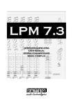
1
Navigator
User's Manual
WIRELESS2,5" COLOR
SYSTEM
TFT LGDMONITORING
- Portable2.5" Color TFT LCD with Receiver
- WirelessColor Camera
PLEASEREADCAREFULLY
AND SAVE
This manualcontainsimporiantinformation
aboutthisproduct'soperation.
lf you are installing
thisproductfor useby othersyou mustleavethis
manual-or a copv-withthe end user.
@ffiHMEffi
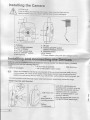
I nsta l l i n gthe Cam er a
ATTENTIONi
Prlorlo dr,,l:ngari.nsaittr:E:hescie..!srra<e
sLreIhalth.,.eare no
erectnccabteso,oesetc.|n ihe walllhatmay becone
damaged.
^-^--^
.X / c.\
Yo
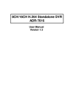
2 Low battery indicator
3 Power indicator
4 Eye ball camera lens
5 Power ON/OFFswitch
6 Microphone
7 IR LED
8 Camera ON/OFF switch
(camera Kitbaby monitof)
I Channelswitch
10 OC Power
11 Poweradaptorplug with low voltageswttch
Installing and Connectingthe Devic.es
Selecl a suitabie installationsile from whichyou
want to monitorthe desiredobject.A suitable
installalionsite has the followingteatures:
dry
as dust-freeas possible
. litflevibralions
goodair circulation
with a wall ou|et in closevicinjty
seleclan installaiion
sitethat's notscfeenedoff by
concrete
wa s, minors,
metalshetves,etc.ctoselo thesenderrespeai"ai reinforced
,"""""iG"i" .tiitj-no, o"
apprrances
wth sirongelecricfieids,e.g.ce pt *'"", vl"rti""r"riL",Ji"lrii"
"ny
"ngin"., "t".
Theabovepoinlscouldseverelyimpairradiotransmission
aespeciively
reducetherange.
Fasteningthe wall bracket
[€
wattmountslol
attachslandto
mounting
surface
battery
compartment
Look ior a suitableplacefor
mounting(witha socket close_bv)
Screwthe wall bfacketwith the
suppliedscrewsto a sujtable
lvall of a suilableplatform,use
dowelsif relevant.
Alignthe camefaand screw lhe
corrugatedplasticsleevetight.
t
I
Connectingthe camera
Conne.che smallvoltageplugof the power_unll
to the vollagesupplylack of lhe ca, era.
Pay al'enr,on'olhe correcroLlprrlvoj.ageof 7.5V
DC,
. rnsei tfe plLg.inpowerun.r;nto
a s.titaolenarn socket.
. The camerais novr'readyior
use,
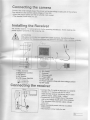
Installingthe Receiver
.l
approx m aboveground(betterfeceivingconditions).
l:o ToniJgr
There must be ofe
power
oLltletin proxtrniiylo the receivjngstte.
ATTENTIONi
tl"
on ruggedandstabjesurfaces.
Sensitive
?-"]I
ll"-". lhal
I3"(g,
suriac:s
of
surtaces
dissolve
sofienefs
ma),/
become
damageC.
Usaa s!iiaai:i_a::,:."
.-----:
* 1 ? ?.
'--Ei_,
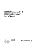
1 VOL.Control
2 BrightnessControl
3 CH Select
4 AN Output
5 LCD PowerON/OFF
aF ParGR
cN
!L ar"rElqbir
5 DC Power
7 Antenna
I ChannetLED
9 PowerLED
1OBAT,LOWLED
]1ffi;;X"*"'
ntrswithtowvottase
slvitch
Connectingthe receiver
. Connecllne AV
cableas oepicredto a sutraDle
monttoror TV systernwithan AV cjnch
,nputand the receiverfwhile/reoptuq =
auC,o
(lonein mono),yellowpluq=
. Lonnectlhe smal'voltage vrdeot.plLgot the po,ver
unrrlo lne vollagesupplyjackofthe
recelvef.
r€yvallentionio lhe correcloutpul
vol3ge
. Insertthe plug-inpowef
unit jnto a sujlabte
matnsocket
- The feceiveris
now readyfor use.
ir.
Systemlnstallation
when installingthe camera,check the receptionof the monitorbefofe flnai installation.Have someone
hold the camerain lhe afea lo be monitored.Have anotherpersonmove ihe monitorto a varietyof
Iocalionsihroughoutlhe houseto check reception.lf interferenceor other problemsoccur,referto the
T.oubleshootingGuide.
Wireless 2.5" Color TFT LCD Monitoring Sysetem
To install the system, follow these step!:
Monitor:
1. Plug the 5V AC/DC adaptercord into the DC Input Jack on the side of the monitor.
2. Plug the adapterinto a standard(1.10V-240V)
AC ouflet.press ihe powerbuttonio iurn on the
monltot.
3. ,4^/ oulputs on the LCD monitorcan be connectedto the A / input on a TV set for a lafge screen
display,or to the FJV inputson a VCR for recofdinq.
4 You can use eitherAC/DC adapterfof long time u; of 4 "A,qA' batteryfof mobiteuse.
The life time oJ4 "AArq"bahery operationis 45 minutes.
Gamera:
1. Plug the 7.5V AC/DC adaptercord into the DC inDutiack on the back ofthe came|a.
2. Plug the adapterinto a standard(.1.10V_240V)
AC ouitet.
3. You ca_nuse eitherAC/DC adapterfor long tjme use or 2 "AA" batteryfor mobileuse.
The l;fe time of 2 "AA" batteryoperationis .l.ShrWo lR tunctionand thr W lR funclon.
System Setup:
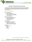
1 Selectlhe channel(Channel1-3) to be used on both lhe cameraand receiver.
NOTE: N4akesure the cameraand receiverare set to the
same channel(1,2,3) and Camerashouldbe turn on_
CH
2 S€tl}E selededcharnetby genty pushrnglhe d p_slvitcf
Eic{ s€rnE ct€nrE1 on mth the carrEfa arE| ttE tecgt€r
I tD
Fd €rpts,
b s.t bo0t tE cam€ia ard .ecelEr on
Efo
'l:
Channet Pnsh lhe Channel 1 dip-switch tocated on
Camfr'Set to
ReceiverS€tto
,l
the side of lhe cameraand the receiver to be in same
Channel
Channel
1
channel.
3. For baby monitoringteature,pleaseselect the camera ON/OFFswitchto be "OFF,'on the
transmitterunit but makesurc the camera and aeceiverare set to the same channel.
r,:==
lH-t
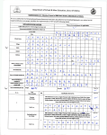
lf more than one camera is to be installed and operatedat the same time:
For example,to operatetwo camefas:set Camera 1 to Channel.j, set Came[a2 to Channel2 ,
and on the receiver,sel channels1 of 2 to ON.
For more than one camefaoperation,one image(CH1or CH2) is showedat a time withoutauto
scanningfeature.See "Carneraand ReceiverSettinqChart"belowfor detail.
CH
rFljlllt')
OR
CarrFla Sel lo
Channell
CameESel io
Channel2
Additional Notice- Vvheninstallinglhe camera,check ihe recepiionofthe receiverbeforefinal
installation.Have someoneholclthe camera in lhe area to be monitoredand anotherpersonto
check the receptionwith your TV cr mcnit.i. lf interferenceor otherprobtemsoccur,refef to the
Troubleshootingcuide.
f---------------
TechnicalData
Camera
Operatingvoltage
Receiver
7.5V DC(plug-in
powerunit)5 V DC (plug-inpowerunii)
Batteryoperation2xAA Batteryoperaiion4xAAA
Alkaline
Alkaline
200 mA
600 mA
Currentconsumption
TEnsmittinofrequencv
Modulation
Channels
Lightsensitivity
Video output level
Audio outputlevel,mono
Audio^/ideo
Connectionjacks
2.4-Ghz
2.4-Ghz
FM
3
0 Lux
3
1!E-p / 7sohm
i Vp-p/ 600ohm
3.5 mm jad(->cindl
:rc|rcSdrr
rerborlla
!!q|eo.fsc)
Picufe sensor
>>*
gTVrEftaizdtd).
Resolution
Ztr TFT
4&Y2U
a@+t-:
Picture
LOtCf
Range
@rating temperahlre
Massapprox.
(without
fipod)1579
100m/300ft
14b 12?F/ -lfc b +5O"C
/cxJJxl:,2(mm)
LXWxH
Aerial
rd)g
75 x 33 x 13O(rrn)
LxWxH
Plug-in povyerunits
r-:-----i---
vottage
llpglating
i@
Maintenance
Thedevicesarc maintenance-fee,
so Dever.open
them.Theguarantee
becomes
votdwhenyou
openrhe apptiance.onty
cteantheoutsideof theoevices
withi soft,JrV
Lrrn. pri", t"
cleaning,
removethedevices
fromallvoltage
"tit "i "
sour@s.
n
/t\
/d:.\\
Donotuseanycarboxylic
cleaning
agentsor petrol,alcoholor simita..
These.attack
thesurfaces
or tre c-eviiusees;l-;l jr;;;;;';
nazaroous
royourheatthandexptosive.
Donotuseanyjharpeogeo
toots.scrcwdivers,metalbrushes
or similarforcleanino
17.