1
1592015300 User manual iCHILL 200 L GB
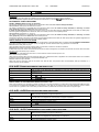
27.
28.
29.
30.
31.
32.
33.
34.
35.
36.
37.
38.
39.
40.
41.
42.
43.
44.
45.
46.
47.
48.
49.
50.
51.
52.
53.
54.
55.
56.
57.
58.
59.
60.
61.
62.
8.4
r1.0
23/02/2005
Preliminary
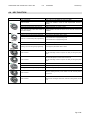
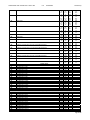
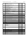
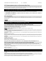
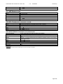
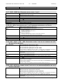
Water pump overload of condenser 1
Water support pump overload of condenser
Recovery request for circuit 1
Recovery request for circuit 2
Defrost end of circuit 1
Defrost end of circuit 2
Energy Saving
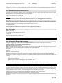
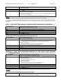
Pressure switch / compressor 1 oil
Pressure switch / compressor 2 oil
Pressure switch / compressor 3 oil
Pressure switch / compressor 4 oil
Pressure switch / compressor 5 oil
Pressure switch / compressor 6 oil
Pump down pressure switch of circuit 1
Pump down pressure switch of circuit 2
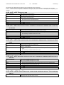
Generic alarm from digital input with stop regulation
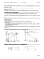
Digital input of thermoregulation request (motocondensing unit)
Digital input of cooling request (motocondensing unit)
Digital input of heating request (motocondensing unit)
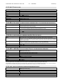
Request / partialization 1 of compressor 1 (motocondensing unit)
Request / partialization 2 of compressor 1 (motocondensing unit)
Request / partialization 3 of compressor 1 (motocondensing unit)
Request compressor #2
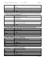
Request / partialization 1 of compressor 2 (motocondensing unit)
Request / partialization 2 of compressor 2 (motocondensing unit)
Request / partialization 3 of compressor 2 (motocondensing unit)
Request compressor #3
Request / partialization 1 of compressor 3 (motocondensing unit)
Request / partialization 2 of compressor 3 (motocondensing unit)
Request / partialization 3 of compressor 3 (motocondensing unit)
Request compressor #4
Request / partialization 1 of compressor 4 (motocondensing unit)
Request / partialization 2 of compressor 4 (motocondensing unit)
Request / partialization 3 of compressor 4 (motocondensing unit)
Request compressor #5 (motocondensing unit)
Request compressor #6(motocondensing unit)
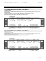
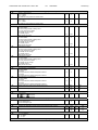
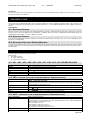
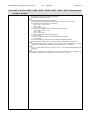
DIGITAL OUTPUT (RELAY) CONFIGURATION RL1- RL14
Parameter involved:
CF54= Configuration RL1…CF67= Configuration RL14
0. Not enabled
1. Alarm
2. Evaporator water pump / Supply fan
3. Support water pump of the evaporator
4. Anti-freeze heater / integration heating / boiler circuit #1
5. Anti-freeze heater / integration heating / boiler circuit #2
6. Water pump of the condenser recovery circuit
7. Support water pump of the condenser recovery circuit
8. 4-way valve for chiller / heat pump inversion of the circuit #1
9. 4-way valve for chiller / heat pump inversion of the circuit #2
10. Condenser fan ON/OFF control of the circuit #1
11. Condenser fan ON/OFF control of the circuit #2
12. Solenoid valve of the pump-down circuit #1
13. Solenoid valve of the pump-down circuit #2
14. Recovery valve circuit #1
15. Recovery valve circuit #2
16. Free cooling ON/OFF valve
17. Auxiliary output circuit #1
18. Auxiliary output circuit #2
19. Pulse valve for screw compressor #1
20. Solenoid valve Intermittent for screw compressor #2
21. Solenoid valve of the liquid injection for compressor #1
22. Solenoid valve of the liquid injection for compressor #2
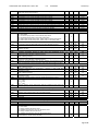
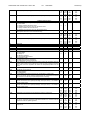
23. Direct start-up : compressor #1 relay
PW start: relay PW #1 of the compressor #1
Star-delta start: relay line #1 of the compressor #1
24. PW start: relay PW #2 of the compressor #1
Star-delta start: relay linea #2 compressor #1
25. Star centre of the Star-delta start of the compressor 1#
26. Capacity step valve #1 compressor #1
27. Capacity step valve #2 compressor #1
28. Capacity step valve #3 compressor #1
29. By-pass gas valve compressor #1start
30. Direct start: compressor #2 start
PW start: relay #1 of the compressor 2#
Star-delta start: relay line #1 of the compressor #2
Pg.26/103