1
OPERATION AND MAINTENANCE MANUAL
for
JET-EX 4D
GENERATOR SETS
Series 6854 and Series 6854A
Specification 6854-l
Specification 68548-i
Specification 68548-2
HOBART BROTHERS COMPANY
POWER SYSTEMS DIVISION
TROY, OHIO 45373
U.S.A.
Revised
Revised
Revised
Revised
Revised
Revised
Revised
Revised
Revised
Revised
Revised
Revised
Revised
Revised
Revised
Revised
Revised
Revised
OM-2007
120185
092286
100186
101686
102886
121086
012887
040187
041487
042487
051187
060587
061587
070687
080487
111887
011288
041588
081588
ELECTRIC SHOCK can kill.
Do not touch live electrical parts.
ELECTRIC ARC FLASH can injure eyes burn skin cause equipment damage and
ignite combustible material. Do not use power cables to
break load and prevent tools from causing short circuits.
IMPROPER PHASE CONNECTION, PARALLELING, OR USE can damage this and attached
equipment.
IMPORTANT: - Protect all operating personnel. Read, understand, and follow
all instructions in the Operating/InstructionManual before
installing, operating, or-servicing the equipment. Keep the manual
available for future use by all operators.
A.
GENERAL
Equipment that supplies electrical power can cause serious injury or death,
or damage to other equipment or property. The operator must strictly
observe all safety rules and take precautionary actions. Safe practices
have been developed from past experience in the use of power source equipment.
While certain practices below apply only to electrically-powered equipment,
other practices apply to engine-driven equipment, and some practices to both.
SHOCK PREVENTION
Bare conductors, or terminals in the output circuit, or ungrounded,
electrically-live equipment can fatally shock a person. Have a certified
electrician verify that the equipment is adequately grounded and learn what
terminals and parts are electrically HOT. Avoid hot spots on machine. Use'
proper safety clot.hing,procedures, and test equipment.
'The electrical resistance of the body is decreased when wet permitting
dangerous currents to flow through it. When inspecting or .4ervicing
;;;iwyo;t, do not work in damp areas. Stand on a dry rubber mat or
use insulating gloves when dampness or sweat cannot be avoided.
Keep clothing dry, and never work alone.
1.
Installation and Grounding of Electrically Powered Equipment
Equipment driven by electric motors (rather than by diesel or gasoline
engines) must be installed and maintained in accordance with the National
Electrical Code, ANSI/NFPA 70, and other applicable codes. A power
disconnect switch or circuit breaker must be located at the equipment.
Check the nameplate for volta e, frequency, and phase requirements. If
only 3-phase power is availabf e, connect any single-phase rated equipment
to only two wires of the 3-phase line. DO NOT CONNECT the equipment
grounding conductor (lead) to the third live wire of the 3-phase line, as
this makes the equipment frame electrically HOT, -m-Bwhich can cause a fata-irlzEk.Alwa s connect the grounding lead if supplied in a power line cable,
to tK e grounded switch box or building ground. If not provided, use a
separate groundin lead. Ensure that the current (am erage) capacity
of the grounding !I
ead will be adequate for the worst Pault current
situation. Refer to the National Electrical Code ANSI/NFPA 70 for
details. Do not remove plug ground prongs. Use correctly mating
receptacles.
2.
Outnut Cables and Terminals
1
Inspect cables frequently for damage to the insulation and the
connectors. Re lace or repair cracked or worn cables immediately. :Do
not overload ca1les. Do not touch output terminal while equipment is
energized.
L
3.
Service and Maintenance
; I
,.__
~,.~...-----~--This-eqP-i-pme-KEl~mu~~~e~~~~~~n~o~P~~~.rfea-l-~~~n~.me
condition to avoid hazards stemming from disrepair. Report any
_.
..,
^_._._.
_.-.-_.-.__
ecLu~~~~sr_t_.-~~f~~~.o~~~t
_-~~a~_rdtn_the-supe.rvi.s~r_and~di.srant_i_nue~
.~~___
use of the erigm ent unti$ its safety has been assured. Repairs
.____.._._...__._________._.__._.
__'
.".. .,_
~._,
. should be ma e Y qualified personnel only. ___
-._
Instruction 910082
Page 3
Feb 25186 Revised
;<
I
more inspecting or servicing electrically-powered
+zake-v~":
before inspecting or servicing the equipment.
b.
Lock switch OPEN (or remove line fuses) so that power cannot be
turned ON accidentally.
c.
Disconnect power to equipment if it is out of service.
d.. If troubleshooting must be done with the unit ener ized, have
another person present who is trained in turning of f the equipment
and providing or calling for first aid.
5 AND EXPLOSION PREVENTION
Fi 2 and explosion are caused hy electrical short circuits, combustible
ma trial near engine exhaust pi ing, misuse of batteries and fuel, or
UT3 3fe operating or fueling conii
itions.
1.
Electrical Short Circuits and Overloads
Overloaded or shorted equipment can become hot enough to cause fires
either by self destruction or causing nearby combustibles to ignite.
For electrically-powered equipment, in particular, rovide primary
*Py overloaded
input protection to remove short circuited or heave
equipment from the line.
2.
Batteries
Batteries may explode and/or give off flammable hydro en
and arcing from a ruptured battery can cause fires an8 adj;s;onzy- acid
failures. When servicing, do not smoke, cause sparking, or use open
flame near the battery.
3.
Engine Fuel
Use only approved fuel container or fueling system. Fires and
explosions can occur if the fuel tank is not grounded prior to or during
fuel transfer. Shut unit DOWN before removing fuel tank cap. Do not
completely fill tank, because heat from the e uipment may cause fuel
expansion overflow. Remove all spilled fuel 4MMEDIATELY, including any
that penetrates the unit. After clean-up, open equipment doors and blow
fumes away with compressed air.
IC FUME PREVENTION
bon monoxide - Engine exhaust fumes can kill and cause health problems.
a or vent the exhaust fumes to a suitable exhaust duct or outdoors.
3r locate engine exhausts near intake ducts of air conditioners.
ILY INJURY PREVENTION
/
,
ious injury can result from contact with fans inside some equipment.
!
t DOWN such equipment for inspection and routine maintenance. When
ipment is in o eration use extreme care in doing necessary troubleshooting;
adjustment. !I
o not remove guards while equipment is operating.
!
ICAL AND FIRST AID TREATMENT
1
i
Pi st aid facilities and a qualified first aid person should be available
each shift for immediate treatment of all injury victims. Electric
2 ck victims should be checked by a ph sician and taken to a hospital
in ediately if any abnormal signs are oBserved.
i
I
!
EMERGENCY FIRST AID
1 physician immediately. Seek additional assistance and use First Aid
hniques recommended by American Red Cross until medical help arrives.
1
I
BREATHING IS DIFFICULT give oxy en, if available, and have victim lie
FOR ELECTRICAL SHO6K turn off power. Remove victim; if not
rtificfal'respi;;tion, preferably mouth-to-mouth. If
P begrn exte
heart massage. Call Emergency
IPMENT-PRECAUT-IONAR~-------on the equi ent monthly. Order and
Labels
a e s that cannot
be easily reagm.
Pg', ;g.-y;=yQna~
Page 2
.YI
!
. ^ .:
Instruction 910082
Revised Feb 25/86
I
L
/’
i-y:- -.
This manual contains operation and service information for 28.5 V DC Generator
sets identified as Jet-Ex 4D. These units are available as stationary, skrdmounted units, or they may be trailer-mounted for portability. Both versions
are available with 14 V DC output capability.
i
I
Most information in the manual applies to the 28.5 V Jet-Ex 4D in general.;
Information which applies to options and special equipment is identified as
I
such.
I
The primary purpose of the manual is to provide information and instructions to
experienced operators, electricians, and mechanics who are not familiar wikh
this equipment. The intent of the manual is to guide and assist operators Fnd
maintenance personnel in the proper use and care of the equipment.
I
I
Read the instructions before starting the unit. Learn to use the manual and tc
locate information contained in it.
I
I
The Table of Contents, which follows this Introduction, lists all Chapters!
?
Sections, and the paragraph titles within each Section. The location of each
listing is identified by Chapter, Section and page number. A complete lisk of
illustrations, with their locations, follows the Table of Contents.
I
I
Each Chapter is divided into as many Sections as necessary. Sections are Clways referred to by a combination Chapter/Section number, for example: 2-8
I
refers to Chapter 2, Section 3.
I
!
The material within each Section is divided into main subjects with appli&ble
paragraph headings and subheadings as required. For example, a portion of the
Description Section might logically follow this arrangement and paragraphibg:
1
I
i
1.
A.
he--
!-.-I
-
I
I
Control
Interior Panel
3
I
(1) Protective devices
I
I
I
(a) Overload relay
I
I
I
(2) Contactors
I
Page numbers do not run consecutively throughout the manual. Each page is/
identifed by the Chapter/Section number in which it appears, and by a page{
number within the Chapter/Section . Therefore, the first page in each Section
is page 1. These identifying numbers appear in the lower, outside corner ok
each page. Each page also bears a date located in the corner opposite the bage
number. This date is either that of original issue, or of the latest revi!sion.
,Any revision to the original text is identified by a heavy black line in the
left-hand margin. Illustrations follow a numbering system similar to page)numbering. The first Figure in each Section is Figure 1.
f
All tables, charts and diagrams, as well as illustrations, are identified,'b
y
Figure numbers to avoid confusion.
I
1 I
Dee l/85
Introddction
I
^__--Page 1
a------,---.--
--__---__
The igenerallocation of any particular
running through the Table of Contents.
infdrmation, a quick look at the Table
Test!"is located in Chapter 2, Section
information can be found quickly by
For example: to locate any adjustment
of Contents shows that "Adjustment/
3, (shown as 2-3).
Por&ons of the text are referred to by identifying the paragraph in which the
referenced material may be found. When referenced material is located in the
same!Chapter/Section as the reference, only the paragraph identification is
giv$n, for example: (Ref. Para. 1, A) means that the material is to be found
in paragraph 1, A, of the same Section.
When referenced material is located in another Chapter/Section, both the
Chap/terand Section numbers and the paragraph identification are given, for
example: (Ref. l-2, Para. 1, A) means that the referenced material is located
in Chapter/Section l-2, and paragraph 1, A within that Chapter/Section.
/
I
Components shown in illustrations, and the illustrations themselves, are
refejrencedin a similar manner. When this type of reference is made, the item
numbierof the part and the Figure number in which it appears are given, for
examble: (2, Fig.3) refer to item number 2 in illustration Figure 3 of the
same;Chapter/Section.
j
/
!
i
,
When a referenced figure appears in another Chapter/Section, the reference will:
include the Chapter/Section number, for example: (2-3, 1, Fig. 4) tells the
:
user'that the information is in Chapter/Section 2-3, and to refer to item 1 in 1
Fig&e 4.
Once;a Figure number reference has been established, the Figure number is not
repeLted and only the item numbers of the parts involved are referenced, for
example: "Loosen screw (2, Fig.G), slide out connector (4), and remove brush
(6) 2'
1
;
When an item number is referenced without a Figure number, it always applies to:
the last preceding Figure number mentioned in the text.
A collection of manufacturer's literature is supplied as part of the informationjpackage.
,
If you have any questions concerning your Hobart Power Systems Division equip- j
menti,you are invited to contact our Service Department by mail, telephone,
or TWX.
Write:
Hobart Brothers Company
Power Systems Division
Service Department
Troy, Ohio 45373
U.S.A.
Call:
Area code (513) 339-6000
Extension 4276
TWX:
810-456-2907
I
I
i
:...”I. - ..*<--.--
-.----_
-.
r I
I Introduction
Dee l/85 i
__~___
..__.
_ __._____._.__..
_._ ._.
__._..
-____...
~._
-.-...
~.~. .-_.-.- _.I._-___.-..-..-.^-__...,
-- -_
..__
"_
L - ,_
'-.--._._
-___..
-.
:-,
Page
2 . ._..“..
,_.”._
..._ I ._
--..--.--- ..-I....-.--__-_..--- ._...-_....,._
.-..
OM-2007
__
LIST OF EFFECTIVE PAGES
CHAPTER/
SECTION
List of
Effective
Pages
Introduction
Introduction
PAGE
1 thru 2
1
2
DATE
Aug 15188
Dee 01/85
Dee 01/85
Contents
Contents
Contents
Contents
Contents
Contents
Contents
Contents
Contents
Contents
1
2
3
4
5
6
7
8
9
10
Apr
Dee
Dee
Dee
Dee
Dee
Dee
Apr
Apr
Dee
01/87
01/85
01/85
01/85
01/85
01/85
01/85
15/88
15/88
01/85
l-l
l-l
l-l
l-l
l-1
l-l
l-l
l-l
l-l
l-l
l-l
l-l
l-l
l-l
l-l
l-l
1
2
3
4
5
6
7
8
9
10
11
12
13
14
15
16
Apr
Dee
Dee
Aug
Dee
Apr
Dee
Apr
Dee
Dee
Dee
Apr
Apr
Apr
Apr
Apr
01/87
01/85
01/85
15187
01/85
01/87
01/85
01/87
01/85
01/85
01/85
15/88
15188
15/88
15/88
15/88
l-2
l-2
l-2
l-2
l-2
l-2
1
2
3
4
5
6
Dee
Dee
Dee
Dee
Dee
Dee
01/85
01/85
01/85
01/85
01/85
01/85
l-3
1
l-3
2
l-3
3
1-3
4
l-3
5
l-3
6
l-3
_-.;..
._
_.-l-3.
.~-Aug 15/88 Revised
Dee 01/85
Apr 15188
Jun 05/87
Dee 01/85
Dee 01/85
Dee 01/85
Dee 01/85
_--.
DeE.-O
r.,
8.5-
CHAPTER/
SECTION
PAGE
2-1
2-l
2-l
2-l
DATE
Dee
Dee
Dee
Dee
01/85
01/85
01/85
01/85
2-2
2-2
2-2
2-2
2-2
2-2
2-2
2-2
2-2
2-2
2-2
2-2
1
2
3
4
5
6
7
8
9
10
11
12
Dee
Dee
Dee
Dee
Dee
Dee
Dee
Dee
Dee
Dee
Dee
Dee
01/85'
01/85
01/85
01/85
01/85
01/85
01/85
01/85
01/85
01/85
01/85
01/85
2-3
2-3
2-3
2-3
2-3
2-3
1
2
3
4
5
6
Dee
Apr
Jun
Jun
Jun
Dee
01/85
15188
05/87
05/87
05/87
01/85
3-l
3-l
3-l
3-l
3-l
3-1
3-l
3-l
3-l
3-l
3-l
3-l
3-l
3-l
3-l
3-1
3-l
3-l
1
2
3
4
5
6
7
8
9
10
11
12
13
14
15
16
17
18
Dee
Dee
Dee
Apr
Apr
Apr
Apr
Apr
Apr
Apr
Apr
Apr
Apr
Apr
Apr
Apr
Apr
Apr
01/85
01/85
01/85
15/88
15188
15188
15188
15188
15/88
15188
15188
15/88
15188
15/88
15188
15/88
15188
15188
List of Effective Pages
Page 1
OPI-2007
LIST OF EFFECTIVE PAGES
CHAPTER/
SECTION
I
PAGE
DATE
4-l
4-l
4-l
4-l
1
2
3
4
Dee
Apr
Apr
Apr
01/85
15/88
15188
15188
4-2
4-2
4-2
4-2
4-2
4-2
1
2
3
4
5
6
Dee 01/85
Apr 01/87
Dee 01/85
Dee 01/85
Sept 22186
Dee 01/86
4-3
4-3
4-3
4-3
4-3
4-3
4-3
4-3
4-3
4-3
4-3
4-3
4-3
4-3
4-3
4-3
4-3
4-3
4-3
4-3
4-3
1
2
3
4
5
6
7
8
9
10
11
12
13
14
15
16
17
18
19
20
21
22
23
24
25
26
27
28
29
30
31
32
33
34
35
36
I
I
I
1
I
I
I
z
4-3
4-3
4-3
4-3
4-3
4-3
4-3
4-3
4-3
4-3
4-3
4-3
4-3
List of Effective Pages
.~
Page 2
Dee
Dee
Ott
Dee
Apr
Dee
Apr
Dee
Apr
Aug
Apr
Dee
Apr
Apr
Aug
Apr
Apr
Apr
Aug
Apr
Aug
Apr
Apr
Apr
Apr
Apr
Apr
Apr
Apr
Apr
Apr
Apr
Apr
Apr
Apr
Apr
01/85
01/85
16/86
01/85
15/88
01/85
15/88
01/85
15188
04187
15188
01/85
15188
15188
15188
15/88
15188
15188
15/88
15/88
15/88
15188
15188
15188
15188
15/88
15/88
15188
15/88
15188
15188
15188
15188
15188
15/88
15/88
CHAPTER/
SECTION
PAGE
DATE
4-3
4-3
4-3
4-3
4-3
4-3
4-3
4-3
4-3
4-3
4-3
4-3
4-3
4-3
4-3
4-3
37
38
39
40
41
42
43
44
45
46
47
48
49
50
51
52
Apr
Apr
Apr
Apr
Apr
Apr
Apr
Apr
Apr
Apr
Apr
Apr
Apr
Apr
Apr
Apr
15188
15188
15188
15188
15/88
15188
15188
15188
15188
15/88
15188
15188
15/88
15/88
15188
15188
4-4
4-4
4-4
4-4
4-4
4-4
4-4
4-4
1
2
3
4
5
6
7
8
Apr
Apr
Apr
Apr
Apr
Apr
Apr
Dee
15188
14188
15188
15188
15188
15/88
15188
01/85
5-o
5-o
Jan i2/88
Dee 01/85
6-O
6-O
Apr 01/87
Dee 01/85
Unusual Service Conditions
I
.-
Revised Aug 15188
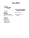
TABLE OF CONTENTS
yPAGE
CHAPTER/SECTION
SUBJECT
i
l-l
j Description/ Operation
Description
1.
General
2.
Special Features
: I
A.
Standard
B.
Options
3.
Orientation
4.
Identification
5.
Canopy
6.
Engine, Generator, and Controls
: I
A.
General
B.
Engine
(1) General
(2) Cooling fan
6
Fuel system
(3)
(4) Alternator and regulator
(5)
Starter relay
(6)
Spark arrester muffler
c.
Generator
D.
Control Panel Assembly
-6
(1) General
(2) Lights
j8
(3) Monitoring instruments
.8
(4) Potentiometer
_.^:--....i_.---_-._--
Apr
(5)
--1
18
_._
_---
_
7
R~-~~-~~~.~
Switches
.
..-
-
..--
-..---
--..-
--~-I.-
---._-.-.__I__----.
--
--
--
---
.^I
,---.-.----
_-_.
-----__l_:
Contents,
-------_-__------_----1__1
Page 1
..,
,_._
.c::-._
“.-:
CHAPTER/SECTION
--
-SUBJECT
~~.
PAGE
(6) Fuses
10
(7) Voltage regulator
10
(8) Overvoltage module
10
(9) Resistor and Diode Assembly
10
(10) Excitation Rectifiers
10
(11) Voltage Sensing Relay
10
Output Terminals
11
F. Contactor
11
G. Rectifier Assembly
11
H. Ammeter Shunt
11
7.)Optional Equipment
11
11
A. Trailer
l-2
Preparation for Use, Storage, or Shipping
1
1
l.,Preparation for Use
'1
A. General
1
B. Inspection/Check
I
:C. Output Cable Inspection
2
(1) Cable requirements
2
(2) Cable connector
2
2
2. Preparation for Storage
3
!A. General
l-2
!B. Temporary Storage
3
3
C. Long Time Storage
I
(1) Engine protection
3
/
(2) Generator protection
3
i_ .- - ._.&------~~
-.-_---
--__-_-
._--
-
----..
-.--------.-
-_~-.-____-...-.-
Dee l/85
,._ ----_----_- - _.__~__
; Contents
i.- _-_ .--_.-.------.--.-~
..._
.__._._..
~_----.__.
_.^
.,..
.._
- -.-..-..-_
-~- _-1
1...t?ag.e_
2... ^_
““”
.., -
._
6
?
.. ._ ---______--“---..
- . .._-.
TABLE OF CONTENTS (continued)
CHAPTER/SECTION
SUBJECT
3. Preparation for Shipping
PAGE
/4
I
4. Stationary Unit Mounting
I5
l-3
Operation
1
1. General
2.
11
jl
Operating the Generator Set
B. Prestart Instructions
/
;1
I
!1
C. Starting the Engine
/3
D. Generator Operation
I4
E. Deliver Power
j4
F. Stop Operation Shutdown
i4
G. Adverse Weather Precautions
!4
A. Prestart Inspection
:4
(1) Cold weather operations
(2)
Fuel system
4
(3)
Fuel
5
.
(4) Cooling system
5
(5) Lubrication
5
(6) Electrical system
5
(7) Battery
5
6
H. Operation in Hot and Humid Conditions
/ 6
(1) Cooling system
6
(2) Battery
I..A+----1”_-..^
- __-
-..------.-.-_--_
._-.--.-..._--__-
f Dee l/85
:-
-. _ .^___ _..- ._ _..“.. .,,__
- _.____.._
Page 3
.-_-.------_-.,,
~-i
SUBJECT
. Operation in Extremely Dusty Conditions
CHAPTER/SECTION
PAGE
l-3
6
(1) Fuel system
6
(2) Oil filter and air cleaner
6
(3) Crankcase
6
6
!3. Operation in Salt Water Areas
3.
(1) Canopy
6
(2) Covering
6
(3) Brushes
7
(4) Field Coils
7
(5) Battery Terminals
7
k.* Miscellaneous
7
Trailer Operation
7
dL. Towing
7
EI. Parking
7
2-l
Seri .cing
1
Maintenance Inspection/Check
1
: 1. iGenera
2.
1
3.
: 4.
'1
baintenance Schedule
1
&
General
1
B.
Maintenance Schedule
1
,c.
Time Intervals
1
iEngineand Related Components
1
'Inspectionand Cleaning
1
Maintenance Procedures
2-2
i
1
i 1. IGeneral
L..-2.....
.~~~~~ion--------------....--..
.-.,^. _ .“.”.., I_ .,..
_
Page 4
1
- .._ -
.--_____--~.__-_I_
i
_::.
--.
1
_*-
r,*L
--
O~r2007
.~
x
\’
-...-
.
TABLE OF CONTENTS (CONTINUED)
SUBJECT
/
CHAPTER/SECTION
-PAGE
2-2
jl
/
11
A.
General
B.
Lubrication Chart
c.
Generator
D.
Generator Controls
E.
Engine
I1
I
'1
(1) Lubrication schedule
i3
il
/
;3
(2) Oil specification
/
(3)
!4
Oil viscosity
j4
(4) Change engine oil (100 hours)
/
G.
(5) Change engine oil filter (100 hours)
:5
Trailer
i5
.
(1) Front axle assembly
i5
j5
(2) Wheel bearings
3.
!
I
.6
Servicing the Air Cleaner
6
A.
Cartridge Removal
B.
Cartridge Installation
.6
4.
Servicing the Fuel Filter
j6
5.
Drive Belt Service
/6
6.
Engine Cooling System
&7
7
2-2
A.
General
B.
Rust Inhibitor
/
I
1-----g
.___--_
.1 Dee l/85
_--..---
_----_.-
-.-.---.-
..--. ----__~
__-
-.-
8
TABLE OF CONTENTS (CONTINUED)
I
I
C.
SUBJECT
CHAPTER/SECTION
Antifreeze
2-2
\
PAGE
8
Battery Service
8
1.
General
8
Battery Location and Accessibility
8
Battery Care
8
Liquid Level
9
Cleaning the Battery
9
Testing the Battery
9
(1) Test with Battery Starter Tester
9
i 7.
I
b.
)
I
0.
!
/
Fe
p.
/
/
10
(2) Test with Hydrometer
j 8.
Generator Maintenance
10
B. General
10
j3. Brush Service
10
(1) Cleaning
10
Generator Revolving Field Brush Replacement
10
c.
2-3
Adjustment/Test
1.
I 2.
1 3.
1
General
1
Festing the Generator Set
1
A.
Preoperational Test Procedures
1
B.
Operational Tests
3
ioltage Regulator Adjustment
A*
28.5-Volt Adjustment
4
i3. Line Drop Compensation
4
4
- -..-_-.-__
Dee l/85
Contents
. .
_
_
_
.~
“_..--_
.
_..._-_
.-
-._-
.-_-
_,_
-
--..--.----
--.~
_......-.
-..
-
---
.-------
OMk2007
!
SUBJECT
Troubleshooting
CHAPTER/SECTION
PbGE
I
3-l
il
1.
General
/l
2.
Troubleshooting Chart
11
3.
Equipment for troubleshooting
;1
4.
Safety
5.
Diagrams
:1
I
j2
6.
Illustrations
7.
Connections and Wiring
3-l
2
;2
Illustrated Parts List
4-o
jl
1.
General
4-l
I1
2.
Purpose
il
3.
Arrangement
'1
4.
Explanation of Parts List
.l
A.
Contents
.l
B.
Parts List Form
1
(1) Figure-Item No. Column
-1
(2) Hobart Part Number Column
;2
(3) Nomenclature Column
12
(4) Eff (Effective) Column
:2
(5) Units Per Assembly Column
j2
Manufacturer's Codes
1.
4-2
Explanation of Manufacturer's (Vendor) Code List
Parts List
1.
Explanation of Parts List Arrangement
2.
Symbols and Abbreviations
Dee l/85
.- . . - ..”..,.-- ._”
:l
.1
1
4-3
!l
1
i
-j-
5 g
Colil
tents
^.__!
.
Page
j
---.
--.
-. .---....
.----__.--.-.-.----.
-_.-.d
OM-2007
TABLE OF CONTENTS (CONTINUED)
SUBJECT
CHAPTER/SECTION
Numerical Index
1.
PAGE
4-4
Explanation of Numerical Index
Optional Equipment
5-o
Manufacturer's Literature
6-O
1
LIST OF ILLUSTRATIONS
CHAPTER/
SECTION
l-l
l-l
l-l
l-l
l-l
l-l
l-l
FIGURE
NUMBER
PAGE
NUMBER
TITLE
Jet-Ex 4D Generator Set
Specifications and Capabilities
(Sheets 1 and 2)
Generator Set Components
Control Panel Assembly
(W/Shelf On Rear)
Voltage Regulator Support(Shelf Mod.)
Control Panel Assembly
(W/Enclosure On Rear)
Voltage Regulator Support(Enclosure
Model)
2
3/4
7
12
13
14
15
l-2
l-2
28 Volt Output Terminal Panel
Stationary Unit Mounting Holes
4
5
l-3
Operating Controls and Indicators
2
2-l
Inspection/Check/MaintenanceSchedule
(Sheets 1 and 2)
213
2-2
2-2
2-2
2-2
2-2
2-2
Lubrication Points
Lubricants
Symbols and Time Intervals
Temperature and Oil Viscosity Chart
Air Cleaner Cartridge Replacement
Generator Revolving Field Brushes
2-3
2-3
2-3
Operating Controls and Indicators
Idle Speed Adjustment
Voltage Regulator Adjustment
2
3
5
3-l
3-l
Generator Set Components
Control Panel Assembly
(W/Shelf On Rear)
Vo.~m~agmC
-RegulatorSupp_l,rt---
3
3-l
ContentsPage 8
.
2
3
3
4
7
12
4
_~_5
~~ ..I
.Revised.Apr 15/88
LIST OF ILLUSTRATIONS
CHAPTER/
SECTION
FIGURE
NUMBER
3-l
4
3-l
3-l
5
6
4-3
4-3
1
2
4-3
3
4-3
4-3
4-3
4
5
6
4-3
7
4-3
4-3
4-3
4-3
4-3
4-3
4-3
4-3
4-3
4-3
4-3
4-3
4-3
8
9
10
11
12
13
14
15
16
17
18
19
20
Apr I5/88 Revised
PAGE
NUMBER
TITLE
Control Panel Assembly
(W/Enclosure On Rear)
Voltage Regulator Support
Troubleshooting Chart
6
7
8-18
Generator Set (Stationary Mtg. Assy.)
Generator Set with Portable Mounting
and Fenders (Option)
Generator Set with Portable Mounting
(Option)
Canopy Assembly
Generator Set Without Canopy
Control Panel Assembly
(W/Rear Shelf)
Control Panel Assembly
(W/Enclosure on Rear)
Support, Rectifier and Fuel Tank Assy
Output Terminal Panel Assembly
Full Throttle Solenoid Assy
Battery Installation
Fuel System
Fuel and Return Lines Assy
Cooling System
Rectifier Assembly
Brushholder Assembly
Kit, Trailer, Without Fenders (Option)
Kit, Trailer, With Fenders (option)
Lifting Yoke & Frame Assembly
Generator Assembly
2
4
6
8
10
14
18
22
24
26
28
30
32
34
36
38
40
44
48
50
Contents
Page 9
This page intentionally left blank
1
I
I
-
-
---.
____-____-__--
i
I
Dee l/85 !
__-_ .---.
_._'.._^".
__
--..- --- ----_-_-.--.-
R
^‘!
ADDENDEM NO. 1
JET-EX 4D OPTIONAL PROTOTYPE TRAILER ASSEMBLY (KIT) 181000
This Addendum along with TO-181 (Chap. 5) covers Kit, Prototype Trailer with
Fenders.
Jet-Ex 4D is offered with a choice of two different trailers both of which are
optional.
Henschen Trailer With or Without Fenders Part Number 488880.
All References to the Trailer and Fenders in OM-2007 Pertain to the Henschen
Trailer.
Prototype Trailer With or Without Fenders Part Number 181000 reference this
Addendum and TO-181.
-~_.-
__________._
.
”
_. ._-
..ll_l-_-~----_.-l”.
-.
._ .~_ -
-
-------~-..---_-----_-
_.
,_._._ _-
Page-.l.
_.._-.
-
--
I -...
.
. ..--
~- _..
.~
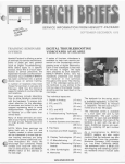
ADDENDUM NO. 1
(1) A four-wheel trailer is available to add mobility
to the generator set (See TO-181 for Details). It is equipped with
a drawbar for towing, and a hand lever actuated parking brake.
It also includes fenders that can be used as cable trays. This
option is available from Hobart Brothers as Part No. 181000-l.
(2) A four-wheel trailer is available to add mobility
to the generator set. It is equipped with a drawbar for towing,
and a hand lever actuated parking brake.
It also includes cable hangers which are mounted on the
right side of the canopy. This option is available from Hobart
Brothers as Part No. 181000-2.
Jet-Ex 4D Generator Set With Prototype Trailer
Figuce_L-. ._.
...~~~
-.-.~
~~~~__
-..----..--.
Page 2.
I
ADDENDUM NO. 1
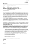
Generator Set
W/Portable Mounting and Fenders (Option)
..-._ .-- ._-.--. - -..- ._.._...______
- .-____-
.
.
.-----
.-
Li-
-.--.
-
__,.___-
___.___”
-___
I”
__-_..-
-.---------
-.._-.-.-ll_^
-.---c
p-p+@.
-.-..---
.----
.__--
-
_
-
-..-.__.--
zj
___
.____
---
______
..--- .I...
_
_ __
ADDENDUM NO. 1
NOMENCLATURE
FIGURE
ITEM NO.
HOBART
PART NO.
2-
68548-l
181000-I
1234567
GENERATOR SET W/ PORTABLE MTG.
AND FENDERS (OPTION)
TRAILER, ASSY, (OPTION)
or Details See TO-181)
. . REFLECTOR, RED
. . FENDER, LEFT OPTION
. . FENDER, RIGHT OPTION
. . BRACKET, MTG. FENDER
(RT FRONT & LT REAR)
OPTION
. . BRACKET, MTG. FENDER
(LT FRONT & RT REAR)
OPTION
. . BRACKET, MTG. FENDER (RT CENTER) OPTION
. . BRACKET, MTG. FENDER (LT CENTER) OPTION
. . SUPPORT, FENDER REAR
OPTION
. . SUPPORT, FENDER FRONT
OPTION
l
408665-I
181006
181007
181010
6
181009
7
"8
9
10
181013
181011
181008
181012
UNITS
per
ASSY
1
(F
2
Page 4
_~ -1
^.. .
._
-- -- - .- - -..._
-.. _-~--_
._._~*--.-._
ADDENDUM NO.1
3
I
f7
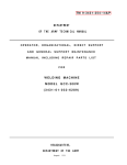
Generator Set W/Portable Mounting (Option)
Figure 3
j
,/
,,
.,
.. '.
,.
.'
_
,'/' .._
-. _.-_.___.----.
-_
..
___-~___-
-_ -.--.
ADDENDUM NO. 1
NOMENCLATURE
FIGURE
ITEM NO.
HOBART
PART NO.
3-
6854~-1
1
181000-2
2
3
85B-1013
DWP-982
UNITS
per
ASSY
1234567
GENERATOR SET JET-EX 4D WITH
PoRTABLE MTG. (OPTION)
TRAILER ASSY., (OPTION)
or Details See TO-181)
. . TIRE, 5:30 X 12, WHEEL ASSY.
. . BRACKET, CABLE
l
(F
4
2
* Not Illustrated
Page 6
CHAPTER 1. DESCRIPTION/OPERATION
SECTION 1. DESCRIPTION
The Jet-Ex 4D unit covered in this manual (Figure 1) is a diesel engine
driven, self-contained generator set manufactured by Hobart Brothers
Company, Power Systems Division, Troy, Ohio U.S.A. The basic unit is 1
identified by a Series Number - either 6854 or 6854A - plus a dash number
which defines a specific configuration. The Series-number, plus the dash
number, make up the Specification Number.
:
Specification No. 6854-l - or Specification No. 6854A-1 - covers a
stationary, skid mounted unit rated at 28.5 Volts DC output. It is
equipped with a sheet metal canopy and hinged engine compartment door.:
Various options are available for use with the basic unit. These options
are listed in paragraph 2.B. below.
The generator sets in Series 6854A are identical in appearance, construetion, and electrical operation to Series 6854 generator sets. They differ
i
from Series 6854 generator sets in that, in Series 6854A units, the
tachometer sending device is eliminated, a different tachometer is used,
and a different brand of alternator is used.
The basic generator set is designed to generate and deliver 28.5 volts DC
power to an aircraft when its on-board generators are shut down. In 1
addition to poviding continuous, regulated power to the aircraft, the unit
is designed for starting any fixed-wing aircraft or helicopter which is
equipped with an external 28.5 volt DC power receptacle. Refer to Figure 2
for complete Specifications and Capabilities.
2.
Special Features
A.
Standard
The "Soft-Start" current limiting feature, recommended by most engine
manufacturers, provides the operator with a control which limits the
inrush current to the aircraft engine's starter. When the operator
presets this control, the generator will provide constant voltage to
the preset currrent value. As more current is applied beyond the 1
preset current value, the voltage will decrease to a minimum of 14
volts DC, after which the voltage will remain constant as more current
may be delivered beyond the preset current value. Limiting inrush:
current is recommended by most engine manufacturers to protect the;
aircraft engine's starter shear section. The current limiting control
is continuously adjustable from 300 amperes, which is recommended for
helicopter and small turbine starting, to 2000 amperes, required for
starting larger aircraft engines when the control is turned fully :
clockwise.
Revised
Apr
l/87
_.
_. .- ..__
- --~
..__..
~..
--
-
"_,...
-__.____
- .-______ L-l.zL
-.-.
---.-----_
.-.
- _-_-_--_...
..-_
_-_-_.____I__
*age--=&
/
\
+- - ,-rf..- -_,_..__. IT-,
.-~7-“-;I
*’
,<,.
,(
”
;
‘.,
I
OM-2007 j __-.
‘*,~..-,/
..-__ ..---.__-_..'
._
-_-__.-..____
~~--.--..-.__---.-----.-----_- -------_._I.,/-
.
Jet-Ex 4D Generator Set
Figure 1
t,__-- ,-
%- .‘“-a
-
-----__-
j l-1 1
-.-..-- .------..-.-----.--____.__,_-._ .__.
_.
_ ..__--._.
-..._--_- .._._ ., _-_.
*
I
I
/-
I
Dee l/85 [
I
I
‘\I
i/
UNIT WITH CABLE HANGERS & SPACERS UNDER FRAME
Length
Width
Height
Weight (dry fuel tank)
I
65.75
34.25
53
1900
inches (1670 mm)
inches (870 mm)
inches (1346 mm)
pounds (862 kg)
UNIT WITH TRAILER AND CABLE HANGERS (Without Fenders)
Length
Width
Height
Weight (dry fuel tank)
Ground Clearance
78.75
54.5
57.5
2125
3.625
inches (2000 mm)
inches (1384 mm)
inches (1461 mm)
pounds (964 kg)
inches
(92 mm)
79.75
56
57.5
2280
3.625
inches
inches
inches
pounds
inches
UNIT WITH TRAILER, FENDERS AND CABLE TRAY
I
Length
Width
Height
Weight (dry fuel tank)
Ground Clearance
(2026 mm)
(1422 mm)
(1461 mm)
(1034 kg)
(92 mm)
GENERATOR
Output Power Rating
15.7 kW
Voltage
28.5 volts DC
Rated Load Capacity
550 amperes continuous at 28.5 volts DC
Starting Current Capacity
2000 amperes maximum
Current Limiting Capability
300 to 2000 amperes, continuously adjustable
Operating Speed
2600 RPM
ENGINE
Manufacturer
Model
Perkins Diesel
4.236
4-cylinder, 4-stroke, direct injection
Fuel
ASTM D97.566T Numbers 1D or 2D
Displacement
236 cubic inches (3.86 liters)
Rated Power at 2400 RPM
77 Horsepower
Oil Capacity (with filter change)
8 quarts (7.57 liters)
Coolant Capacity
3.5 U.S. gallons (13.25 liters)
Type
Specifications and Capabilities
Figure 2 (Sheet 1 of 2)
cm--Dee l/85
l--.I
--
L-----------
.-.-_,--_----.--
i I
; l-l
t
Page 3
OM-2007
Electrical System
Governed Speed at No Load
Idle Speed
Fuel Tank Capacity
12 volt DC, negative ground
2600 + 50 RPM
1000 + 50 RPM
21.5 U.S. gallons (81.4 liters)
PROTECTIVE DEVICES
GENERATOR
28.5 volt overvoltage module trips at 32 to 34 volts.
14 volt overvoltage module trips at 18 to 20 volts.
ENGINE
Water Temperature Switch opens engine circuit at 225°F.
Low oil pressure switch opens at 20 PSI (138 kPa).
Specifications and Capabilities
Figure 2 (Sheet 2 of 2)
B.
Options
(1) A four-wheel torsional spring trailer is available to add mobility
to the generator set. It is equipped with pneumatic rubber tires,
a drawbar for towing, and drawbar-operated, drum type parking
brake. It also includes fenders, bumpers and cable trays. This
option is available from Hobart Brothers as Part No. 488880-3.
(2) A four-wheel torsional spring trailer is available to add mobility
to the generator set. It is equipped with pneumatic rubber tires,
a drawbar for towing, and drawbar-operated, drum type parking
brake. It also includes cable hangers which are mounted on the
right side of the canopy. This option is available from Hobart
Brothers as Part No. 488880-4.
(3) For mounting the generator set as a stationary unit, a stationary
mounting kit is available. This kit, identified as part number
489689, consists of four spacer brackets which support the unit
and permit anchoring it to a floor or platform, screws for fastening the spacer brackets to the unit, and two cable hanger brackets.
3.
Orientation
The radiator end of the Jet-Ex 4D is the front. Right and left are
determined by standing at the rear of the unit, facing it. The control
panel is located at the rear.
I
l-l
Page 4
Revised Aug 15/88
-. .-
4.
Identification
The Jet-Ex 4D unit is identified by Specification numbers as described in
paragraph 1, above. There may be any number of generator sets with the:
same Specification number. Individual machines are identified by a Serial
number, assigned to one machine only.
Each generator set has an Identification plate attached inside the hinged
control panel door. This nameplate lists the machines's Model No. (Jet-Ex
4D), Specification No., Serial No., and electrical rating.
If any of the options described in paragraph 2. B. are included, they will
be listed by name and part number on a separate option nameplate located
I
next to the Identification plate.
5.
Canopy
The standard canopy is a sheet metal enclosure which protects the engine,
generator, and electrical controls. It has two hinged doors on each side
at the front to provide access for service and maintenance. Panels at :the
rear provide access to the generator. A Plexiglas window is mounted above
the control panel to allow observation of the instruments while protecting
them from the weather. The left rear panel has a round hole in it to
permit viewing the fuel gage mounted in the fuel tank.
6.
Engine, Generator, and Controls
A.
General
Refer to Figure 3. The engine (4) and generator (9) are mounted on a
welded steel frame (20). A fuel tank support (21) located at the rear
of the unit supports the fuel tank (7) and provides a mounting frame
for the load contactor (14) and output terminals. The radiator (1) is
mounted to the front canopy. A heavy U-bolt is attached to the centrally located lifting yoke (5) for moving the generator set with a
crane or hoist.
B.
Engine
(1) General
.
The engine used in the Jet-Ex 4D generator set is a Perkins
four-cylinder, four-stroke, direct injection diesel engine. It has
a 236 cubic inch (3.86 liter) cylinder displacement and a 16:l
compression ratio. Engine firing order is l-3-4-2.
-..
:Dec
.:
--_l/85
..-~
..._
-
s. -I,
.-.
._ I ....- ~.
^
I l-11
.-.-_
. .____
.~
_____...
. .._
__.
--..
.---.-.------._.__-._.._
- ------.
.--_-..____
-____
----I----_-_
___------------Page-&
A spring-loaded relief valve in the pump limits maximum pressure
in the system. A full-flow oil filter (12, Figure 3) cleans the
entire output of the pump before it enters the oil distributing
system. A valve in the filter provides a bypass to an oil gallery
in case the filter becomes clogged. A low oil pressure switch is
mounted on the engine block as a protective device. The primary
ignition circuit is wired through the contacts of this switch,
which closes at 20 PSI (138 kPa). This prevents the engine from
running if oil pressure will not build up, and also shuts down the
engine if oil pressure drops radically during operation.
:
i
I
5
:
i
;
j
i
!
See Figure 2 and the engine operator's manual for engine
specifications.
The generator and engine are mounted on a welded steel skid, and
are enclosed by a sheet metal canopy that bolts to the skid.
Access to engine serviceable components (oil filter, air
cleaner, and rectifier assembly, etc.) is through two doors at
the front on each side of the machine.
Two removeable panels to the right side and one to the left rear
allow access to the other components such as the load contactor
and output terminals. The rear panel is removeable and permits
access to the rectifier assembly.
Cooling fan
(2)
The cooling fan on the engine is designed to blow air out
through the radiator rather than to draw it in. This prevents
hot air, heated by the engine, from entering the generator.
(3) Fuel system
The fuel system consists of an 21.5-gallon (81.4 liters) tank
(7, Figure 3) with all the necessary fittings and hoses.
(4) Alternator and regulator
The battery charging alternator (16, Figure 3) is rated at 42
amperes on Series 6854 generator sets and at 62 amperes on Series
68548 generator sets. The voltage regulator is an integral part
of each of these alternators.
(5)
Starter relay
The starter relay (19, Figure 3) is mounted on the starter motor
on the right side of the engine.
(181,
Exhaust muffler (3, Figure 3)
(6)
This muffler helps deaden audible noise from the engine's
exhaust.
I
“I,..l_..-.-._
._.
: J-1 ;
!J?.age
6
Revised Apr l/87/
-.
.-,
._
_
_.
---.-
-
----_---_I___
2k
I! Ii lbi,
LEFT SIDE VIEW
‘4,
..’
21’
-15
I
I
20
I
I
I
I
9
19
\
\
\
I8
17
16
RIGHT SIDE VIEW
I
1.
2.
3.
4.
5.
6.
7.
8.
9.
10.
11.
12.
13.
14.
E
1
Radiator
Air cleaner
Muffler
Engine
Lifting yoke
Rectifier assembly
Fuel tank
Control panel
Generator
Fuel filter
Throttle control solenoid
Oil filter
Drain cock
Load contactor
14.
15.
16.
17.
18.
19.
20.
21.
22.
23.
24.
Load contactor
Batteries
Alternator
Fuel filter
Starter
Starter relay
Frame
Fuel tank support
Engine governor
Water temperature sender
& switch
Oil pressure sender
& switch
I
/
/
5
Generator Set Components
Figure 3
Dee l/85
,.----L--------
-___
-------
I
Page 7
i
‘,
_>’
’ -.
,. -’
__
,/’
--._
‘=-,,,
._
,_I
/(
A’-
i*-y >,,
..--.._
,-
1
--..-
._-.-.
^....
-
__
.
..-.
-
_, ..,.L’.-
_-
I_ .. ’
-.,.
--.,
_^
_
‘..
_
_
.c.
Generator
The generator (9, Figure 3) is a multi-phase, synchronous salient
pole, revolving field, AC generator whose output is rectified. The
output is rectified by a rectifier assembly (6) made up of twelve
rectifiers connected into a full wave configuration. The generator is
self-excited and receives excitation from a three phase full wave
rectified stator winding. One positive and one negative brush in
contact with slip rings supply controlled excitation current from the
stator winding through the voltage regulator to the rotating field
winding. The voltage regulator controls the excitation current and
maintains a constant output voltage. Access to the brushes is through
holes in the anti-drive end bracket. The rotor is supported at the
anti-drive end (slip ring end) by a single-row ball bearing. The
drive end is connected to the engine fly-wheel by a flexible disc and
hub coupling assembly and is supported by the engine main bearings. A
radial-blade fan of formed and welded sheet metal construction is
mounted on the coupling hub and draws cooling air over the generator
windings.
Air enters through the anti-drive end of the generator and is
discharged through openings in the flywheel housing at the drive end,
to cool the rectifier assembly above it. The generator housing
assembly, which contains the generator stator, is bolted to the engine
flywheel housing.
D.
Control Panel Assembly
(Figure 4)
(1) General
The hinged control panel (8, Figure 3) houses and provides
mounting facilities for controls, monitoring instruments, voltage
regulator, relays, etc. The panel is mounted at the rear of the
canopy. Its control are accessible behind a hinged Plexiglas
cover.
(2) Lights
Two panel lights (7, Figure 4) provide illumination for
instruments and controls. One green pilot light (12) glows when
the output load contactor is closed, and another one (14) glows
green when the engine is running.
(3) Monitoring instruments
The voltmeter (6, Figure 4) indicates generator output voltage,
and the ammeter (5) displays generator current.
A tachometer (2) displays the engine speed in RPM. On Series 6854
units this instrument is operated by tachometer sender mounted on
the engine governor (22, Figure 3). On Series 6854A units, there
is no sender, and the tachometer receives its opera:ing signal
from the alternator.
:1
_....
_.
_:..-__.-._-_---_-
Revised Apr l/87 :_____
_---l.---__.----_.---
1
A water temperature gauge (3) indicates the engine coolant
temperature and is actuated by a temperature sender (23, Figuke 3)
mounted on the engine's water jacket.
I
I
An oil pressure gauge (1, Figure 4) displays the pressure in ihe
engine's lubrication system. It is operated by a sender (24,;
Figure 3) mounted on the engine block.
I
I
The ammeter (20, Figure 4) indicates the rate of charge or - ;
discharge in the engine's 12 volt DC electrical system.
1
/
The hourmeter (15) records the total hours of engine operation fol
r
scheduling maintenance.
I
I
(4) Potentiometer
I
I
The current limiting potentiometer (4) is used to select the ktart
ing current recommended for various aircraft. The current 1iptiI
setting is continuously adjustable from 300 to 2000 amperes. ,
I
I
(5) Switches
I
./
The contactor control switch (11, Figure 4) is a three-positi,on
toggle switch used to close and open the output load contactor.
The top CLOSE position is spring-loaded and is held momentariily
until the contactor closed light (12) glows, then it is released
to the center ON position. In this position the switch provildes
I
holding current to the load contactor to keep it closed.
Protective devices in the load contactor circuit provide prot/ectic
against overvoltage by opening the load contactor if that
condition occurs. In the bottom OFF position, the contactor !is
opened. The push-to-build-up-voltageswitch (10) is a momentary
contact pushbutton switch which flashes the generator fields lwith
1
12 volt engine circuit when flashing the fields.
I
I
I
The panel lights switch (8, Figure 4) turns the lights (7) 04 and
1
off. The engine start switch (17) is a momentary contact
pushbutton which closes the starter relay (8, Figure 3) and drank:
the engine. This switch is operable only when the engine swifch
(19) is held in its top spring-loaded START position.
I
The engine switch (19), when released from its top START position
after the engine starts, will return to center RUN position.1 The
engine ON light (14) will glow as long as the switch is in RUN
position. In the bottom STOP position, the switch will stop!the
I
engine and the light (14) will go out.
/
I
Refer to Figure 4. The speed control switch, (13) is a
two-position toggle switch wired to an idling device on the 4nginl
In the IDLE position, used for starting, the engine speed is;
controlled approximately. In the Rated RPM position, enginelspeec
I
is controlled to approximately 2600 RPM.
.,-_,.--
i1
I l-:
I
-------
Page !
L---.
Dee l/85
I--_
I
-.
b----------.--
I
(6) Fuses
Three cartridge-type fuses protect the engine ignition circuit, thei
panel lights circuit, and the voltage regulator. The engine cir- i
cuit fuse (13, Figure 4) is rated at 20 amperes, the panel lights 1
fuse (9) at 10 amperes, and the voltage regulator fuse (4, Fig. 5) ]
at 10 amperes.
I
I
(7) Voltage regulator
Refer to Figure 5. The voltage regulator (1) is a solid-state
device which regulates the 28.5 volt DC generator output after the ]
voltage is built up.
I
(8) Overvoltage module
I
The overvoltage relay (2) is a solid-state protective device on a i
printed circuit board. A normally closed relay in the circuit is ,
wired into the load contactor coil circuit. An overvoltage condi- ;
tion causes the relay contacts to open, which in turn prevents the,
contactor from closing, or opens the load contactor and disconI
tinues the power delivery. The overvoltage module is adjusted to f
to trip at 32 to 34 volts DC in 2 to 10 seconds.
I
.I
I
(9) Resistor and diode assembly
This network, which is mounted on a terminal strip behind the
control panel, protects the load contactor hold circuit against
excessive current draw when the generator is delivering power.
r
1
I
I
(10) Excitation rectifiers
;
Two diode bridge rectifiers, CR418 and CR418, (3, Fig. 5) convert /
an AC voltage from the generator armature to the DC voltage need- j
ed for the generator revolving field.
I
(11) Voltage sensing relay
Voltage sensing relay K406 (5, Fig. 5) is a safety device which
automatically opens the grounding circuit of the revolving field
to prevent excessive voltage build-up if the push-to-build-upvoltage switch is held in too long, or if it is pushed in after
voltage is built up.
{
i
/
f
I
I
1
I----;
L-.
I
1-l
,--
i
.i --
t-?!%e_20_------
; 1
Dee l/851
I
-----.--p
I
1
I
I
I
The load contactor, which is mounted behind the control panel on $he
fuel tank support, provides a safe and convenient means of connecting
and disconnecting the generator from the load. Initial power for;
closing the load contactor is supplied by the generator through the
spring-loaded momentary contacts of the contactor control switch (11,
Figure 4). Holding power, to keep the contactor closed, passes t$roug
I
the normally open auxiliary contacts in the load contactor.
I
Output Terminals
-i
I
E.
Contactor
F.
The output terminal panel is mounted inside the unit just behind the
control panel. The positive terminal is the A2 terminal of the 1Pad
contactor, and the negative terminal is to the right of the load conI
tactor.
I
7.
G.
Rectifier Assembly
I
1
The rectifier assembly (6, Figure 3) is located at the center of bhe
machine on the fuel tank support. It consists of two aluminum hebt
sinks with twelve diodes on each heat sink. The negative heat sib
assembly is mounted nearest to the fuel tank, and the positive hyt
sink assembly is mounted nearest to the engine. The rectifier ,
f
assembly converts the AC output of the generator to 28.5 V DC.
H.
Ammeter Shunt
I
t
I
The ammeter shunt is connected in the generator's negative outpud
circuit. It supplies a small voltage proportional to output current
for operation of the generator ammeter (5, Fig. 4) and for sensidg
output current for the current limit circuit of the voltage regulator
(1, Fig. 5). This shunt is mounted on the negative heat sink ofithe
rectifier assembly (6, Fig. 3).
I
I
I
Optional Equipment
I
I
I
A. Trailer
I
The portable JetrEx 4D is mounted on an optional four-wheel trailer
(see Figure 1) which consist of front and rear axle assemblies. The
axles are mounted directly to the main frame of the generator set! It
is available with or without the fenders, bumpers and cable trays: The
front axle is a solid beam type. Front wheels are mounted on spindles
which are operated by tie rods connected to the hitch and drawbar;
assembly. The spindles are mounted to the axle by means of torsional
I
springs.
Any side-to-side movement of the drawbar turns the wheels in the 1
direction of travel. The drawbar can be folded upward and locked;in
the vertical position when the trailer is parked. When the drawb:r is
raised, it applies the brakes on the rear wheels.
I
Dee l/85
OM-2007
TACHOMETER
OIL
1.
2.
3.
4.
5.
6.
7.
8.
9.
10.
PRESSURE
WATER
TEMP
Oil Pressure Gauge
Tachometer
Water Temperature Gauge
Current Limit Control
Ammeter (Generator)
Voltmeter
Panel Light
Panel Lights Switch
Panel Lights Fuse
Push-To-Build-Up-Voltage Switch
11.
12.
13.
14.
15.
16.
17.
18.
19.
20.
Contactor Control Switch
Contactor Closed Light
Speed Control Switch
Engine On Light
Hourmeter
(deleted)
Engine Start Switch
Engine Circuit Fuse
Engine Circuit Switch
Ammeter (Engine)
Control Panel Assembly
(W/Shelf On Rear)
Figure 4
l-l
Page 12
1
-Revised Apr 15188
OM-2007
The rear axle is also a solid beam type. The rear wheels are mounted
to the axle by means of torsional springs and they have drum-type
brakes.
I
TOP
3
VIEW
4
\
BOTTOM
VIEW
2
1. Voltage Regulator
2. Overvoltage Relay
3. Excitation Rectifiers
4. VolltageRegulator Fuse
5. Voltage Sensing Relay
Voltage Regulator Support
(W/Shelf On Rear)
OM-2007
2
3
4
6
5
I
7
\
\
\
bwl.r =v
\
0
\o
STARTIN
‘GENERATOR -
CURRENT
Gs
io
1.
2.
3.
4.
5.
6.
7.
8.
9.
10.
19
/
I8
17
Ii
I5 I 13
14
Oil Pressure Gauge
Tachometer
Water Temperature Gauge
Current Limit Control
Ammeter (Generator)
Voltmeter
Panel Light
Panel Lights Switch
Panel Lights Fuse
Push-To-Build-Up-Voltage
P
Switch
11.
12.
13.
14.
15.
16.
17.
18.
19.
20.
’
II
6
IO
'8
9
Contactor Control Switch
Contactor Closed Light
Speed Control Switch
Engine On Light
Hour-meter
(deleted)
Engine Start Switch
Engine Circuit Fuse
Engine Circuit Switch
Ammeter (Engine)
Control Panel Assembly
(W/Enclosure On Rear)
Figure 6
l-l
Page 14
-Revised Apr 15188
OM-2007
1.
2.
3.
4.
5.
Excitation Rectifiers
Voltage Sensing Relay
Overvoltage Relay
Voltage Regulator
Voltage Regulator Fuse
Voltage Regulator Support
(W/Enclosure On Rear)
Figure 7
Apr 15188 Revised
~~
l-l
Iage
15
OM-2007
This page intentionally left blank.
l-l
Page 16
Revised Apr 15188
SECTION 2. PREPARATION FOR USE, STORAGE, OR SHIPPING
1.
I
I
Preparation for Use
A.
i
I
General
The generator set is shipped with dry batteries and an empty fuel tar&.
After the batteries are filled with electrolyte and charged, the fife1
tank filled and the generator set inspected, the generator set is ready
for use.
CAUTION:
READ OPERATING INSTRUCTIONS IN SECTION l-3 BEFORE OPERATFNG
THE UNIT.
I
I
B.
Inspection/Check
I
Inspect the unit completely prior to operation.
(1)
(2)
t
(3)
(4)
Remove crating, blocking, banding, ties, and other securing ahd
protective material. After shipping carton is removed, remove the
four carton supports from the bases of the clearance lights. I The]
install the attached clearance light lenses in their bases. 1
I
Inspect exterior for shipping damage such as broken glass, da/magec
sheet metal, etc.
I
Open canopy door and inspect interior for foreign material such af
I
rags, tools, shipping papers, etc.
I
Check fuel, coolant, and oil hoses and connections for visible
leaks. If leaks are discovered, correct by tightening'hose i
clamps, tube fittings, etc., as required.
I
(5)
Check security of attaching and retaining hardware.
(6)
Check the following for sufficient quantity.
(a)
Fuel
Fuel tank capacity is 21.5 gallons (81.4 liters).
I
(b)
i
I
I
Engine coolant
I
I
I
The radiator cap is located above the front canopy.
Coolant level should be approximately one inch below the
filler neck. Allow a sufficient capacity for coolant
:
expansion.
f
CAUTION:
Use
BE SURE THE COOLING SYSTEM ANTIFREEZE SOLUTIO' IS
r
ADEQUATE TO PROTECT BELOW LOWEST TEMPERATURE ,
EXPECTED.
i
c---.
Dee l/85
-h------
--.----.__
--
._II__-___-___
-_--_
----- .___-
Page 1
(c)
Engine lubricating oil
I
I
/
The oil level dipstick is located on the right side of the
engine. Refer to Perkins User's Handbook for oil
recommendations.
(7)
I
I
/
I
Make sure air cleaner element is installed. Recommended
replacement element is Donaldson Duralite Element No. PlO-1222
(Hobart Part No. 408436)
(8) Check fluid level in 12 volt batteries.
.
i
/
Fluid should cover plates. i
I
/
I
I
I
Output Cable Installation
Units are normally supplied without a generator-to-aircraft
(1)
cable.
Cable requirements
Cable length is determined by the customer's requirements.
It is recommended that the cable be no longer than 30 feet
(9 m>. The cable should be two conductor with lug-type
terminals on one end and an AN-2551 plug connector on the
other.
The recommended single conductor sizes for 28.5 volt DC,
continuous rated amperage and 90°C (194'F) rise is as
follows:
for 285 amperes use 2/O size
for 385 amperes use 4/O size
for 530 amperes use 350 MCM size
NOTE:
Some operators may wish to add a second cable assembly
with MS-25019 plug connector for starting aircraft
such as Jetstar and Sabre liner.
1
I
I
(2) Cable connector
2.
(a)
I
Connect 28 volt conductors to output terminals on output
terminal panel (Figure 1). Connect POSITIVE cables to output;
(lower) terminals of load contactor. Connect NEGATIVE cables;
to vertically-mounted bus bar.
I
(b)
Store cables in cable tray provided on top of fender, or
on hangers on side of canopy if fenders are not used.
1
/
I
I
reparation for Storage
I
I
f
hen a generator set is to be stored or removed from operation, special
recautions should be taken to protect the internal and external parts from:
ust and corrosion.
I
I
_c _-_--_
LJ2a~e2-----....-
_-_-_--
Dee l/85 i
i
B.
(1)
The unit should be prepared for storage as soon as possible after
being removed from service.
(2)
Storage should be in a building which is dry and which may bei
heated during winter months.
(3)
Moisture absorbing chemicals are available for use where excessive
dampness is a problem, however the unit must be completely
packaged and sealed if moisture absorbing chemicals are to be:
effective.
Temporary Storage
When storing the unit for one month, prepare as follows:
c.
(1)
Lubricate the unit completely in accordance with instructions, in
Section 2-2. This will include changing engine oil, and filter
elements.
(2)
Make certain the cooling system antifreeze solution is adequate to
protect below the lowest temperatures expected during the storage
period.
(3)
Clean the exterior of the engine with fuel oil and dry with clean
cloths and compressed air.
(4)
Seal all engine openings. Use a waterproof, vaporproof material
which is strong enough to resist puncture damage from air
pressure.
Long Time Storage
(1)
Engine Protection
The Jet-Ex 4D generator set may be stored for long periods if the
engine is given proper protection from rust and corrosion. Refer
to the Perkins Diesel Users Handbook (Series 4.236) for proper
procedures to be followed.
(2)
Generator Protection
To protect the generator and other electrical components, the
complete unit should be packaged, using moisture proof
packaging and sealing materials.
Place packages of moisture'
absorbing chemicals, such as silica-gel, in the unit before
packaging.
WARNING:
]-
._-
-. +--
----._.
-.---.-
__-__._.
PLACE WARNING TAGS IN SEVERAL PLACES TO MARE CERTAIN
THAT THE INDIVIDUAL WHO TARES THE UNIT OUT OF STORAGE
IS WARNED THAT ENGINE OIL AND COOLANT HAVE BEEN
.;
DRAINED.
j
/
f
___
I
i Dee l/85
-..-:...- ---_. . ...------.
.-__,
_.___.____ ._._._-._ ..-.___._ _.-
:-'.
1
:..__.. ___^"_
_
:
1-j
Page
d
..--.
.- ..-..
_..____.___ - ..-.._
--- _._
_!
(3)
Battery Care
Remove batteries and store in a cool dry place. Store the
batteries on wood rather than directly on cement or metal.
3.
reparation for Shipping
repare the unit for shipping as follows:
Seal all engine openings to prevent the entrance of water, dirt, and
dust.
.
Disconnect battery cables.
Drain all fuel from tank and fuel lines as required by carrier rules.
Crate the unit solidly to prevent damage to instruments, glass, and
sheet metal.
1
i-
I-
A-2
‘3
:
-
c
IPSD-I1381
1.
2.
3.
Positive Output Connection
Negative Output Bus Bar
Load Contactor
28 Volt Output Terminal Panel
Figure 1
Dee l/85
[email protected]
--.-----
4.
Stationary Unit Mounting
Figure 2 illustrates the mounting hole pattern in the base of the
stationary Jet-Ex 4D generator set. Each of the eight holes is 11/16"
(17.5 mm) in diameter.
13y
t-----
--
-----
---
e
I
,
---_
,
II
4,
1
----__-
---
-___-
o----eh
I
eu
26”
e
v-
I
-&-__--------_-
:,
-..-.-&--I
----AL-----L
-
-.-------Q---L_-------
Stationary Unit Mounting Holes
Figure 2
:
“I
:.
__
“_
_,_.x_--^
..-_------_
: Dee l/85
._
_
-..;-.--....___
___~-.
___
~.
-...~._
l-2
Page 5
This page intentionally left blank.
(__ _ _.. - A---
.---
_____
--__-
- _____._-
-..--.--.
-.--
__-.+L
4
l-2 ;
Dee l/85 i
:
L _. _ ...i.-.
_-_.
_-.._
.-_...
-_..-.-.____.___
~.._
.._-.
.___.
.__._,...
_ - ...._..---~--.--- ^ .---.-.
..-..
- -...-..
_---..
!
f Page 6
.. " .-. ._..,,
..._.-~. _
------.
-- _......
-.-.-_-._-_-.._-_~...^.,.
-,
OM-2007
SECTION 3. OPERATION
1.
General
This section contains information and instructions for the safe and
efficient operation of the generator set. Operating instructions are
presented in a step-by-step sequence of procedures to be followed in
supplying power to an aircraft.
NOTE:
Read ALL of the operating instructions before attempting to operate
the equipment.
WARNING:
2.
EAR PROTECTION MAY BE NECESSARY WHEN WORKING CLOSE TO THIS
EQUIPMENT.
Operating the Generator Set
A.
Pre-start Inspection
B.
(1)
Always be sure there is sufficient oil and coolant in the engine.
(2)
Be sure the fuel shutoff valve is open. The valve is located at
the fuel tank outlet. Observe the fuel gage. Make certain of
sufficient fuel to complete the job to be done.
(3)
If the unit is trailer mounted and is not connected to a tow
vehicle, be sure the parking brake is applied and that the drawbar
is raised and locked in the vertical position. Raising the
drawbar to the vertical position automatically applies the brakes,
and they will be released when the drawbar is lowered.
(4)
Open the engine compartment doors and inspect interior for rags,
tools, and foreign material.
Pre-start Instructions
In all probability, the unit will be moved from one location to another
many times during its lifetime of service. Therefore, the following
steps should be taken to optimize maximum efficient operation.
Dee l/85
(1)
Check the supply of fuel, crankcase oil and radiator coolant.
Perkins Engine User's Manual for specifications.
(2)
Inspect the unit thoroughly to be sure it is in proper working
order. Check all fuel lines and wire connections to be certain
they are secure. Tighten any loose screws, nuts or bolts.
(3)
Wipe off the entire unit and clean the air passages, control panel
and other hard to reach places with compressed air not over 25 psi
(172 kPa).
See
1-3
Page 1
OM-2007
6
7
GENERATOR -
Ips]
1.
2.
3.
4.
5.
6.
7.
8.
9.
10.
Oil Pressure Gauge
Tachometer
Water Temperature Gauge
Current Limit Control
Ammeter (Generator)
Voltmeter
Panel Light
Panel Lights Switch
Panel Lights Fuse
Push-To-Build-Up-Voltage
Switch
11.
12.
13.
14.
15.
16.
17.
18.
19.
20.
Contactor Control Switch
Contactor Closed Light
Speed Control Switch
Engine On Light
Hourmeter
(deleted)
Engine Start Switch
Engine Circuit Fuse
Engine Circuit Switch
Ammeter (Engine)
Operating Controls and Indicators
(Rear Shelf & Rear Enclosure Models)
Figure 1
l-3
Page 2
Revised Apr 15/88
-.
.,.
_r
‘..
_’
*
_
_-
c.
..~~_
(4)
Make sure that no loose bars, tools, parts, etc., are in or on any
part of the engine as they could cause serious damage to the engine,
generator, or personal injury to anyone standing nearby.
(5)
If the unit is operated indoors, make sure that an exhaust line is
properly connected to the engine exhaust system, and discharged out of
doors. Avoid short bends or reduction in line sizes in exhaust pipes.
Locate the unit so as to necessitate the shortest possible exhaust
line to insure the least amount of back-pressure on the engine.
Back-pressure can cause engine damage and loss of power.
(6)
Check the electrical system to make sure the connections are secure
and properly connected. Check the battery electrolyte level.
(7)
Check air cleaner service indicator, and replace air cleaner element
if indicator window is red.
Starting The Engine
Make sure that all Prestarting Instructions have been carried out, and
reference to Initial Preparation For Use has been checked for operating
details.
(1)
Check engine oil, fuel and coolant levels.
(2)
Place speed control switch (13) in IDLE (down) position.
CAUTION:
IF THE ENGINE STALLS OR FALTERS IN STARTING, WAIT THREE OR FOUR
SECONDS BEFORE RE-ENGAGING STARTER. THIS WILL PREVENT POSSIBLE
DAMAGE TO STARTER OR THE ENGINE.
DO NOT OPERATE THE STARTER FOR PERIODS LONGER THAN 15 SECONDS AT
A TIME. AN INTERVAL OF AT LEAST TWO MINUTES SHOULD BE ALLOWED
BETWEEN CRANKING PERIODS TO PROTECT THE STARTER FROM OVERHEATING.
(3)
Hold engine START-RUN-STOP switch (19) in START position.
(4)
Press and hold ENGINE START pushbutton (17).
engine starts.
(5)
Release engine START-RUN-STOP switch (19) to RUN position when oil
pressure builds up.
(6)
Observe engine RPM on the tachometer, and observe engine for excessive
vibration.
Idle speed should be 1000 RPM f 50 RPM. If there is
excessive vibration, adjust engine idle speed, gradually increasing or
decreasing it - whichever is necessary - until vibration is reduced.
For idle speed adjustment procedure, refer to Section 2-3, Para. 2, B,
(4).
Release as soon as
_
___.__._
_-.__.___-----_
.-.
.-.----
..
‘..
\
WARNING:
(7)
D.
E.
F.
G.
_
.__._^___
__.-
.
_-
_.--
..-.
---
_I_.-.....
...~.-.._.
--OM-200 7
THE ENGINE'S ENTIRE EXHAUST SYSTEM WILL GET VERY HOT AND
CAUSE SEVERE BURNS IF TOUCHED.
Allow engine to warm up before applying a load.
Generator Operation
(1)
Place speed control switch (13) in RATED RPM (up) position.
Engine speed will be 2600 RPM.
(2)
Press BUILD UP VOLTAGE pushbutton (10).
rated voltage.
(3)
Adjust STARTING CURRENT rheostat (4) if necessary.
Generator will produce
Deliver Power
(1)
Connect output cable to AIRCRAFT.
(2)
Hold CONTACTOR switch (11) in CLOSE position. Release to ON position as soon as green CONTACTOR CLOSED light (12) comes on.
Stop Operation Shutdown
(1)
Place CONTACTOR switch (11) in OFF position. Light (12) should go
off to indicate load contactor has opened and power is no longer
available at the aircraft.
(2)
Place speed control switch (13) in IDLE (down) position.
engine to run for 2 to 3 minutes.
(3)
Disconnect output cable from aircraft receptacle and store cable
in cable trays or on cable hangers as the case may be.
(4)
Place START-RUN-STOP switch (19) in STOP position.
Allow
Adverse Weather Precautions
(1)
Cold weather operation
Operation of engine-driven units at sub-zero temperatures requires
special precautions and extra servicing from both operation and
maintenance personnel if poor performance or total functional
failure is to be avoided. Consult Maintenance and Operator's
Manual and recommendations below.
(2)
Fuel system
Keep system clean and free from water which may collect in a low
spot in the fuel line and freeze, plugging the line. Fuel tanks
should be kept FULL to prevent water condensation from the air
above the fuel.
1-3
Page 4
il
,
‘._.
.”
.._
,-
:
\
(3)
_
_--
_-_-_---..-------
..-.-
_-.
Fuel
Keep fuel storage tanks or drums as full as possible to avoid
condensation of moisture from the air above the fuel. After:
filling or moving fuel containers, allow fuel to settle before
using. Never draw fuel from the extreme bottom of the
container.
Strain all fuel to remove any foreign matter. When
operating outdoors, take steps to prevent the entry of snow,'
water and ice into the fuel containers.
(4)
Cooling system
/
Prior to cold weather, drain and flush the cooling system to
remove accumulations of rust and sediment. Mix and add
antifreeze solution, check the cooling system connections for
leaks. Add a can of rust inhibitor to the radiator when system
is winterized.
This will keep system cleaner and furnish
lubrication for the water pump.
i
(5)
Lubrication
Drain the crankcase (preferably when warm after running) and fill
with a lighter grade of oil. See Engine Oil Recommendations
:
chart in the Perkins Engine User's Manual for recommended
j
viscosity for various atmospheric temperatures.
In cold weather,
drain oil more frequently. Water condenses and collects quickly,
mixes with the oil and increases deposits to form a sludge.
Check oil frequently for this condition. Water in crankcase or
oil lines may freeze and cause serious damage to the oil pu@p, or.
shut off the oil supply.
(6)
Electrical system
In cold weather, the most efficient electrical system is needed
to start the cold engine. Check the entire system for loose
connections or indication of bad wiring or shorted conditions.
(7)
Battery
Battery efficiency decreases sharply with lower temperatures.
Maintain the specific gravity of the battery between 1.275 and
1.300 (fully charged condition). Make sure of full charge before
attempting to start engine in sub-zero conditions.
'iDee l/85
~.~~
--------~.-."....-..
--.-_-... ..-_..---- _-...._.-_..(
.-._.
-
.~
; 1-j
_..
-- _,__
--..-.-_--.._
...._
_ --...-:
-..-__..
Page 51
(1)
Cooling system
Maintain a more frequent check of the coolant level in the
radiator.
(2)
Battery
The specific gravity and proper level of the battery electrolyte
should be maintained.
Observe recommendations in the Perkins
Diesel User's Manual for proper care of the battery.
I.
Operation in Extremely Dusty Conditions
If unit is to be operated under dusty, out-of-door conditions, place
in a sheltered area. Take.advantage of any natural barriers which may
offer protection from blowing dust. If the installation is more than
temporary, erect a protection shield.
(1)
Fuel system
Change the fuel filter at prescribed intervals and keep fuel
containers covered and protected against dust entry.
(2)
Oil filter and air cleaner
These both need more frequent attention under dusty conditions.
Check air cleaner daily. Replace oil filter cartridge as needed.
(3)
Crankcase
The crankcase oil level will bear close attention. Dusty
conditions tend to load crankcase oil with dirt. Watch for dirty
and gritty oil conditions, and change oil more frequently as
required.
J.
Operation in Salt Water Areas
(1)
Canopy
Wash canopy regularly to remove salt film. Repaint any damaged
places and oil the side panel hinges regularly.
/
!
(2)
/
Covering
To protect the engine and generator as much as possible from salt'
water atmosphere, keep the side panels on the canopy closed, when;
;
not in use. It is advisable to keep the unit covered with a
Salt water should
j
tarpaulin, if available, while in operation.
be wiped from the engine, and all terminals and connections in
the electrical system wiped dry. Keep all linkage oiled.
I
I=.--
-._ q--~---1
-.--_
-
-___I__-__--~
--__p__
i
Dee l/85 :
1.1-3 j
.- -.
.-- --- __-__
-_- .____--"
__.__"
-.---__..- .-.--~.-. - -.:.-..--.-.__-.
_..------------.
..-__-_-- -...-__
-..__....
-.?..Za.ge.
.6.__...
.-.
._..
"___
_
_._-- - -..
~.-..-.
_-....
-_-__---.-- _...
_-_._-
The brushes of the generator should be inspected regularly td mak
certain that they are free in the holders. Lift the brushes lin
the brushholders about every two days to insure their freed04 to
slide within the holder. Wipe dry all the parts that can be 1
reached, and use compressed air, if available, to dry the par$s
of the generator that cannot otherwise be reached. See
I
MAINTENANCE for brush care.
(4)
Field coils
The fields should be dried as thoroughly as possible. If th$y
have become damp, proceed with recommended procedure in
I
MAINTENANCE section.
(5)
Battery terminals
I
Thoroughly clean the battery terminals and connections.
terminals and connections with petroleum jelly to retard
corrosion.
K.
Miscellaneous
coat
I
I
I
!
I
I
Once a month, oil hinges on the engine compartment doors and the qingel
Plexiglas cover.
I
/
3.
Trailer Operation
A.
I
I
I
Towing
I
Observe the following rules when towing the trailer.
j
(1)
Be sure all output cables are disconnected and properly stow$d.
(2) Be sure parking brake is released by keeping the drawbar no $ighe:
than 30 degrees above horizontal.
!
I
I
(3)
Avoid turns which are shorter than the steering
freely allow.
(4)
Avoid speeds greater that 15 MPH and sudden turns.
E
B.
l-i&age
will;
I
I
i
I
I
I
I
Parking
Observe the following rules when parking the trailer.
(1)
Always place drawbar in an upright, vertical position and 1oAk it
I
when trailer is parked.
I
(2)
Be sure parking brake is applied. It should be automaticall$
applied when the drawbar is raised.
I
Dee l/85
-.--___
km.----,----_,
_-_----
I
Page
This page intentionally left blank.
4_,
- -i.---.--
... .._ --.
.-
--. - -
-___--._-.-.
-.
--_..-
_._._-.-
.._ .._. --
._ ._-_ I
.-__._
__._ ___ ._
__.- ___. L.
___
i
\.
,.I’
.c:.
- ---.~.
.,
- ---------_-..-..---
*’
!
‘4
-_---
..-_-____.
1~ NC
___. _-___
.-_.
~_---fjp&&
CHAPTER 2. SERVICING
I
SECTION--1. MAINTENANCE INSPECTION/CHECK
1.
-General
-~
To make certain that generator set is always in good operating condition,
it must be inspected, maintained, and lubricated regularly and
systematically.
WARNING:
2.
STOP OPERATIONS AT ONCE IF A SERIOUS OR POSSIBLY DANGEROUS FAULT
I
IS DISCOVERED.
Maintenance Schedule
A.
General
Figure 1 provides a suggested schedule for periodic checks and
services. Refer to Section 2-2 for lubrication requirements.
B.
I
1
Maintenance Schedule Check Sheet
It is strongly recommended that the customer use a maintenance schedule
check sheet. The check sheet will provide a record of maintenance:
operations performed and may also serve to improve scheduling for a
specific operation.
c.
Time Intervals
The schedule is based on both hours of operation and calendar
intervals. These two intervals are not necessarily the same. The
calendar period is included to make certain services are performed
regularly when equipment is being operated infrequently, or at
irregular intervals. Hourly time intervals agree with the engine
manufacturer's recommendations.
Perform all services on a "whichever
comes first" basis.
NOTE:
3.
I
Refer to the Perkins Diesel User's Manual for detailed engine
maintenance information.
Engine and Related Components
See the Perkins Diesel User's Manual for Series 4.236 engines.
4.
/
I
!
Inspection and Cleaning
Every day, check for oil, coolant, or fuel leaks. Also check for loose
electrical connection.
Check oil pressure with engine running at rated RPMi
(2600). Do not operate engine if oil pressure is less than 15 psi. Wipe i
!
accumulated water off from all electrical connections and instruments:
Make sure that the alternator ammeter is not discharging, which indicgtes !
!
that the battery is being charged.
I
-___?
1
;-,
; 2-11
i Dee l/85
i_
- -.
-----.---.---.-.---,
.,-.
------.___
_.__
__-._._---.
..-._-_-..-..-- .-- ~._~~~~-~~.~-~~__.~
-:- _,
__.j
Page 11
._
...-..,,_
--.-_--_-.I--~-_-.
_-5
--.
--- ---,_-.-.-...-..i..-..-...
L--
.- .+.c-..---
-_I_-
-----
~_.
I
I
A/R
10 HRS. 100 HRS.
OR
OR
)AILY
z WEEKS
8'00E
f OR
61MOF
‘
-
ENGI,W
ChecL oil level
Check coolant level
Check fuel quantity
Chec gages and instruments for
pr per operation
F
Chan e engine oil
Chan e engine oil filter
Chec and tighten drive.belts
CleaE and inspect exterior of
ra/liator
Chec exhaust system
1 cooling system
Chec,
Check and adjust idle speed
Chec and refill cooling system
Rep1 ce fuel filter
Clea engine
a
"'LECbRICAL SYSTEM (12-V
i
I
I
I
I
I
I
i
I
X
X
X
X
X
X
X
(Twice yearly, summer an d winter)
DC)
I
Check lights
Check charging rate
Check battery water level
Check battery state of charge
Zharbe wiring and connections
Check all instruments and gages
Check battery terminals and
cobnectors
X
X
X
X
X
X
X
Inspection/Check/Maintenance Schedule
Figure 1 (Sheet 1 of 2)
c---
1
-
!2-1 7
I-- - -s'__
I -._.--
bp_a_g_e
2
-------__
-_.----_
I
I Dee
I
185
/
.--
A/R
-
-
--__
--
10 HRS. 100 HRS.
OR
OR
DAILY
2 WEEKS
200 HRS. ioo HRS.
800 HRS.
OR
1 MONTH
OR!
6 MONTHS
OR
! MONTHS
I
EiLECTRICAL SYSTEM (28.5-V DC)
Check indicating light
Check operation of all instrumentsj meters, etc.
Check generator brushes for
length, cleanliness, and
: free bperation
Check slip rings for smooth;ness and cleanliness
Check the entire unit
Check overvoltage protection
Check all wiring connections
X
X
i
TRAILER'
Lubricate
Check tire inflation
Check and adjust wheel bearings
Lubricate wheel bearings
Check brake tension
/
-
.---
x.
x
-
Inspection/Check/Maintenance Schedule
Figure 1 (Sheet 2 of 2)
Every week, wipe off accumulated dust, dirt and oil from the engine and generator.
Check all parts for loose connections and wear. If arcing has occurred at any i
:
' electrical connections, recondition them and securely refasten. Check engine oil and'
coolant levels.
; Every month, check generator for amperage and voltage output. Blow out generator
windings with compressed air, not over 25 psi (172 kPa) pressure or remove with a
I
: suction-type cleaner with a non-metalic nozzle. If windings should become slightly T
1
3 dampi use space heaters or electrical light bulbs to effectively dry out the windings!.
If dampness is excessive, apply external heat under a canvas cover, well vented;
: Heatfng should not exceed 194“ F (90" C).
1
I
I
Pound out any dents in the canopy. Sand, prime, and repaint any dented or rusted
I
: spots.
I
&--,
L.-
____ ..-.---_-____
e
E
-----yY
De$l/85i
-. -.--i
..-- ._-.-_-----.__..
_--._-_._____
__l________,.
-_-.
-------..--...--._..
.,__.__._
1
\
__._I_
*..A".
.._.
.^_
_.-..--I-.-I
--..--^-- _-..
-,._
_____
2-l
_-___!
Page! 3
This page intentionally left blank.
-..-.-
.---
__--.
Dee l/85 !
<Page
k...
. .4.--...-.....,
~-I..__
General
A suggested Maintenance Schedule is provided in Section 1 of this Chapter.
Each step of the schedule is also covered in general in Section 1. This
I
Section covers maintenance in more detail where necessary.
WARNING:
STOP OPERATION IMMEDIATELY IF A SERIOUS OR POSSIBLY DANGEROUS
FAULT IS DISCOVERED.
Lubrication
I
A.
General
I
Proper lubrication is one of the most important steps in good
maintenance procedure. Proper lubrication means the use of correci
lubricants and adherence to a proper time schedule. Lubrication '
1
points, frequency of lubrication, and recommended lubricants
/
are indicated in Figure 1.
B.
Lubrication Chart
/
Lubrication points are illustrated and identified by name on
Lubrication Chart, Figure 1.
Number symbols used to designate the kind of lubricant required
and the specification recommended are identified in Figure 2.
'
Letter symbols used to designate the normal lubrication period are
identified in Figure 3.
c.
Generator
The 28.5 volt DC generator requires NO lubrication. The
supported at the rear by a single, ball bearing which is
and sealed at the factory for lifetime, maintenance free
The front end of the armature is supported by the engine
D.
armature is
lubricated
operation.
main bearings.
Generator Controls
Generator controls and instruments require no periodic lubrication. A
few drops of oil may be required on door hinges occasionally to insure
free and quiet operation.
E.
Engine
Although the engine and its accessories require no more attentionlthan
any other similar installation, they still inherently require a major
portion of the generator set lubrication and maintenance.
Recommendations regarding engine lubrication have been taken fromithe
1
Perkins Diesel Users Manual for Series 4.236 engines.
/
."_
-".._
.-.. _,,
_,._
1. .-.._
.--.---- i_
__.__
-,___
Page 1
-_...--..-._.
_
OM-2007
.Draw Bar BM 1
Pivot Pin BM 1
.Tie Rod BM 1
Tie Rod BM 1.
Tie Rod BM 1
King Pin BM 1
King Pin BM 1
Wheel Bearing SA 3-m
Wheel Bearings SA 3
I] 3
------
Lube Oil Filter 14
Fuel Filter SA
Crankcase D2
Fuel Filter SA
Wheel Bearings SA 3
Wheel Bearing
Y--J
*
**
Check crankcase oil daily; change 200 hours.
Change oil filter after 200 hours.
Lubricatiqn Char_t_
Figure 1
2-2
Page 2
.Revised
May 11/87
).*-
.:
_’
.?
-
.
SYMBOL
__-._-.-_---.--~..~.-.
__I--._
SPECIFICATION
NAME
1
Grease, Automtive
and Industrial
2
Oil, Engine, Heavy
Duty
MIL-L-46152 or
MIL-L-2104C
3
Grease, Automotive
Military
MIL-G-10924B
NOTES
Federal
W-G-632
Sinclair Litholene j
Industrial No. 2; :
Mobil-Mobilplex 47,: or
equivalent.
See Perkins Engine
User's Handbook for:
recommended oil
viscosity.
Wheel bearings
i
Lubricants
Figure 2
1
SYMBOL
TIME INTERVAL
D
BW
M
BM
SA
10
100
200
400
800
hours
hours
hours
hours
hours
or
or
or
or
or
Daily
Biweekly
Monthly
Bimonthly
Semiannually
Symbols and Time Intervals
Figure 3
(1)
Lubrication schedule
Time schedules indicated on the Lubrication Chart, Figure 1, are
approximate.
They are based on average operating conditions.
It
may be necessary to lubricate more frequently under severe
operating conditions such as: low engine temperature, high oil
temperature, intermittent operation, or dusty conditions.
'
time
intervals
should
not
exceed
those
indicated
in
the
However,
chart without careful evaluation.
The use of quality lubricating oil, combined with proper oil drain
/
and filter change intervals are important factors in extending
engine life.
(2)
Oil specification
Lubricating oils must be equal to the U.S. Ordnance specification
MIL-L-46152 or MIL-L-2104C.
Lubricating oils for use in Perkins 1
I
diesel engines must have a minimum viscosity index of 80. i
\ .
/
-..
,_’ ’
’ \
,
,. “
“-
I
I
I
!
,, I’
,.-c
,--
....,
1---
.._I_.
._-.--.--.---___
vi.sF%osity
' +i,Oil
,------------.
- - ------_-------._.-_---.-_
.._ _._-Always ensure that the correct viscosity grade of lubricating oil I
is used for the temperature range in which the engine will operate
as shown below.
AMBIENT TEMPERATURE RANGE
v1sc0s1TY i!
O°F (-18°C) to 30°F (-l°C)
30°F (-1°C) to 80°F (27°C)
Above 80°F (27OC)
low
15w/40
15w/40
Temperature and Oil Viscosity Chart
Figure 4
(4)
Change lubrication engine oil (100 hours)
Oil should be changed after each 100 hours of engine operation.
The generator set is equipped with an hourmeter which records
actual engine operating time. The ideal time to change oil is
soon after a power delivery run when the engine is at operating
temperature.
NOTE:
If lubricating oil is drained immediately after the unit
has been run for some time, most of the sediment will be in
suspension and oil will drain readily without clinging to
internal surfaces.
CAUTION:
DO NOT USE SOLVENTS AS FLUSHING OILS IN RUNNING ENGINES.
Change the oil filter each time the oil is changed.
Change oil as follows:
(b)
Remove drain plug located in oil pan. Allow sufficient
time for oil to drain from valve train, timing gear case,
etc., before reinstalling plug.
(c)
Change oil filter while oil is draining [see Para. 2, E, (5)
below].
(d)
Clean drain plug and reinstall.
.___-
24--
-_..- ---.-- - .-------._
i..- . .- - . ^-. . - .-
^ . ^. _._
Page 4
._ ._
Provide a container for catching used oil.
be greater than 2 gallons.
i* “_ - .-. -.>c
1
\.
(a)
s?s
Capacity should
Do not over-tighten.
.___I_..---_-----_
_,__
.._----
______.._ - ._..-..-.-..-.-.----..-.^.
i
--c___j
--~.
._” .-
-
..I.--_-__
-Dee
i
.-~.~~~~~~~.- ._.-_
t
1
4
.--._--...-I..-..-.^
-_--_-..--__-..-__.___,
.
.
,,,
.-
.’
._
.._
,”
’
.-1-,-J
.
.
-.
,^
-:’
..
-,
%..
._
I
.,
-
;
.-
..
-’
._
.-
_
,A
---
.
.~~
-.-OML2007
(e)
Remove filler cap on valve cover and refill crankcase with
new, clean oil of proper specification and viscosity
[see Para. 2, E, (2) and Figure 41. 7 quarts are required
when oil filter is changed.
(f)
Start engine and allow it to idle. Oil pressure should come
up to normal quickly. Check for oil leaks at filter and;
drain plug.
(g)
Stop engine. Allow several minutes for oil to drain to I
crankcase, then check oil level. It should be at FULL
t
mark on dipstick.
(h)
Check hour-meter and record time of oil change.
!
1
I
/
1
I
I
I
I
(5)
!
/
Change engine oil filter (100 hours)
!
!
!
/
I
(a)
Place a container under the oil filter to catch oil
drippings.
(b)
Loosen filter with a special oil filter removal wrench. j
Several types are available. Discard oil filter.
(c)
Coat the gasket on the new filter with oil.
(d)
Place the new filter in position on the cylinder block and
spin on until the gasket contacts the adapter face; then hand
tighten another l/2 turn. Do not over-tighten.
(e)
Start engine and check filter gasket for leaks.
I
I
/
F.
1
Trailer
(1)
Front axle assembly
The front axle assembly, drawbar, and steering linkage are
equipped with high pressure lubrication fittings. Lubricate the
trailer each 400 hours. Use a good quality chassis lubricant (See,
Figure 2). Clean lube fittings before applying grease.
(2)
Wheel bearings
Lubricate and check wheel bearing adjustment each 800 hours or
semiannually.
Use a good quality bearing lubricant (See Fig! 2).
L-.
-
ti^_
_
--._ . -_.".
I _.
5
.-_-- .-..--..-.-.--.---______Page
- .._,
-i
.efer to Figure 5. The air cleaner is a dry type with replaceable filter
artridges. A definite time schedule for changing the filter cartridge
annot be determined because of varying operating conditions. Change the
ilter cartridge when the red indicator "flag" becomes fully visible in the
iewing chamber (9) and locks in that position. Change the-cartridge as
ollows:
.
Cartridge Removal
(1)
Open left front canopy door to gain access to the air cleaner.
(2)
Remove clamp assembly (3) from air cleaner, and remove cup assembly (8) with the baffle (7).
(3)
Remove wing nut (6) and washer gasket (5).
(4)
Remove cartridge (4), and replace it with a new cartridge.
CAUTION:
(5)
.
Inspect the interior of the cleaner housing (1).
that it is free from all foreign material.
Make certain
Carefully install the new cartridge into the housing. Avoid
bumping the cartridge tubes against the housing sealing fiance.
Seat the cartridge properly within the housing. Press all edges
and corners of the cartridge firmly with fingers to make a
positive air seal against the sealing flange of the housing.
CAUTION:
I
DO NOT ATTEMPT TO CLEAN OR RE-USE OLD CARTRIDGE.
Cartridge Installation
(1)
I
)
I
1
I
UNDER NO CIRCUMSTANCES SHOULD THE CARTRIDGE BE POUNDED.
OR STRUCK IN THE CENTER TO AFFECT A SEAL.
(2) Lock the cartridge in place with the washer gasket (5) and the wing;
nut (6). Then install the baffle (7) into the cup assembly (8) and;
fasten it to the end of body (1) with clamp (3). Tignten clamp (3)
down in place.
I
/ 4.
ervicing the Fuel Filter
i
I
zfer to Perkins Diesel User's Handbook in Chapter 6 for instructions on
?moval and replacement of fuel filter elements.
1 5.
rive Belt Service
leek all drive belts and adjust if necessary each 200 hours. Refer to
xkins Diesel User's Manual in Chapter 6 for proper procedures.
I
I
I
I
)
I
I
I
!
I
I
; _2_-2
--
. -. ._
_-_
Dee l/85 1
1.
2.
3.
4.
5.
Body Assembly
"0" Ring
Clamp Assembly
Cartridge
Washer Gasket
6.
7.
8.
9.
Wing Nut
Baffle
Cup Assembly
Indicator with
Viewing Chamber
Air Cleaner Cartridge Replacement
Figure 5
: 6.
Engine Cooling System
A.
General
NOTE:
Refer to the Perkins Diesel User's Manual in Chapter 6 for
detailed instructions on servicing the engine's cooling system.
During warm weather operation, when plain water is used as a coolant,
the cooling system MUST be protected against rust by a rust inhibitor
additive. During cold weather operation the system MUST be protected :
against freezing. The system should NEVER be operated on plain water, :
without a rust inhibitor or antifreeze.
WARNING:
WHEN REMOVING THE CAP FROM A VERY HOT RADIATOR, COVER THE CAP
WITH A THICK CLOTH AND TURN IT SLOWLY COUNTERCLOCKWISE TO THE
I
FIRST STOP. WHEN PRESSURE IS COMPLETELY RELEASED, PRESS
DOWNWARD AND FINISH REMOVING CAP.
-.---____
_.._
-
--x...--.-...-----
.--
_____
--
“.-A
j
h
_
._.I,
2-q
k
Page
7
.__.
.-..I. -.__.-..-.~..-_
.._.
._ --.-.
- _.__,
CAUTION:
.
DO NOT ADD COOLANT TO AN EXTREMELY HOT ENGINE.
-RESULT IN A CRACKED BLOCK OR CYLINDER HEAD.
I
I
Rust Inhibitor
I
Use only a corrosion inhibitor that is compatible with aluminum.
not use inhibitors labeled as "acid neutralizer".
.
I
THIS CAN
I
I
Do
i
Antifreeze
A permanent type (Ethylene Glycol) antifreeze is recommended for use in j
the cooling system. The coolant, when mixed as equal parts of water and ;
,
the recommended antifreeze, will provide protection to -35 degrees F.
7.
attery Service
General
I
i
I
I
Two 12-volt batteries connected in parallel supply power for operation
of the engine electrical system, clearance and panel lights, and for
flashing the generator.
i
Battery Location and Accessibility
The batteries are located in a tray directly beneath the cooling fan at;
I
the front of the unit. These batteries are easily accessible for
service by removing two l/&inch wing nuts and lifting out the battery f
access panel at the bottom front of the unit.
,
Battery Care
(1)
(2)
!
L-.
I
Never allow a battery which has been removed from a unit to sit on;
concrete, ground, or metal, unless proper insulation is provided. 1
1
A wooden platform or board will parovide sufficient insulation.
I
Maintain stored batteries in a charged condition.
1
i
I
(3)
Be sure batteries are fastened securely in their compartment to
avoid damage from vibration.
(4)
Maintain battery fluid at proper level.
(5)
Keep battery terminal posts and lead cable connectors clean.
I
I
WARNING: NEVER ALLOW SPARKS OR OPEN FLAME NEAR BATTERIES.
SPILLING ELECTROLYTE ON HANDS OR CLOTHING.
j
I
2-2
-_
LE?P------_--_
8
AVOID
Dee l/85 i
,
A.__-_.---
_-_----
I-
\
D.
Liquid Level
I
The electrolyte in each cell should be above the plates at all timbs tc
prevent battery failure. Check the level of the electrolyte every1 two
weeks. When electrolyte level is low, add pure distilled water. bo
not use hydrant water or any water which has been in contact with a
metal container. Acid should never be added except by a skilled 1
battery man.
I
CAUTION; NEVER ADD ANY SPECIAL BATTERY DOPES, SOLUTIONS, OR POWDE$.
NOTE: It is especially important to keep the batteries at full charge
for cold weather operation. Add distilled water to the battjerie
in freezing temperatures only when the engine is to operate lfor
several hours, to thoroughly mix the water and the electrolyte,
or damage -to the battery will result --from the water freezing.
P
E.
I
I
Cleaning the Batteries
If the top of the batteries are dirty, they may be cleaned with a ibrus'
dipped in ammonia or soda solution. Disconnect lead connectors from
battery posts. Vent plugs should be tightened to prevent cleaning
solution from entering cells. Clean batteries as required, using jbrus'
and cleaning solution. Flush off the batteries with clean water. I
Brighten terminal and post surfaces with steel wool, a wire brush; or
special terminal cleaning tool. Make certain that vent holes in fille,
I
caps are not clogged.
F.
1
I
Testing a Battery
Tests are made on a battery to determine the state of charge and also
its condition. The results of these tests show whether the'battery is
good, needs recharging, or must be replaced. If a battery has failed,
is low in charge, or requires water frequently, the reason for the
condition must be found and corrected. Visually inspect the battery
before testing, to determine if it has been damaged. Moisture onithe
outside of the case, or low fluid level in one or more cells indicates
possible battery damage (cracked case, etc.). The battery may bef
tested by two methods. A battery-starter Tester may be used to
!
i
determine the battery's ability to deliver current. A battery
1
hydrometer test determines the charge condition of the battery.
(1)
Test with Battery-Starter
I
I
Tester
Connect battery to the tester according to instructions furnished
i
with the instrument. Test battery according to tester
instructions.
If the test determines that the battery has
j
acceptable voltage, this indicates that the battery has output
I
capacity and will accept a charge if required.
I
I
I
i
8
Dee l/85
i
t
I_-_--_--__
2-
Page
(a)
Remove filler caps and check the specific gravity of the
electrolyte in each cell. If specific gravity is 1.230 or
below, add water if necessary and charge the battery until
it is fully charged. A fully charged battery will give a
specific gravity reading of 1.265 to 1.285. The specific
gravity of a fully discharged battery may range from 1.140
down to 1.120.
NOTE: The battery is fully charged when all cells are gassing
freely, and the specific gravity ceases to rise for
three successive readings taken at hourly intervals.
(b)
8.
If the battery starter test indicated that battery voltage
was below the acceptable voltage value, test each cell with
the hydrometer.
If the difference in specific gravity
readings between any two cells is 50 points (0.050) or more,
the battery isn't satisfactory for service and should be
replaced.
:
Generator Maintenance
A.
General
The only maintenance service required for the generator will be brush
replacement, slip ring cleaning, etc.
B.
Brush Service
(1)
Cleaning
If inspection reveals that brushes are gummy or sticking in the
brushholders, they should be removed and cleaned. Clean both the
brushes and brushholders.
Use a good, SAFE, commercial cleaner.
DRY ALL PARTS THOROUGHLY.
Be sure brushes can move freely in
brushholders.
WARNING:
c.
DO NOT USE A FLAMMABLE SOLVENT. DO NOT USE STEAM
CLEANER, OR SOAPS AND DETERGENTS UNDER PRESSURE.
Generator Revolving Field Brush Replacement
See Figure 6
(1)
Disconnect leads (A) from connectors on brushholder caps (B).
CAUTION:
(2)
WHEN REMOVING THE LEAD WIRES, DO SO ONE AT A TIME AND
REPLACE EACH BRUSH ACCORDINGLY, TO INSURE THAT THE LEAD
WIRES ARE PUT PACK ONTO THE PROPER BRUSHES.
Lift brush (D) from brushholder (C) for inspection.
If brushes
are worn unevenly or are shorter than 7/16 inch (11 mm), replace
them.
i ._
- -..A,.--- __-.---___
_--_-I__~-_____.__~-.___-____--__
--._
-__ ..-'-------i
; 2-2 ,;
i
Dee l/85 i
.-~.-.-..,.
_-_...
_-~-...-..
_
!.-. -
OM-2007
(3)
Inspect slip rings whenever brushes are removed for servicing
brushes or brushholders.
Note surface conditions of rings.
Surface should appear smooth and clean. Scoring or roughness of
slip rings may be caused by grit or abrasive substance in
brushes, or by oil on the rings. Moderately rough slip rings can
be smoothed by holding grade 00 flint paper against their surface
while the rings are revolving slowly. If the rings are badly
scored, the unit must be sent to an overhaul facility for repair.
After cleaning slip rings, blow dirt and grit out of the unit with
compressed air. Do not use over 25 psi (172 kPa) air pressure to
blow dirt out.
(4)
Slip new brushes into brushholder guides, and place caps on top,
and screw them into the guides to a "bottomed" position. The
spring attached to the brush will determine the pressure at which
the brush contacts the slip rings.
(5)
To fit new brushes to the slip rings, lay a strip of No. 00 sandpaper, smooth side down, on slip ring surface, and draw the sandpaper in the direction of rotation of the slip ring, lifting the
brush on the return stroke. Continue until the brushes have same
curvature as the slip rings. Blow all carbon dust out of the
machine using not over 25 psi (172 kPa) air pressure.
C.
.a
‘*
A-Leads
B-Brushholder Caps
C-Brushholder
,
D-Brush
E-Slip Rings
Generator Revolving Field Brushes
Figure 6
[- - I_-..,bp-
__--.
-._.__-_-_---.--------__
; 2-2 "
_ "____ _..__._.
._-.__
_._
- .--.._-_..
..-..______
-._.._...
.._ -..--.
-.-----.--..--.----I..Page
.._..
_.^_12
_-,_-.--.
-.-_I...
----!-.I
Dee l/85 1
i
~...-"_____.
-____.- ._-.--- _ ._
-__
..)
i
.._..
--.-- ...- .._
--__^__..___
- __.__..
-..._-i
I
I
I
I
I
SECTION 3. ADJUSTMENT/TEST
1.
2.
General
The adjustments and test procedures presented below are required after:
I
major repairs, parts replacement, or long storage.
I
,
Testing the Generator Set
I
I
Test values listed below will result when the generator set is operatijng
properly. If your test results are not within the limits shown, perfop
the applicable troubleshooting procedures given in Chapter 3.
I
1
I
If major repairs have been made or if critical components have been
1
replaced, make sure that the applicable adjustments have been made befrore
testing the generator set. Adjustment procedures are described in Pa4a. 3
of this Section.
I
I
A.
I
I
Preoperational Test Procedures
(1)
Open engine compartment doors and inspect the interior for rjgs,
/
tools, and other foreign materials.
I
(2)
Check engine oil level.
(3)
Check coolant level.
(4)
Check battery water level.
(5)
Check for sufficient fuel.
(6)
Check drive belts.
(13 mm) slack.
(7)
Inspect all wiring for possible trouble spots such as loose +ires
or terminals, frayed insulation, obvious shorts, etc.
I
I
Check panel lights, panel light switch, and fuse.
(8)
I
Each belt should have approximately l/2 inch
/
I
(9)
Connect cables from generator output terminals to a load bank.
Use cables of the same size and length as those used in servtce,
preferably No. 2/O, not more than 30 feet (9 m) long.
I
I
B
c- --
----i--
Dee l/85
I--_
I
--
t------------
__-----_I_
i 2-f
I
Page
OM-2007
18
1.
2.
3.
4.
5.
6.
7.
8.
9.
10.
14
Oil Pressure Gauge
Tachometer
Water Temperature Gauge
Current Limit Control
Ammeter (Generator)
Voltmeter
Panel Light
Panel Lights Switch
Panel Lights Fuse
Push-To-Build-Up-Voltage
Switch
11.
12.
13.
14.
15.
16.
17.
18.
19.
20.
Contactor Control Switch
Contactor Closed Light
Speed Control Switch
Engine On Light
Hourmeter
(Deleted)
Engine Start Switch
Engine Circuit Fuse
Engine Circuit Switch
Ammeter (Engine)
Operating Controls and Indicators
(Rear Shelf & Rear Enclosure Models)
Figure 1
2-3
Page 2
Revised Apr 15/88
-,...
,
,_
...
_,
___~
‘.
I
.
_.
_.___
-
..
. ..-_________
.----._---
--I_-__--~..
-..--
-._
-~-.----
.I.
. .
_
B.
. ..-..:.-...
._._
-....-_.._..
-.
.._
-._
.__
-_-.--._
OM-2007
-_.
Operational Tests
(1)
Start the engine as described in 1-3; Para. 3 (a), and let it
warm at idle speed.
(2)
Inspect for oil, fuel and coolant leaks.
(3)
Check the engine ammeter (20, Fig. 1) for a slight charge. Check
oil pressure gauge (1). It should read 35 to 60 psi (241 to 414
kPa). Check coolant temperature gauge. It should read 180 to
200 deg. F (82 to 93 deg. C.) when engine is hot.
(4)
Observe engine RPM on the tachometer, and observe engine for
excessive vibration.
Idle speed should be 1000 RPM f 50 RPM. If
there is excessive vibration within this range, adjust engine idle
speed, gradually increasing or decreasing it - whichever is
necessary - until vibration is reduced. Refer to Figure 2 below.
To adjust idle speed, loosen idle speed retaining nut and adjust
idle speed screw on throttle assembly to raise idle speed, while
observing tachometer and observing engine vibration.
Turning idle
speed screw INWARD increases idle speed, and turning it OUTWARD
decreases idle speed. When vibration has been satisfactorily
reduced, tighten idle speed retaining nut.
IDLE SPEED ADJUSTMENT SCREW
RETAINING NUT
Idle Speed Adjustment
Figure 2
(5)
Check engine RPM's at operating speed: 2600 RPM
(6)
Depress the PUSH TO BUILD UP VOLTAGE Switch to build up output
voltage of generator.
(7)
Set current limit control (4, Figure 1) to maximum, full clockwise, position.
(8)
Adjust the load bank for-a load-of-55G amperes.
Jun 5187 .
_..___.
."..._..-.-.-.-----.-.~.-..
-. -- I^..
-.-~.,.-.
.__..
.._._._,.
-.._.
-..-._.....__
~~~_.~
2-3
..-~Page 3
.*.
,
_,
..
(9)
~-~~~~
--
-....
--
-OM-2007
Place the contactor control switch (11) in the CLOSE position.
CONTACTOR CLOSED light (12) will glow and the contactor will
close. Release the switch to the center ON position. The
tachometer (2) will indicate 2550 & 25 RPM.
(10)
Disconnect the load bank and check the overvoltage protection by
adjusting voltage regulator potentiometer R46 (1, Fig. 3) to
increase the voltage. The overvoltage relay will trip and open
the load contactor at 32 to 34 volts in 2 to 10 seconds.
(11)
Readjust the voltage to 28.5 volts, connect the load bank, set it
at 550 amperes, and close the contactor.
(1.2)
Remove load bank and check voltage regulation at no load. Voltage
will be 28.5 volts. Reconnect load bank and check voltage ,
regulation with load bank set at 137, 275, 413, 550, and 660
amperes and check voltage at each setting. Voltage will be 28.5
f 1 volts at each different load.
(13)
With current limit control (4) set to 2000, apply 600 to 700
amperes load to the generator and then set the current limit
control (4) to 400. Current displayed on ammeter (6) will be 400
f 40 amperes.
NOTE:
3.
.,~_. ._---.-.--
Voltage will not drop below 12 volts.
(14)
Set current limit control to 2000 and apply 1200 amperes load.
Then set current limit control to 1000. Current displayed on
ammeter will be 1000 f 100 amperes and voltage will not drop
below 12 volts.
(15)
Restart the engine, check the instruments as directed in step (3),
and check the entire generator set for unusual vibration and
noises.
Voltage Regulator Adjustment
A.
28.5 Volt Adjustment
The regulating voltage, in the 28.5 volt range, is determined by the
position of the wiper arm of the multi-turn potentiometer R46
Clockwise (CW) rotation increases the voltage level at which the unit
operates. Conversely, counterclockwise (CCW) rotation decreases the
voltage level.
B.
Line Drop Compensation
Line drop compensation allows the voltage at the load end of the
output cable to remain constant despite the voltage drop associated
with the output cable. Clockwise (CW) rotation of the single-turn
potentiometer (R24) increases the compensation. This potentiometer
should be set for flat regulation of voltage at the load end of the
o.aw.!.-cable.when ..a_e.l~~~_r_~_~~-~~-~,~~~_.~~~~
%.
2-3
Page 4
-- ..."
.-.
.~
_ ._-- ._,
_.. __
^---.--._-...~.
--------I..
~.Jun 5/87
--.-..
_--.-I-.----------..
-- ~-.
_.
‘=.^
.,
-
.
’
,.
_I
’
._
.-._
_.._
~~.___
.--
..^.
..-
OM-2007
I---CRM+-J--Jx
R57
1.
2.
-
ci7
e
R58
crcm=L
R59
-on-
cl8
===c+
R60
w
R61
w
28.5V Voltage Adjustment
Line Drop Compensation Voltage Adjustment
Voltage Regulator Adjustment
Figure 3
-.. -- .- - - “-_,.---_..-.-
- -... -- Page 5
This page intentionally left blank.
?>. ._ _
_ .,‘k
___-___-----
---..
-- .---
__-.---
.--,-.
__---______
2-3 ::
L.”
-
-
.-..--..
!
r
___.-.
Dee l/85 i
_..-.-
--.-
-_
i
Page
6 ..,
,L.
. - .._
..
,_..I . .
----~--.
.-
_,
.-.-__
_-.
__..~
___.._
_.
__
.._I_
-----...-
-...-.-
~..
,..
__
_
..
..~
._-
._.
--_.
._
~_
.__
_
- ----.
-.._...
.-
CHAPTER 3. TROUBLESHOOTING
SECTION 1. TROUBLESHOOTING PROCEDURES
,
1.
General
2.
Troubleshooting is an orderly process of checking and eliminating pos-:
sible causes of trouble until the exact cause of a trouble is found.
As a rule, the best place to start looking for the cause of a trouble
in a circuit is at the source of power. Continue testing and checking,
:
the circuit, step-by-step, in an orderly manner, until the cause of
trouble is located. See connection and schematic diagrams.
/
Troubleshooting Chart
A.
/
Description
The troubleshooting chart lists information under three headings:
(1)
Trouble, symptom, and condition.
(2)
Probable cause
/
(3) Test, check and remedy
B.
Use of the Troubleshooting
Chart
Read the trouble symptoms and conditions before proceeding to causes
and remedies. For example, at the beginning of the troubleshooting
chart under ENGINE, the first trouble listed is: "Engine will not
start. Starter will NOT crank engine." If the starter WILL crank the
engine, then obviously this is not your symptom and condition.
Go the
next trouble and symptom directly below.
If the starter will NOT crank the engine, look to the right under:
PROBABLE CAUSE and TEST, CHECK, AND REMEDY and find the various things
which could cause the trouble and what to do to check and remedy them.
3.
Equipment for Troubleshooting
A good quality, multi-scale voltohmmeter is the only instrument required
for troubleshooting.
At least two jumper leads with "alligator", or i
similar clips, will be required. The 12 volt engine electrical system:may
be used for a 12 volt DC power source.
4.
Safety
WARNING:
LOOSE GARMENTS, NECKTIES, AND OTHER HANGING ITEMS MUST NOT BE WO1
BY PERSONNEL NEAR THE FAN OR OTHER EXPOSED MOVING PARTS OF THIS
EQUIPMENT WHILE IT IS RUNNING. ALSO, AVOID CONTACT WITH LIVE
:
ELECTRICAL PARTS. DEATH OR SERIOUS INJURY COULD RESULT!
$--
I
3-l
Page 3
d-lagrams
I
A schematic diagram of the generator set is provided in Chapter 6. This
diagram can be very helpful1 in troubleshooting.
Components shown in the
diagram are identified by reference designators (or item names in some
instances). A legend appearing on the diagram identifies each reference
designator by its full item name. For example, the symbol K403 identifies
ihe overvoltage relay, and M406 identifies the voltmeter.
A connection diagram is also provided in Chapter 6.
helpful in troubleshooting, parts replacement, etc.
' 6.
It also can be very
Illustrations
I
i
'ro aid maintenance personnel with troubleshooting, three illustrations are ;
brovided in this section, showing the locations of various components of the
generator set.
I
7.
bonnections and Wiring
hefore condemning any electrical component, check all connections and wiring
:
In many instances a component may be
bhich could affect its operation.
hon-functional simply because it is not receiving power because of a loose {
connection or a poor ground. In most cases throughout the troubleshooting
j
chart, it will be assumed that connections and wiring have been checked.
I
i
I-_
- -.-.-.)A---
!.-,.3rl
-..i
-- _
-_---.-..-t...
.‘Tt
_
.-page-
.
2
_
m
- .I
-.
._^
..- -..
3
Dee l/85
..-..- _._.._.
-____- ..,__-_
____-..
.--_.
..---._~-~.-~..-._-~..
_.,.
._
.__
- ..~
--..-..-.--._-_.--_.
-.1_ .___._
I.- .- -
^ _- -I__,.---__.__
-_..
-I
24
u
12
IIl/l
IO
LEFT SIDE VIEW
23
i
-15
-
i
RIGHT SIDE VIEW
[p%Fiiq
1.
2.
3.
4.
5.
6.
7.
8.
9.
10.
11.
12.
13.
Radiator
Air cleaner
Muffler
Engine
Lifting yoke
Rectifier assembly
Fuel tank
Control panel
Generator
Fuel filter
Throttle control assembly
Oil filter
Drain cock
Load contactor
Batteries
Alternator
Fuel filter
Starter
Starter relay
Frame
Fuel tank support
Engine governor
Water temperature
sender & switch
24. Oil pressure sender
Srswitch
14.
15.
16.
17.
18.
19.
20.
21.
22.
23.
Generator Set Components
Figure 1
Dee l/85
--_----_
Pagt
OM-2007
-2
3
4
5
6
7
\
1
\
-
=
cmmxu,
A
GENERATOR
STARnuB CURRENT
-
I
6
Izas
1.
2.
3.
4.
5.
6.
7.
8.
9.
10.
Oil Pressure Gauge
Tachometer
Water Temperature Gauge
Current Limit Control
Ammeter (Generator)
Voltmeter
Panel Light
Panel Lights Switch
Panel Lights Fuse
Push-To-Build-Up-Voltage
Switch
11.
12.
13.
14.
15.
16.
17.
18.
19.
20.
~O~TPUT
LIdMTs
‘i
Contactor Control Switch
Contactor Closed Light
Speed Control Switch
Engine On Light
Hourmeter
(Deleted)
Engine Start Switch
Engine Circuit Fuse
Engine Circuit Switch
Ammeter (Engine)
Control Panel Assembly
(W/Shelf On Rear)
Figure 2
3-l
Page 4
Revised Apr 15188
OM-2007
TOP
BOTTOM
VIEW
VIEW
2
IPSD-
1.
2.
3.
4.
5.
11631
Voltage Regulator
Overvoltage Relay
Control Winding Rectifier
Voltage Regulator Fuse
Voltage Sensing Relay
Voltage Regulator Support
(W/Shelf On Rear)
Figure 3
Apr 15/88 Revised
3-l
Page 5
OM-2007
2
3
7
6
5
TACNOUETER
Houa #iCr~
:NGlNE
0
18
1.
2.
3.
4.
5.
6.
7.
8.
9.
10.
--
J
\
has
LJTPUT
OA
I 0
t
14
Oil Pressure Gauge
Tachometer
Water Temperature Gauge
Current Limit Control
Ammeter (Generator)
Voltmeter
Panel Light
Panel Lights Switch
Panel Lights Fuse
Push-To-Build-Up-Voltage
11.
12.
13.
14.
15.
16.
17.
18.
19.
20.
Switch
Contactor Control Switch
Contactor Closed Light
Speed Control Switch
Engine On Light
Hour-meter
(Deleted)
Engine Start Switch
Engine Circuit Fuse
Engine, Circuit Switch
Ammeter (Engine)
Control Panel Assembly
(W/Enclosure On Rear)
FQsre
3-l
Page 6
.4-..-.
.~
~--Revised Apr 15188
OM-2007
\.
2
L
L--l -4-J
-cE3
c!!l
\
1.
2.
3.
4.
5.
4
Excitation Rectifiers
Voltage Sensing Relay
Overvoltage Relay
Voltage Regulator
Voltage Regulator Fuse
Voltage Regulator Support
(W/Enclosure On Rear)
.
Apr 15188 Revised...
\
3
OM-2007
TROUBLE, SYMPTOM
AND CONDITION
PROBABLE CAUSE
TEST, CHECK, AND REMEDY
ENGINE AND CONTROLS
1. Engine will not
start. Starter
will not crank
engine.
A.
Batteries discharged,
or loose battery or
ground connection.
A.
Check battery connections
and check voltage across
battery. Voltage should be
approximately 13.5 VDC. Be
sure this voltage is reaching
starter relay input terminal.
If battery and connections are
good, proceed to Step B.
B.
Engine pushbutton
start switch (S401)
defective.
B.
Momentarily connect large
capacity jumper cable between
the hot side of the starter
relay (L401) and the start
switch terminal on the starter
relay (yellow-blue wire.
If
the starter operates, check
pushbutton start switch
(17, Fig. 2). Replace faulty
switch. If starter doesn't
crank, proceed to Step C.
c.
Defective starter
relay (L401).
c.
Momentarily connect a large
capacity jumper cable between
the hot side of the starter
relay (19, Fig. 1) and the
starter input terminali
If the starter attempts to
crank the engine, the starter
solenoid is defective.
Replace it. If engine still
won't crank, proceed to Step
D.
D.
Defective starter.
(B401).
D.
If starter did not attempt
to operate in Step C above,
the starter is defective.
Replace starter.
If starter
did attempt to operate, but
couldn't turn engine, proceed
to Step E.
Troubleshooting
3-l
Page 8
Chart (Sheet 1 of 11)
OM-2007
TROUBLE, SYMPTOM
AND CONDITION
PROBABLE CAUSE
TEST, CHECK, AND REMEDY
ENGINE AND CONTROL
I.
1. Engine will not
start. Starter
will not crank
engine. (Cont'd)
Internal engine
seizure.
3.
CAUTION: MAKE CERTAIN THAT
ENGINE START SWITCH
IS IN "STOP"
POSITION SO THAT
ENGINE DOES NOT
START.
Use a socket wrench on the
front crankshaft pulley to
try to turn engine by hand.
If engine will not turn,
internal damage is indicated.
NOTE: If engine is overcharged with ether for
cold weather starting,
it could seize up. If
so, wait approximately
l/2 hour until it will
be possible to turn
engine.
2. Engine will not
start. Starter
DOES crank
engine.
Apr 15/88 Revised
\.
Engine circuit fuse
(F402) blown or-
I.
Replace engine circuit fuse
(18, Fig. 2). Use type
AGC-20 fuse.
3.
Fuel valve at tank
closed, or no fuel in
tank, engine has lost
its prime, or -
B.
Check and correct,as required.
2.
Defective engine start
switch (S404) or -
2.
Check for 12-V DC from terminal 4 of S404 to ground
with S404 in "START" position.
If 12-V DC is not measured,
replace defective switch.
1.
Defective fuel va lve
solenoid (L404).
D.
Attempt to start engine while
applying 12-V DC to the fuel
valve solenoid.
If the engine
starts, the solenoid is defective, and should be replaced.
If engine still doesn't start,
proceed to Step D.
c.
Defective fuel pump.
2.
Check fuel pump according to
instructions in the Perkins
Diesel User's Manual.
3-l
Page 9
OM-2007
TROUBLE, SYMPTOM
AND CONDITION
ENGINE AND CONTROL
i. Engine starts
then stops.
i. Engine starts
then stops when
engine switch
(S404) is released to "ON"
position.
5. Engine does not
attain normal
idle RPM, or
idles too fast.
PROBABLE CAUSE
TEST, CHECK, AND REMEDY
L. Fuel not turned on.
Pi. Turn on fuel shutoff valve.
3. Defective oil pressure switch (S403)
located on engine
block.
13. Connect a jumper wire across
the "C" and "No" terminals
of oil pressure switch.
Start engine and check oil
pressure. If it is below 10
PSI (69 kPa) shut down the
engine and check lubrication
system for leaks. Check also
the oil pump. If oil
pressure comes up to normal,
and the engine continues to
run, the oil pressure switch
is defective. Replace oil
pressure switch. If oil
pressure switch is good,
proceed to Step C.
i. Open overtemperature
switch (S402) or
defective engine
switch (S404).
11. Place a clip-lead jumper
wire on the water
temperature switch
terminals.
If engine then
starts properly, replace
water temperature switch.
If not, replace engine
switch.
B.
1B. Check for these faults according to instructions in
Perkins Diesel User's Manual.
Choked fuel filter,
restriction in air
cleaner, or air in
fuel system.
1. Idle speed set
either too high or
too low.
14. Adjust idle speed to approximately 1000 -+ 50 RPM.
B. Loose throttle linkage
B. If solenoid core is pulled
into the full throttle solenoid (L403) when S406 is in
RATED RPM position, check for
loose control wire between
solenoid and throttle.
Tighten if required.
If
solenoid core does not pull
in, proceed to step C.
Revised Apr 15/1
Page 10
OM-2007
TROUBLE, SYMPTOM
AND CONDITION
TEST, CHECK, AND REMEDY
PROBABLE CAUSE
ENGINE AND CONTROLS (Cont'd)
5.
Defective full throttle solenoid (L403).
C.
Engine does not
attain normal
idle RPM, or
idles too fast.
(Continued)
C.
6.
Engine will not
run at rated
speed (2600 RPM)
A.
Speed control switch
(S406) defective.
A.
If engine will not go
from idle to rated speed
when speed control switch
(13, Fig. 2) is in RATED
RPM position, turn off
engine and take
resistance measurements
at speed control switch
terminals with switch in
the RATED SPEED position.
Zero resistance should be
measured between terminals
having red-blue and orangeyellow wires. Replace speed
control switch if measurement is improper.
7.
Engine lacks
power.
A.
Insufficient air
to engine.
A.
Check and service air
cleaner.
B.
Restricted exhaust
system.
B.
Check exhaust pipe for restrictions.
Check muffler
for clogged condition.
Replace as required.
c.
Low compression.
c.
Check compression in all
cylinders according to
Perkins Engine User's
Manual.
A.
Dirt or sludge in
coolant
A.
Drain coolant, flush radiator, put in clean coolant.
Refer to Perkins Engine
User's Manual in Chapter 5
for instructions.
B.
Debris and dirt in
radiator core.
B.
Clean radiator core carefully. Refer to Perkins
.Engine~!Jeer'sb.mal*
8.
Engine
overheats.
I
Check for 12-V-DC across two
terminals of solenoid when
S406 is in RATED RPM
position.
If 12-V DC is
measured, but solenoid core
does not pull in, replace
the solenoid.
~~
Page 11
OM-2007
TROUBLE, SYMPTOM
AND CONDITION
PROBABLE CAUSE
TEST, CHECK, AND REMEDY
ENGINE AND CONTROLS (Cont'd)
8.
Engine overheats.
(continued)
3-l
Page 12
C.
Fan belt slips or is
broken.
C.
Tighten belt or replace as
required.
Revised Apr 15188
OM-2007
TROUBLE, SYMPTOM
AND CONDITION
PROBABLE CAUSE
TEST, CHECK, AND REMEDY
GENERATOR AND CONTROLS
1.
Generator will
not build up
voltage at all
when push-tobuild-up voltage switch
(S407) is
operated.
Engine running
normally
A.
B.
Apr 15/88 Revised
Flashing power not
A.
reaching generator
revolving field (L406).
Check as follows:
(1)
Defective push-tobuild-up-voltage
switch (S407)
(contacts stuck in
open position)
(1)
Momentarily connect two
jumper leads across the
push-to-build-up-voltage
switch; one lead across
the terminals on the left
side and the other lead
across the terminals on
the right side. If the
voltage builds up, replace
switch.
(2)
Defective diode
(CR401)
(2)
Use ohmmeter to check
diode on back of push-tobuild-up-voltage switch.
Replace diode if defective.
(3)
Excessive brush
wear, or poor
contact of brushes
to slip rings.
(3)
Check brushes closely for
excessive wear and check
brush contact with slip
rings. Replace brushes
if excessively worn, and
make sure that brush
contact with slip rings
is proper.
Voltage sensing relay
(K406) defective.
Relay contact l-7 or
3-9 stuck in open
position.
B.
Connect a jumper lead
between pins 1 and 3 on
voltage sensing relay
(5, Fig. 3).
If voltage
then builds up when
switch S407 is pushed,
voltage sensing relay is
defective and must be
replaced.
If voltage
sensing relay is good,
proceed to Step C.
3-1
Page 13
OM-2007
TROUBLE, SYMPTOM
AND CONDITION
GENERATOR AND CONTROLS
1.
2.
Generator will
not build up
voltage at all
when push-tobuild-up voltage switch
(S407) is
operated.
Engine running
normally.
(Cont'd)
Generator revolving
c.
field (L406) defective.
D.
Defective generator
armature (G402)
D.
If check of the generator
revolving field (Step C above)
revealed no trouble, the generator armature is defective.
Send unit to overhaul.
Generator voltage
regulator fuse (F403)
blown.
A.
Replace voltage regulator
fuse (4, Fig. 3). Resume
operation of generator set to
see if problem is corrected.
If not, proceed to Step B.
Defective control
winding rectifier
B.
Check control winding rectifiers (3, Fig. 3) with an
ohmmeter to see if they are
good. If either rectifier
is defective, replace it. If
both rectifiers are good,
proceed to Step C.
Generator voltage
regulator (VR402)
defective.
c.
Replace voltage regulator
(1, Fig. 3).
c.
Page 14
(Cont'd)
C.
Generator builds A.
up to only a low
voltage while
push-to-buildup voltage
switch is
B.
depressed.
3-1
TEST, CHECK, AND REMEDY
PROBABLE CAUSE
Locate yellow and red-orange
wires on the right terminal
strip at lower rear of control
panel. Disconnect the yellow
and red-orange wires which go
down to the generator. (Refer
to connection diagram 489612 in
Chapter 5). Measure resistance
between these two wires.
Should be 6 to 8 ohms. If
reading indicates an open,
short or lower than normal
resistance, proceed to Step D.
Revised Apr 15/88
OM-2007
TROUBLE, SYMPTOM
AND CONDITION
PROBABLE CAUSE
GENERATOR AND CONTROLS
3.
Generator volt- 1 4.
age builds too
high a voltage.
B.
b.
TEST, CHECK, AN'D REMEDY
(Cont'd)
Voltage sensing relay
(K406) defective.
Relay coil is open or
contacts 1-7 and 3-9
stuck in closed
position.
i.
Remove voltage sensing relay
(5, Fig. 3) from its socket
and apply 24V DC to the coil
(terminals A and B). Using
an ohmmeter, check to see that
contacts open and close
If voltage sensing
properly.
relay is defective, replace it.
If not, proceed to Step B.
Defective voltage
regulator (VR402).
3.
Replace voltage regulator
(2, Fig. 3) with a voltage
regulator known to be good, and
resume operation of generator
set. If new voltage regulator
produces normal operating
voltage, send old voltage
regulator to factory for
service.
Load contactor
CAUTION: DO NOT OPERATE TJ& GENERATOR SET TO DELIVER POWER
will not close
TO AN AIRCRAFT WREN ANY PROTECTIVE DEVICE OR OTHER
when contactor
COMPONENT IS JUMPERED.
close switch
(S408) is
1. Defective contactor
connect a jumper
i.
Momentarily
operated. Engine
close switch (S408).
lead between terminals 4 and 5
running normally
(red and yellow-red wires) on
voltage normal,
the contactor close switch (11,
no load applied
Fig. 2). If the load contactor
to output cable.
closes momentarily, replace
contactor close switch.
)I:15/88 Revised
B.
Defective load
contactor (K402).
3.
If load contactor (22, Fig. 1)
will not close when contactor
close switch is jumpered, it
is likely that the contactor is
defective.
Replace contactor.
C.
Overvoltage relay
(K403) defective.
2.
Connect a jumper lead between
terminals T and P on the
overvoltage relay (2, Fig. 3).
If contactor will now close,
replace overvoltage relay.
3 1
Page 15
OM-2007
TROUBLE, SYMPTOM
AND CONDITION
PROBABLE CAUSE
GENERATOR AND CONTROLS
5.
6.
(Cont'd)
Load contactor
A. Defective contactor
close switch (S408).
opens as soon
as contactor
close switch is
released from
its top (springloaded) position
Load contactor
opens during
power delivery.
TEST, CHECK, AND REMEDY
A.
Connect a jumper lead between
terminals 1 and 2 (orange-red
and yellow-red wires) on the
contactor close switch (11,
Fig. 2). If the load contactor
now remains closed, replace
contactor close switch.
B. Defective resistor R406 B.
(located in back of
control panel, on right
terminal strip at bottom of panel. See connection diagram 489612).
Using an ohmmeter, check
resistor R406 for proper
resistance (7.5 ohms). If
an open circuit is indicated,
replace resistor.
C. Defective diode CR402.
C.
This diode is also located on
the right terminal strip at
bottom rear of the control
panel. Using an ohmmeter,
check this diode for an open
circuit. If diode is
defective, replace it.
D. Load contactor (K402)
defective.
D.
If no fault was found in steps
4A, B, and C above, the load
contactor (22, Fig. 1) is
defective. Replace load
contactor.
A. Contactor opening could A.
have been normal because
of an overvoltage
condition.
Resume operation and closely
observe voltmeter (6, Fig. 2)
for evidence of overvoltage.
If contactor opens when no
overvoltage condition exists,
proceed to Step B.
I
Revised Apr 15/
Page 16
OM-2007
TROUBLE, SYMPTOM
AND CONDITION
PROBABLE CAUSE
GENERATOR AND CONTROLS
6.
Load contactor
opens during
power delivery.
(cont'd)
(Cont'd)
B. Overvoltage relay (K403) B.
defective.
Check overvoltage relay by
operating the machine under
load and gradually raising
voltage at the voltage
regulator (1, Fig. 3) while
observing voltmeter (6, Fig.
Start with a low voltage
2).
(25-V DC) and gradually
increase voltage until relay
functions to open load
contactor.
If relay trips at
less than 32-V DC, replace
relay (2, Fig. 3) and return
old relay to factory for
service.
C.
If no fault was found in Step B
replace load contacts (22, Fig.
1).
Output current
A. Defective current limit- A.
cannot be limiting potentiometer (R402)
ed by operating
current limiting
potentiometer.
Shut down engine and check
current limiting potentiometer
(4, Fig. 2) with an ohmmeter.
To do this, disconnect plug
from generator voltage
regulator (1, Fig. 3) and take
resistance measurements from
pin 2 to pin 9 and then from
pin 2 to pin 10 on the plug.
For each measurement, slowly
turn potentiometer through its
entire range, while observing
ohmmeter readings. Replace
potentiometer if defective.
If
.
.
it Isn't defective, p roceed to
Step B.
B.
Replace voltage regulator with
one known to be good, and then
operate the generator set under
sufficient load to observe
current limiting.
If current
limiting potentiometer now
controls current properly, send
old voltage regulator to
factory for service.
C. Load contactor (K402)
defective.
7.
TEST, CHECK, AND REMEDY
B. Defective voltage
regulator (VR402)
Apr 15/88 Revised
3-l
Page 17
OM-2007
This page intentionally left blank.
3-1
Page 18
Revised Apr 15/88
..
..’
,
. --
. .
I
1 ---
-
---. .-I__
~_
_- ._. __ ,“.
‘ .A”.-’
..
.
__~__-,
~.
. .~.
,/
1 /
---.
_-
.--
--.---AI-?
-..--
o&0737.
CHAPTER 4. ILLUSTRATED PARTS LIST
SECTIOfiJ1. INTRODUCTION
/
I
I
1.
General
2.
The illustrated Parts List identifies, describes, and illustrates main
assemblies, sub-assemblies, and detail parts of the Jet-Ex 4 Generator
Sets manufactured by Hobart Brothers Company, Power Systems Division, i+-oy,
Ohio 45373.
I
Purpose
The purpose of this list is to provide parts identification and descriptive
information to maintenance and provisioning personnel for use in provision-,
ing, requisitioning, purchasing, storing, and issuing of spare parts.
3.
Arrangement
Chapter 4 is arranged as follows:
Section
Section
Section
Section
4.
1
2
3
4
-
Introduction
Manufacturer's Codes
Parts List
Numerical Index
1
Exnlanation of Parts List
Contents
A.
The parts list contains a breakdown of the equipment into groups,
assemblies, subassemblies, and detail parts. All parts of the equipment are listed except:
B.
(1)
Standard hardware items
(attaching parts) such as nuts, screws,
washers, etc., which are available commercially.
(2)
Bulk items such as wire, cable, sleeving, tubing, etc., which are
also commercially available.
(3)
Permanently attached parts which lose their identity by being
welded, soldered, riveted, etc., to other parts, weldments, or
assemblies.
Parts List Form
This form is divided into six columns. Beginning at the left side of
the form and proceeding to the right, columns are identified as i
follows:
t Dee l/85
f
4-:
Page
. .-.
~ ------ .----__ ._._.
----_-._._._
_1
OM-2007
(1)
"FIGURE-ITEM NO." Column
This column lists the figure number of the illustration
applicable to a particular parts list and also identifies
each part in the list by an item number. These item
Each item number
numbers also appear on the illustration.
on an illustration is connected to the part to which it
pertains by a leader line. Thus the figure and item
numbering system ties the parts list to the illustrations
and vice versa. The figure and index numbers are also used
in the numerical index to assist the user in finding the
illustration of a part when the part number is known.
(2)
"HOBART PART NUMBER" Column
ALL part numbers appearing in this column are Hobart numbers. In
all instances where the part is a purchased item, the vendor's
identifying five-digit code and his part number will appear in
the "NOMENCLATURE" column. Parts manufactured by Hobart reflect
no vendor code or part number in the "NOMENCLATURE" column.
(3)
"NOMENCLATURE" Column
The item identifying name appears in this column. The indenture
method is used to indicate item relationship.
Thus, components,
of an assembly are listed directly below the assembly and
indented one space. Vendor codes and part numbers for purchased
parts are shown in this column. Hobart modification to vendor
items is also noted in this column.
(4)
"EFF" (Effective) Column
This column is used to indicate the applicability of parts to
different models of equipment. When more than one model of
equipment is covered by a parts list, there are some parts which
are used on only one model. This column is used for insertion of
a code letter "A", "B", etc., to indicate these parts and to
identify the particular model they are used on. This column is
not used in this manual, as this manual covers only one model.
Uncoded parts are usable on all models.
Parts coded "A" are usable on Specs 6854-l
Parts coded "B" are usable on Specs 685411-l
Parts coded "C" are usable on Specs 6854A-2
4-1
Page 2
. .~peyi.se_dApr 15188
(5)
"UNITS PER ASSEMBLY" Column
This column indicates the quantity of parts required for an
assembly or subassembly in which the part appears. This column
does not necessarily reflect the total used in the complete end
item.
’
‘.
This page intentionally left blank
Page-4
--.-
SECTION 2. MANUFACTURER'S
1.
Explanation of Manufactureris
CODES
(Vendor) Code List
The following list is a compilation of vendor codes with names and addresses for suppliers of purchased parts listed in this publication.
The codes
are in accordance with the Federal Supply Codes for Manufacturer's Cataloging Handbook H4-1, and are arranged in numerical order. Vendor codes are
inserted in the nomenclature column of the parts list directly following
the item name and description.
In case a manufacturer does not have a vendor code, the name of the manufacturer will be listed in the nomenclature
column.
CODE
VENDOR'S NAME AND ADDRESS
02231
Anchor Rubber Company
840 S. Patterson Blvd.
Dayton, Ohio 45402
03504
Clark Equipment
324 E. Dewey
Buchanan, MI 49107
04713
Motorola Inc.
Semiconductor Products Div.
Phoenix, Arizona
85008
05277
Westinghouse Electric Corp.
Semi Conductor Div., Hill Street
Youngwood, Pennsylvania
15697
07525
Blackstone Corp.
111 Allen St.
Jamestown, NY 14701
08452
Westinghouse
P.O. Box 300
Sykesville, MD
21784
13445
Cole-Herse
20 Old Colony Ave.
Boston, MA 02127
13446
Perkins Engines, Inc.
32500 Van Born Road
Wayne, MI 48184
14655
Cornell Dubilier
209 W. Central St.
Natick, MA 01760
- .
!.I
Dee
l/85
-~--.
-..xI_
.___.-___- _.__._,
_. _..,..
:..._
-.-_.
.-~...---------_r.
6....
-..
I . __ _ _ ._
4-2
..- _..--..
_--_--.-__-__~-.--: ..-__
----- -.- -."
.---. ____~.__
P-~&i
CODE
VENDOR'S NAME AND ADDRESS
Eaton Corporation
4201 N. 27th St.
Milwaukee, Wisconsin
/
53216
16476
Datcon Instrument Co.
P.O. Box 128
East Petersburg, PA 17520
16764
General Motors Corp.
Delco-Remy Div.
2401 Columbus Ave.
P.O. Box 2439
Anderson, IN 46018
182'65
Donaldson Co.
P.O. Box 1299
Minneapolis, Minn 55440
24161
Gates Rubber Co.
5610 Crawfordsville Rd., Suite 2002
Speedway, IN 46224
26659
HB Instrument Co.
American and Bristol St.
Philadelphia, PA 19140
28478
Deltrol Controls
2745 s. 19th St.
Milwaukee, WI 53215
31211
Motorola Automotive
and Electronics Group
1303 E. Algonquin Road
Schaumburg, IL 60196
31510
Mainline Supply Co., Inc.
905 E. Third St.
Dayton, OH 45402
31695
Facet Ent. Inc.
US. No. 1 Bypass South
Henderson, NC 27536
33955
Teleflex, Inc.
1816 57th St.
Sarasota, FL 33580
35708
Tridon Limited
P.O. Box 1600
Nashville, TN 37202
1
_, __- -- ..----. - .--- - -------
.--_._..-- .-.--.-.
-__--..-
-.---
--_.--.--
__---~__-.__-.-.__
._.-,
.___
!4-2 ;
Revised
l/87;___I_.
".--.- ..-...
.-...
- - -.-..
.-. .__ ___...
_.....~._
.._....__
---.
_,--__--.--.------_
.-..I-_..-.
."~___
---.-_ Apr__.__-P-age
.2...
.,.".
.^- . _
-......-..---.---~----__.s-.-l_
CODE
VENDOR'S NAME AND ADDRESS
44655
Ohmite Mfg. Co.
3601 W. Howard St.
Skokie, IL 60076
46992
Phoenix Electric
3625 N. Halstead St.
Chicago, IL 60613
49234
Protect0 Seal Co.
225 W. Foster Avenue
Bensenville, IL 60106
51377
Kysor of Cadillac
1100 Wright St.
Cadillac, MI 49601
51589
ST - SEMICON, INC.
415 N. College Ave.
Bloomington, Indiana
47401
Hoover-NSK Bearing Co.
3861 Research Park Drive
P.O. Box 1507
Ann Arbor, MI 48106
56289
Sprague Electric Co.
87 Marshall St.
No. Adams, Mass 01247
57448
Allis Chalmers Corp.
275 Ridgeway Avenue, P.O. Box 1367
Aurora, Illinois 60507
60741
Triplett Electrical Instrument Company
286 Harmon Road
Bluffton, Ohio 45817
61864
TRW-Inc. United Carr Div.
31 Burlington Mall Rd.
Burlington, MA 01803
70411
Anderson Brass Co.
100 S. Campbell Ave.
Detroit, MI 48209
71400
Bussman Division of
McGraw-Edison Company
114 Old State Rd.
St. Louis, Missouri 63178
_. _ -.--..- ._._-._.
l/85
I 'Dee
..-__._._
. -. .
..__... ~__..~_ .-.-.-.- -... ..-.--
---
-....-.-
___
4-2
.___
_ _.---_
-..---_...__
._.
"---,._-- _.---.-_-.-- .-.-. _ - _.. .-~-~
.. _. .._. __.
CODE
VENDOR'S NAME AND ADDRESS
74465
Hoof Products
4051 w. 51st St.
Chicago, IL 60632
74559
Carling Switch Co.
505 New Park Ave.
West Hartford, CT 06110
75175
K-D Lamp Co.
1910 Elm St.
Cincinnati, OH
45210
76700
Nelson Muffler Corp.
P.O. Box 428
Stoughton, WI 53589
77.343
Potter & Brumfield, Inc.
200 Richland Creek Drive
Princeton, IN 47671
78189
Illinois Tool Works Inc.
St. Charles Rd.
Elgin, IL 60120
78225
Stant Manufacturing Co.
1620 Columbia Ave.
Connersville, IN 47331
78377
SCP Inc.
9115 George Ave.
Cleveland, OH 44105
78388
Synchro-Start Products, Inc
8109 N. Lawndale Ave.
P.O. Box 147
Skokie, IL 60076-9990
781940
United Air Cleaners
9705 S. Cottage Grove Ave.
Chicago, IL 60628
79409
Woodhead Daniel Co.
3411 Woodhead Dr.
Northbrook, IL 60062
81640
Eaton Corp.
2074 Whitfield Ave. E.
Sarasota, FL 33580
,~.*. . -. _ --.-- ----.---
.--- .-“--.---.- .- -.--_...---
j4-2 ,
page.4 ^, -.
--__ -- __ ---. -.._---__
-.-.- _-- ________
__.___
l/85
..----.----------.- _ -.
..-.
- .-- ..--____Dee____
___
_ .._
__
--.“----.
_-__
'--_-!
_---___--
CODE
VENDOR'S NAME AND ADDRESS
82445
Abex Corp.
Signal-Stat Div.
1200 Commerce Ave.
Union, NJ 11211
83613
Kirkhill Inc.
12021 S. Woodroof Ave.
Downey, CA 90241
88136
Trombetta Corp.
1633 E. North Ave.
Milwaukee, WI. 53202
91636
Curtis
34999 Curtis Blvd.
Eastlake, OH 44094
94177
Modine Mfg. Co.
1500 Dekoven Ave.
Racine, WI 53401
94222
Southco Inc.
210 N. Brinton Lk. Rd.
Concordville, PA 19331
96152
Borg Warner Corp.
2195 S. Elwin Rd.
Decatur, IL 62525
No Number
Pipe & Supplies Inc.
329 E. Poplar St.
Sidney, OH 45365
^._____._ -.~.-
.-
-.--.--- ... - --..-.-... -._-~ __.-.- -I--.
---
-.-.-
-... -_-.--- .___
____..____~___
..-..
- ._._
,~
____~__
-___
--~-----__-..
Page 5
OM-2007
This page intentionally left blank.
4-2
Page 6
~.
-Revised Apr 15188
OM-2007
SECTION 3. PARTS LIST
1.
Explanation of Parts List Arrangement
The parts list is arranged so that the illustration will appear on a lefthand page and the applicable parts list will appear on the opposite righthand page. Unless the list is unusually long, the user will be able to look
at the illustration and read the parts list without turning a page.
2.
Symbols and Abbreviations
The following is a list of symbols and abbreviations used in the parts
list.
* A, or AMP AC AR DC Fig. hd. hex Hz I.D. IN kVA uF No. NHA OM PRV PSI Ref TM V-
item not illustrated
ampere
alternating current
as required
direct current
Figure
head
hexagon
Hertz (cycles-per-second)
inside diameter
inch
kilovolt-ampere
microfarad
number
next higher assembly
Owners Manual
peak reverse voltage
pounds per square inch
reference (the item has been listed previously)
Technical Manual
volt (when used as a prefix to a five-digit number, indicates
vendor code)
NOTE: An item which does not reflect an index number is an assembly which is
not illustrated in its assembled state, or it is similar (right-hand,
left-hand, top, etc.) to an item which is illustrated.
Dee l/85
_ .-.
-.__
_
^. - ._
4-3
- -.-..-...~.... .___
--..-^- ..-.._
-..-.
_---__._c
___.
Ps3L2.
_I”
. ..
,.
\
Generator Set
Stationary Mtg. Assy.
Figure 1
Page 2
9
OM-2007
NOMENCLATURE
FIGURE
ITEM NO.
HOBART
PART NO.
lI
6854-l
489203
2
3
76A-1152
489263
4
5
6
7
8
84B-1078
81B-1064
1234567
GENERATOR SET, JET-EX 4D
YOKE, LIFTING ASSY.,
(For Details See Fig. 18)
. FUEL, CAP, V49234, NO. 1275, Type B
. PANEL, CONTROL ASSY, (For
Details See Fig. 6 & Fig. 7)
. LABEL, OPERATING INSTRUCTIONS
. LABEL, ENGINE DRIVE
. LABEL, NAMEPLATE, 28V
. NAMEPLATE, HOBART
. BRACKET, CABLE
. BRACKET, SPACER FRAME AY.
. NAMEPLATE, ID
. NAMEPLATE, OPTION
. CANOPY ASSY (For Details See Fig. 4)
. KIT, TIE DOWN ASSY. (OPTION)
. . BRACKET, MTG. TIE DOWN (OPTION)
. . wmm,
FL.ST. i/2 (OPTION)
. . NUT, l/2-20 HEX, JAM, ST. (OPTION)
. . SCREW, l/2-13 X l-1/4, HHC. ST.(OPTION)
. . WASHER, LK, STD. i/2 (OPTION)
l
9
*10
*11
12
*
13
*
*
*
*
400435
402987
DWP-982
488904
78A-1000
79A-1110
489267
180298
180297
W-11242-12
W-11280-11
w-11100-3
W-11254-8
* Not Illustrated
UNITS
per
ASSY
1
1
1'
1
1
1
1
3
2
4
1
1
1
Ref
4
8
8
8
8
I
I
Generator Set
W/Portable Mounting and Fenders (Option)
Dee l/85 i
R--Page--------_
4
..
OM-2007
NOMENCLATURE
FIGURE
ITEM NO.
HOBART
PART NO.
2-
6854-1
1234567
EFF
GENERATOR SET W/ PORTABLE MTG.
AND FENDERS (OPTION)
6854A-1
GENERATOR SET W/ PORTABLE MTG.
AND FENDERS (OPTION) ***
68548-2
GENERATOR SET, STATIONARY, W/LOW
PROFILE CLEARANCE LIGHTS 6r RAIN SHIELD
488880-3
. TRAILER, ASSY, (OPTION)
(For Details See Fig. 17)
8411-1054-l . REFLECTOR, RED, V82445,
NO. SAE-A-71-DOT
1
2
***
Series 6854A generator sets are identical in appearance,
construction, and electrical operation to Series 6854
generator sets. They differ from Series 6854 generator sets
in that the tachometer sending device is eliminated, a
different tachometer is used, and a different brand of
alternator is used. See Figures 5 and 6 for details.
UNITS
per
ASSY
I
Generator Set W/Portable Mounting
Figure 3
c-- --_
: 4-3
1
--_ .-I
~Page
6
----------__
(Option)
-
.- -.--- __~
-_-----
i
Dee l/85 I
E
NOMENCLATURE
FIGURE
ITEM NO.
HOBART
PART NO.
3-
6854-l
6854A-1
6854A-2
488880-4
84B-1099
488971
DWP-982
408432
488972
1234567
EFF
UNITS
per
ASSY
GENERATOR SET JET-EX 4D WITH
Pomum
MTG. (OPTION)
GENERATOR SET JET-EX 4D WITH
PoRTmLE MTG. (OPTION)
GENERATOR SET JET-EX 4D,
STATIONARY
. TRAILER ASSY., (OPTION)
(For Details See Fig. 16)
TIRE, 4:80 X 8, WHEEL ASSY.
~ACXET, CABLE REAR BRAKE, RT. SIDE
BRACKET, CABLE
CABLE, BRAKE ASSY. (FOR DETAILS
See Fig. 16)
BRACKET, CABLE, REAR BRAKE, LT. SIDE
* Not Illustrated
-.....
.-.Ap.rlS./_8.8-.Revi.sed
~- ..-.
- - -I
..-
_...._
._
.~
k3
Page 7
Canopy Assembly
I
-t
I
I
L
Dee l/85 i
E
F
OM-2007
NOMENCLATURE
FIGURE
ITEM NO.
HOBART
PART NO.
41
1A
2
3
4
5
6
7
8
9
489267
489243A
181212
489227
489217
489258
489259
489270
488640
489167
404101-l
9A
408556
*
*
10
11
* 12
13
14
15
16
* 17
18
19
20
21
22
23
24
25
* 26
* 27
* 28
* 29
* 30
31
32
33
* 34
* 35
* 36
37
280012
488592
181152
408429
403091-g
489235
489168
489224
488799
489810
489230
489220
81B-1019
489229
489156
489158
489577
488633
407366
81B-1063
848-1071
406001
402987
406000
76B-1149
75-422-o
400435
180015
181179
181161
1234567
cmopy fiss~ (FOR NHA SEE FIG. 1)
. PANEL, TOP, ASSY.
. PANEL, TOP, ASSY.
. PANEL, GEN. INSULATION, ASSY.
. STOP, CONTROL PANEL
. DOOR, ENGINE
. DOOR, ENGINE
. PANEL, CENTER, LEFT, CANOPY
. BRACKET, OUTPUT CABLE ASSY.
. SUPPORT, CONTROL PANEL, LT. ASSY.
. LIGHTS, CLEARANCE, V75175,
NO. 514-0168
. LIGHTS, CLEARANCE, V75175,
NO. 525-0101
. COVER, CONTROLS ASSY.
. .COVER, PLEXIGLASS
. .PLATE, MAGNETIC CATCH
. .LABEL, OPERATING INSTRUCTIONS
. PLUG, HOLE, PLASTIC
. PANEL, LOWER REAR
. SUPPORT, CONTROL PANEL, RT ASSY.
. PANEL, GEN. INSULATION RT., ASSY.
. COVER, OUTPUT CABLES
. PANEL, CENTER, RIGHT, CANOPY
. PANEL, SIDE, RT, REAR ASSY.
. SUPPORT, CONTROL PANEL
. LATCH, T-HANDLE
. PANEL, SIDE, LT.
. PANEL, ACCESS, BATTERY
. PANEL, FRONT
. SPACER, CONTROL PANEL HINGE
. SUPPORT, FRONT PANEL
. LABEL, CAUTION INSUFFICIENT COOLING
. LABEL, HOT WATER & STEAM
. LABEL, ACCESS PANEL
. LABEL, DANGER, MOVING PART
. NAMEPLATE, HOBART
. LABEL, ENGINE FUEL
. LABEL, GASOLINE
. CLAMP, OUTPUT CABLE
. NAMEPLATE, 28-V
. STRAP, BACKUP, COVER CONTROLS
. SHIELD, RAIN, MUFFLER
. STRAP, REINFORCING, HINGE
EFF
A,B
C
UNITS
per
ASSY
1
1
1
1
1
2
2
1
1
1
A,B
4
C
4
1
1
2
1
1
1
1
1
1
1
1
1
4
1
1
1
1
2
1
1
1
1
1
1
1
1
1
1
1
1
C
* Not Illustrated
Apr 15/88 Revised
4-3
Page 9
OM-2007
37,38,40
I
6
22:
23
I9
I
18
LEFT SIDE VIEW
31,32,36,38
RIGHT SIDE VIEW
Generator Set Without Canopy
Figure 5
4-3
Page 10
Revised
.-.
.- -.
-
Aug 4187
-~--~~~---~._~--.-..
OM-2007
NOMENCLATURE
FIGURE
ITEM NO.
HOBART
PART NO.
5-
No Number
1
489151
1234567
GENERATOR SET WITHOUT CANOPY
(For NHA See Fig. 1)
FRAME, MOUNTING ASSY.
(For Details See Fig. 18)
. BATTERY, 12-V (For Details See Fig 10)
. ENGINE, DIESEL, V13446, TYPE 4.236
. GOVERNOR, ENGINE,
. GUARD, BELT, LEFT
. COOLING SYSTEM (For Details See Fig. 13)
. AIR CLEANER, V18265, NO. FWG-06-5295
. MUFFLER, V76700, NO. U-49115
. BRACKET, MOUNTING, AIR CLEANER
V18265, NO. PPPOO-7192
. CLAMP, HOSE, V35708, NO. w-36
. HOSE, AIR CLEANER
. CLAMP, HOSE, V35708, NO. MH-12
. FILTER, AIR CLEANER
. RECTIFIER ASSEMBLY (For Details See
Fig. 14)
. FUEL SYSTEM (For Details See Fig. 11)
. BRACKET, FUEL FILTER
. GENERATOR ASSEMBLY (For Details See
Fig. 19)
. FULL THROTTLE SOLENOID ASSEMBLY (For
Details See Fig. 9)
. SUPPORT, ENGINE, ASSY
. MOUNT, SHOCK ENGINE (GREEN)
. SUPPORT, RECTIFIER AND FUEL TANK ASSY
(For Details See Fig. 7)
. KIT, TACH DRIVE
. TIP, DRIVE SENDER, V33955,
NO. 5933572
. SENDER, TACHOMETER, V33955,
NO. 9604276
. GUARD, BELT, RIGHT
. FAN, ALTERNATOR, V16764, NO. 800612
. ALTERNATOR, V16764, NO. 1105070
. ALTERNATOR, V31211, NO. 7OD4422OF09
. BRACKET, MTG., ALTERNATOR
. SPACER, ALT. BRACKET
. SPACER, SCREW, ALTERNATOR
. BRACKET, SUPPORT, WIRE, ALTERNATOR
. MOTOR,STARTER, V16764, NO. 1998383
UNITS
per
EFF ASSY
REF
1
2
1'
1
1
1
1
1
l
402087-l
408409
No Number
489641
No Number
406651
408458
406538
10
11
12
13
14
w-10869-7
406974
W-10869-5
408436
489704
15
16
17
No Number
359985
489661
18
489564
19
20
489114
406254-2
489554
21
22
408442
788-1002
23
78A-1001
24
25
26
489639
405099
405015
405015
181098
181099
181100
492098
407706
*
*
*
*
*
27
2
1
1
1
1
1
1
1
1
1
2
2
1
A
1
A
1
A
1
1
1
1
1
1
1
1
1
1
A
B,C
”
OM-2007 _ ; :-..-
This page intentionally left blank.
4-3
..P_a.ge.I.2
Dee l/85
_I
OM-3007
NOMENCLATURE
FIGURE
ITEM NO.
5* 28
* 29
* 30
31
I
I
HOBART
PART NO.
DELETED
403618-6
406149
403809-2
32
33
34
78B-1118-1
79B-1119-1
403782-o
35
78B-1010
36
37
38
39
40
w-10910-0
w-10119-1
W-10750-2
W-7814-4
406768-l
41
42
43
44
* 45
180957
5cw-1932-o
80A-1117
404154-8
w-11095-2
1234567
UNITS
per
ASSY
. BELT, FAN, V24161, No. 9002-2050
. FAN, ENGINE, V13446, No. 31257017
. SWITCH, OIL PRESSURE, V51377,
No. C-25900-10
. SENDER, OIL PRESSURE, V16476, No. 02504
. SENDER, TEMPERATURE, V16476, No. 02019
. SWITCH, WATER TEMPERATURE, V51377,
NO. 1002-4880-33
. DIODE, ALTERNATOR, V72582,
NO. 05100420
. TEE, STREET, BRASS
. COUPLING, PIPE, STEEL
. NIPPLE, PIPE l/8,
. BUSHING, PIPE, STEEL
. INDICATOR, RESTRICTION, V18265,
NO. RBXOO-2251
. ELBOW, EXHAUST
. DRAIN, BLOCK
. CLAMP, HOSE
e CLAMP, ELBOW EXHAUST
. BOLTS, STARTER, NYLOK
* Not Illustrated
1
1
1'
1
1
1
1
1
1
2
1
1
1
1
1
1
3
OM-2007
.
43
46-
I
-.- .. . ..- --.. .h
)R
A
4
44
45
%I
“TI
I
37
FRONTVIEW
Control Panel Assembly
(W/Shelf On Rear)
Figure 6
4-3.
Page 14
Dee l/85
OM-2007
~_
NOMENCLATURE
FIGURE
ITEM NO.
6-
I
1
2
3
4
5
6
7
8
9
10
489263
78A-1117-1
79B-1101-1
408596-l
788-1116-l
16DA-2162
401428-l
400641-12
400642-3
84B-1003
406040
FW-1312
11
12
13
W-11166-3
Y-971
14
20RT-353-1
15
16
17
25MS-156
404856
HF-2518-7
404172-3
400613-3
402682
18
20
21
22
23
HF-2518-8
404172-3
400613-4
788-1120-l
402658
3OGH-1119
406815
24
25
7811-1115-l
401937-8
26
404065-2
27
28
29
30
31
w-11434
181022-l
848-1075
180289
400741-13
19
I
HOBART
PART NO.
I
I
UNITS
per
ASSY
EFF
1234567
CONTROL PANEL ASSY (FOR NHA SEE FIG. 1)
. GAUGE, OIL PRESSURE, V16476, NO. 06340
. TACHOMETER, V33955, No. 1136075
. TACHOMETER, V33955, No. 54314
. GAUGE, WATER TEMP., V16476, NO. 06343
. KNOB, RHEOSTAT, V44655, NO. 5150
. POTENTIOMETER, 10K OHM, 2W, V44655,
NO.
CMU-1031
. AMMETER, V60741
. VOLTMETER, DC, V60741
. LIGHT, PANEL, 12V, V77977, NO. 431W
. BOOT, TOGGLE SWITCH, NO. H-1030A
. SWITCH, TOGGLE, DPST, V15605
NO. 80600-BJ
(Deleted)
. FUSE, AGC, lOA, V71400
. SWITCH, PUSHBUTTON, V15605,
NO. 810865NR
. DIODE, CONTROLLED AVALANCHE,
V51589, NO. ST-230ECAN
. BUS, JUMPER
. SWITCH, TOGGLE, V81640, NO. 886OK5
. LIGHT, PILOT, GREEN, 24V
. . LENS, GREEN
. . BULB
. SWITCH, TOGGLE, 3PDT, V74559,
NO. HLA-211-73
. LIGHT, PILOT ENGINE, GREEN, 12V
. . LENS, GREEN
. . BULB
. GAUGE, HOURMETER, V16476, NO. S6288
. HOLDER, FUSE, V71400, TYPE HKP-HH
. SWITCH, PUSHBUTTON
. BOOT, PUSHBUTTON, SWITCH, V13445,
NO. 83280
. AMMETER, V16476, NO. 06354
. BLOCK, TERMINAL, 20A, V91636,
NO. GBSY-14-TB29
. RECTIFIER, SILICON, V04713,
NO. 5DA-10270-2
. FUSEHOLDER, V71400, NO. 4407
. BOARD, PC REGULATOR
. MOUNT, RUBBER
. BOARD, PC OVERVOLTAGE ASSY.
. RESISTOR, SW, 7.5 OHM
B,C
A
1
1
1
1
1
1'
1
2
1
* Not Illustrated
_-..-
Aug 15188 Revised
-.-..
_--..--.---..
4-3
Page 15
This page intentionally left blank.
ik-I
_
_^
“+-------
j 4-3 !
1
-".. .-"_
:--.-
.__
-..-....._--
-.
-_~__~--.--.--~__.-
.__..
---__---__
-....
-----__
_.__
Dee l/85 /
--_.---._-_.._.-__.--,---.__..
-...-.--_~---
--.. .-..-.
.-__"._
OM-2007
NOMENCLATURE
FIGURE
ITEM NO.
HOBART
PART NO.
1234567
6-32
* 33
* 34
35
36
37
38
lCZ-93B
41546
400480-z
488944
W-11116-5
488598
403056-4
.
.
.
.
.
.
39
40
41
403055-2
16DA-4253 -2
405485-l
.
.
.
42
43
44
w-9714-25
489237
403127
.
.
.
489218
489219
389535-3
489215
403091-4
180135
768-115
.
.
.
.
.
.
.
45
46
* 47
48
49
* 50
* 51
. DIODE, V05277, NO. IN4820
INS. SLEEVING
TERMINAL
PLUG HARNESS
FUSE, AGC, 20A, V71400
COVER, 14V OPTION
RELAY, ENCLOSED, DPDT, 24V DC V77343
NO. KUP-110-15-24VDC
SOCKET, RELAY, V77343, NO. 243067
SPRING, RETAINING RELAY
CAPACITOR, 0.1 uF, 400 VDC, V14655,
NO. DPMS4Pl
RESISTOR, 10 OHM, 2 WATT
PANEL, CONTROL
CATCH, MAGNETIC, DOOR, V94222,
NO. 02-10-201-10
SUPPORT, MAGNET, RIGHT
SUPPORT, MAGNET, LEFT
SUPPORT, ROPE
SUPPORT, P.C. BOARD
PLUG, HOLE
HARNESS, PLUG
LATCH, ADJUSTABLE
UNITS
per
ASSY
2
8"
4
1
1
1
* Not Illustrated
Dee l/85
4-3
Page 17
16
-?@-=I\ \\
38
18
19
9-l-l
\ \ \ /r/l/
-32
-15
A33
+-to,34
r.----- -
2.3
I
36
Control Panel Assembly
(W/Enclosure On Rear)
F$Bre 7
4~3~. . .~-.~~~~~~..~_.~~~~~~_~_~~~~__~~,~~~~~~_~~~-._page
18
_^ -.
--. “. .-
_._.
..~.~
_~_. ._
- _....Redsess_,Apr
15/_88.
“.-------WV-
---.
--__-.-_---..-..
..
OM-2007
NOMENCLATURE
FIGURE
ITEM NO.
HOBART
PART NO.
7-
489263
489237
W-11166-5
402658
406040
404856
788-1120-l
788-1115-l
489219
768-1115
403127
78A-1117-1
788-1116-l
408596-l
79B-1101-l
84B-1003
389535-3
401937-8
1
2
3
4
5
6
7
8
9
10
11
12
13
"13A
14
15
16
1234567
17
18
19
20
W-11166-3
489658-5
180591-2
402662
21
20RT-353-1
22
23
24
25
25MS-156
180913-2
16DA-2162
401428-l
26
27
28
488598
180913-l
402682
29
30
30GH-1119
406815
31
32
33
34
"35
180135
400642-3
400641-12
489218
405608
CONTROL PANEL ASSY (For NHA See Fig. 1)
. PANEL, CONTROL, ASSY.
. FUSE, AGC, 20A, V71400
. HOLDER, FUSE,V71400, TYPE HKP-HH
. BOOT, TOGGLE SWITCH, No. H-1030A
. SWITCH, TOGGLE, V81640, NO. 886OK5
. GAUGE, HOURMETER, V16476, NO. S6288
. AMMETER, V16476, NO. 06354
. SUPPORT, MAGNET, LEFT
. LATCH, ADJUSTABLE GRIP
. CATCH, MAGNETIC
. GAUGE, OIL PRESSURE, V16476, NO. 06340
. GAUGE, WATER TEMP., V16476, NO. 06343
. TACHOMETER, V33955, NO. 54314
. TACHOMETER, V33955, No. 1136075
. LIGHT, PANEL, 12V, V77977, NO. 431W
. SUPPORT, ROPE, HINGED DOOR
. BLOCK, TERMINAL, 20A., V91636,
NO. GBSY-14-TB29
. FUSE, AGC, lOA., V71400
. DIODE, ASSY.
. RESISTOR, 5W, ASSY.
. SWITCH, TOGGLE, DPST, V74559,
NO. 2GK71-73
. DIODE, CONTROLLED, AVALANCHE, V51589,
NO. ST-230ECAN
. BUS, JUMPER
. LIGHT, PILOT, GREEN, 28V.
. KNOB, RHEOSTAT, V44655, NO. 5150
. POTENTIOMETER, 1OK OHM, 2W., V44655,
NO. CMU-1031
. COVER, 14V., OPTION
. LIGHT, PILOT, ENGINE, GREEN, 12V.
. SWITCH, TOGGLE, 3 PDT, V74559,
NO. HLA-211-73
. SWITCH, PUSHBUTTON
. BOOT, PUSHBUTTON SWITCH, V13445,
NO. 83280
. PLUG, HARNESS
. VOLTMETER, DC, V60741
. AMMETER, V60741
. SUPPORT, MAGNET, RIGHT
. CLIP, WIRE
UNITS
per
ASSY
EFF
B,C
A
1
1
1
2
4
2
1
1
1
2
2
1
1
1
2
2
2
1
1
1
1
1
1
1
1
1
1
1
1
1
1
1
1
1
1
2
* NOT ILLUSTRATED
-.
Aug 15/88 Revised
-..
4-3
Page 19
:
‘.,
.,:I--
OM-2~007
This page intentionally left blank
OM-2007
NOMENCLATURE
FIGURE
ITEM NO.
HOBART
PART NO.
736
Y-97 1
37
38
403091-5
280529
39
406003-2
40
41
42
43
44
45
180289
84A-1075
181022-l
w-11434
W-11166-3
46
47
48
w-10051-14
181039
49
403055-2
50
51
* 52
* 53
54
55
56
57
58
404065-2
403056-l
180591-l
280527
400828-2
489658-5
402461-5
402197-l
W-4541-D
180593-l
280686
1234567
. SWITCH, PUSHBUTTON, V15605,
NO. 810865NR
. PLUG, HOLE, 5/8
. BOX, PC BOARD, ASSY.
. . STRIP, TERMINAL, QUICK CONNECT
. . BOARD, PC, OVERVOLTAGE, ASSY.
. . MOUNT, RUBBER
. . BOARD, PC, REGULATOR
. . HOLDER, FUSE, V71400, NO. 4407
. . FUSE, AGC, lOA., V71400
. . RECTIFIER, SILICON, V04713,
NO. 5DA-10270-2
. . CLAMP, WIRE, PLASTIC
. . BRACKET, RELAY, SOCKET, MT.G.
. . RELAY, ENCLOSED, 24V DC, V77343,
NO. KUP-110-15-24VDC
. . SOCKET, RELAY, V77343, NO. 243067
. . RESISTOR, 2 WATT, ASSY.
. . BOX, PC, BOARD, ASSY.
. . TIE, WIRE, PLASTIC
. . DIODE, ASSY.
. . CAPACITOR, lOOMFD, 350VDC
. . TERMINAL, QUICK DISCONNECT
. . RESISTOR, lOOOHM, 25 WATT
. . CAPACITOR, 0.1 MFD, 400 V. DC
. . INSULATOR, WALL, BOX
UNITS
per
ASSY
2
1
1
1
1
1
1
15
1
1
2
1
1
1
* NOT ILLUSTRATED
Aug 15188 Revised
4-3
Page 21
Rectifier and Fuel Tank Support Assembly
Figure
8 .---___--_________-__--.----.__
_--____
4-3_
.._.-_ _-~_
-.- _,_......_-_-___,
._I____
__ -_____
page 22 ._.^
..-.,_ -
_xI____I______
._- - - Xe.~ibizL&r.-l5~88
-.----.--.-..___
--_-
..-~...--
OM-2007
NOMENCLATURE
FIGURE
ITEM NO.
HOBART
PART NO.
81
489554
489704
2
489196-1
3
405278-6
4
361052-g
5
9
10
* 11
350488-94
W-2974-J
489579
16DA-3493
489580
489192
W-9218-254
* 12
W-9218-255
* 13
14
15
16
181159
180945
181160-l
181160-2
6
7
8
UNITS
per
ASSY
1234567
SUPPORT, RECTIFIER AND FUEL TANK ASSY.
. RECTIFIER, ASSY. (For Details See Fig. 15)
. PANEL, TERMINAL, OUTPUT, ASSY. (For Details
See Fig. 9)
. CAPACITOR, V56289,
NO. 36DX413G075DF2A
. CLAMP, MOUNTING, CAPACITOR, V56289
NO. 4586-2
. INSULATION, CAPACITOR
. RESISTOR, lo-OHM, lOOW, V44655, NO. 0957
. BRACKET, RESISTOR
. INSULATOR, WASHER
. INSULATOR, RESISTOR
. SUPPORT, FUEL TANK
. CABLE, SHUNT TO NEGATIVE OUTPUT
TERMINAL (f/201)
CABLE, POSITIVE HEAT SINK TO LOAD
CONTACTOR "Al" (/I202
. CLAMP, CABLE
. BRACKET, MTG., CAPACITOR
. TUBING, Z-FLEX, NEG. CABLE
. TUBING, Z-FLEX, POS. CABLE
REF
1
1
1
1
1
3
1
6
1
1
2
2
2
1
2
1
* Not Illustrated
Apr 15188 Revised
4-3
_... ~._
.
Page 23
\
8
Output Terminal Panel Assembly
Figure 9
._-__4 -3 . “-..-.._
.--.
_....
.._-.--_
-_^l,l_______-___
page 24 .._.-._
_^.,__
___.--___
----
--_.---__
--..~.-.~--~
.-_-_
-- Rc%~isEd-..
ApL lg8.8
-----.-.--‘----.-.-.
OM-2007
NOMENCLATURE
FIGURE
ITEM NO.
HOBART
PART NO.
9-
489196-I
1
2
3
4
5
6
7
8
489195
84C-1092
489199
5cw-9 75
5CW-2127
W-11242-10
W-11254-6
W-11278-5
9
10
11
12
13
w-11097-31
5CW-976A
w-11097-3
W-11242-18
1234567
PANEL, TERMINAL, OUTPUT, ASSY.
(For NHA See Fig. 8)
PANEL, OUTPUT
CONTACTOR, 28-V, V26659, NO. JGA6003A
BUS, TERMINAL
BUSHING, INSULATOR
BUSHING
WASHER, FLAT, 3/8, ST
WASHER, LOCK, 3/8, ST
NUT, 3/8-16, HEX, ST
NAMEPLATE, 28-V
SCREW, 3/8-16 X l-3/4, HHC, ST
WASHER, INSULATOR
SCREW, 3/8-16 X l-1/4, HHC, ST
WASHER, FLAT, 3/8, ST
400435
Apr ~15/88 Revised
~...
UNITS
per
ASSY
REF
1
1
1'
1
1
3
4
2
1
1
2
1
1
4-3
Page 25
%
(‘
!
-2.
= -.,
,_ 2 ’
,.
‘__,
_ .
_J’
,-’
_
-‘.
, ”
-.
.,
.
-/
\
I--’
- ----
-“I_
_ __,
.p-._A-----
^. ‘;
‘-’
,/’
.__ -
.
j ..i’
‘.
___-
‘\”
__.__
A---
----.
-.
OM'2007 .-.-
Full Throttle Solenoid Assembly
~~___---A5gurxAJI~-__X-I----
4.-3..
_ _~---..-._--_
..-_I--Pag.e
2
6
.-.
-
-
.._
. .
-----
_..._ .-_-..
-
.._I_.m&gz&& ..Apr.J5/88..
---_
_----
-.-.
____--._.x___.--.
-
-
~-.
OM-2007
NOMENCLATURE
FIGURE
ITEM NO.
HOBART
PART NO.
lo-
489564
408557
408559
180413
W-11280-3
DELETED
408534
1
:A
2
I
'4
5
6
"7
12CW-2146
W-11562
UNITS
per
ASSY
1234567
THROTTLE, FULL, SOLENOID, ASSY.
. SOLENOID, V88136, ASSY, NO. P610-Al
. . MODULE, ELECTRONIC, V88136 NO.SS12-30A
. SUPPORT, SOLENOID
. NUT, l/4-28, HEX FULL ST
REF
1
1
1
2
. FITTING, SWIVEL SPRING, V78388,
NO. SA-3157-AB
. YORE, CLEVIS, VO3504, NO. 4-J-4200
. PIN, CLEVIS
* Not Illustrated
Apr 15188 Revised
4-3
-
-..
__
Page 27
Battery Installation
-- .__.
-_--.--.--._-_^_._._
I__...____ Figuy_e_l_l
4-3
Page
. ..~.
28s.
_-
. . --.-
“.
.-.
...--..- - ..._._--
--
_-,____-
- II_---_
-___.
-_-
-.----RexisdT.IApr. 1.5/88
_.
---..-
-
-__
/-
. .._
.
.’
L
‘--.“..
,.-:, -.’
j
,‘Y
k..
/’
.c
. . .\
:
--.
-- _
_,
..
____---.-.
__‘..
.~-. ‘.. _..
,, ,^_a’.
___- . .
:
-. \
OM-2007
NOMENCLATURE
FIGURE
ITEM NO.
HOBART
PART NO.
ll-
No Number
180427-l
491713-1
No Number
No Number
491687
491688-1
402087-l
w-9360-229
. .. .- .- .-,-- ..
UNITS
per
ASSY
1234567
BATTERY INSTALLATION
(For NHA See Fig. 5)
. CABLE ASSEMBLY (POS.)
. CABLE ASSEMBLY (NEG.)
. NUT, PLAIN, HEX, 5/16-18
. WASHER, FLAT, 5/16 IN.
. ROD, BATTERY CLAMP
. CLAMP, BATTERY
. BATTERY, 12V
. CABLE, BONDING
----.- ___---.
-- -- - -. .--- ._
REF
1
1
2
4
2
1
2
1
-~.-._-,.
Page 29
._
;
<,
.
i
-.
__---
-
,-
..”
-
._
,’
i
-‘....
1PSD-II291
Fuel System
F__llgu_r_e_U.--
Page: 3'0
."..
-.
_..
__
--_-_-..
OM-2007
OM-2007
NOMENCLATURE
FIGURE
ITEM NO.
HOBART
PART NO.
12-
No Number
489169
76A-1152
5CW-3420-l
1
*
2
3
4
5
6
*
7
486567-3
483630
489593
79A-1127-2
1234567
EFF
FUEL SYSTEM (For NHA See Fig. 5)
. TANK, FUEL ASSY.
. CAP, FUEL TANK, V49234, NO. 1275, Type B
. GUAGE, FUEL TANK
. STRAP, FUEL TANK ASSY.
. INSULATION STRAP, FUEL TANK
. LINES, FUEL & RETURN, ASSY. (For Details
See Fig. 12)
C
. GUARD, FILLER NECK
* Not Illustrated
UNITS
per
ASSY
REF
1
1
1
2
2
1
1
I
/TO
-TO
FUELLINE
PFtE-FILTER
RETURN LINE
Pm-FILTER
LTO
i
FUEL TANK
TO FUEL
TANK
Fuel and Return Lines Assembly
4-3.. .-.
.-_.
...~__.
-------- _
page 3.2 "_.
__."..__.
-
-..--,--
_c__-
__.- -___.._
~~.ised-.Ap.r-15./-88..
_---- - .--__.-_-__~ __- _--.~
OM-2007
NOMENCLATURE
FIGURE
ITEM NO.
HOBART
PART NO.
13-
489593
490036
w-10869-14
355325-4
355325-6
405091-l
402927-l
402265
491889-5
Apr 15/88 Revised
1234567
LINES, FUEL AND RETURN, ASSY. (For NHA
See Fig. 12)
. LINE, FUEL
. CLAMP, HOSE
. HOSE, RUBBER, 36"
. HOSE, RUBBER, 6"
. ELBOW, MALE, BARBED
. CONNECTOR, MALE
. VALVE, SHUT-OFF, V70411, NO. 130C-J
. HOSE, RUBBER, 15"
UNITS
per
ASSY
REF
3
6
1'
1
1
1
1
1
4-3
Page 33
Cooling System
Fiwre 14
4 -3-
- ..- ._..- ..--.--
'-page.
34- -
_....____
-.____
-_
-____.
OM-2007
NOMENCLATURE
FIGURE
ITEM NO.
HOBART
PART NO.
1234567
14-
No Number
408441-l
W-10869-12
406655
405977-l
405743
489121
489122
180710-l
489765
351541
401842
400902
489533
W-10869-2
COOLING SYSTEM (For NHA See Fig. 5)
. RADIATOR, V94177, No. lA13713D
CLAMP, V35708
. HOSE, TOP, RADIATOR
. HOSE, BOTTOM, RADIATOR
. CAP, FILLER, V78225, NO. AAX. SHROUD, FAN ASSY.
. SUPPORT, RADIATOR
. HOSE, BOTTOM, RADIATOR
. CONNECTOR, HOSE, RADIATOR
. LABEL, CAUTION, FAN
. TAG, ATTENTION, ENGINE COOLING
. ANTI-FREEZE
. SUPPORT, RADIATOR NECK
. CLAMP, RADIATOR NECK
1
2
3
4
5
6
7
8
9
"10
"11
*12
13
14
EFF
l
* Not Illustrated
--.--
~...
-..--
.--..._
-..-.__
-..-.---
_-.-.--.
-_--__
_-.----
..--_.
-.
UNITS
per
ASSY
REF
1
6
1
1'
1
1
2
1
1
1
1
1
1
1
TOP VIEW
FRONT VIEW
Rectifier Assembly
4-3
.~. -~-.-...--~--.--.*._"__--.,_I_-..~_~.___l_l____________
--.-..-.--.Re.vised
Apr._.,l5L8.8!
Page 3.6..-
x"."_.
_----.-_,_-__ I_--__. _-.-. -
OM-2007
NOMENCLATURE
FIGURE
ITEM NO.
HOBART
PART NO.
151
2
489704
60FC-405
w-10933-3
3
W-l 0931-3
4
5
6
489703
489702
400149-l
7
8
489208
A-25
9
* 10
AW-626
42543
1234567
RECTIFIER ASSY. (For NHA See Fig. 8)
. SHUNT, 2000A, 50 MV, ASSY.
. RECTIFIER, SILICON CONTROLLED,
V05277, NO. R6110328 (NEGATIVE BASE)
. RECTIFIER, SILICON CONTROLLED,
V05277, ~0. R6110328 (POSITIVE BASE)
. HEAT SINK, RECTIFIER, NEGATIVE
. HEAT SIN-K,RECTIFIER, POSITIVE
. NUT, SPRING, DISHED, 3/4-16,
V78189, NO. 534-750200-52
. SUPPORT, RECTIFIER
. WASHER, INSULATING, V CELCON,
NO. M270-04
. BUSHING, INSULATING
. SLEEVING
UNITS
per
ASSY
1
1
12
12
1
1
24
2
16
8
108"
* Not Illustrated
Apr 15/88 Revised
4-3
Page 37
-.
-.
<-
,I
_ ..._
,.- I’
..
,.-I
’
.
\
___--_-
I__-‘- *.
‘h’
._- ._.....
--
-_--
-__-
._-____- -_,.
-.____ -__ _-___.-.“_~ __-..
Page.3&..
._._
__"
._. _,.
I-
..,.,
_-.
_”
Brushholder Assembly
Fig. 16
4-J..
___
c
__---_I
.----e,-rT_
_
-.
_
*-,.
C.._...&
,,
----..--43f-2-0~7
.
. . ..
OM-2007
NOMENCLATURE
FIGURE
ITEM NO.
HOBART
PART NO.
1234567
161
2
3
4
5
6
488784
488562
488628
408999-l
402531
402530
402788
BRUSHHOLDER, ASSY. (For NHA See Fig. 19)
. BRACKET, MTG., BRUSHHOLDER
. BRACKET, MTG, DIODE
. DIODE, SILICON, 3OA, POS.,VO8452
. CAP, BRUSHHOLDER, V46992, NO. DE-55
. GUIDE, BRUSHHOLDER, V46992, NO. 661-D-23
. BRUSH, A.C., V78377, NO. 443E
UNITS
per
ASSY
1'
1
1
1
2
2
2
OM-2007
Kit, Trailer, Without Fenders (Option)
Figure
12 ~.~~~~
_.._
_ --_.----_.-.-..-.~----.-_--.----~~-~---_._
.~-..~--~-..-.--.--~~
_.._
OM-2007
NOMENCLATURE
FIGURE
ITEM NO.
HOBART
PART NO.
17-
488880-4
1
2
84C-11OOA
84B-1099
3
408507
12CW-2146
4
W-11563
27
28
29
30
W-11337-2
408432
400562-40
81B-1062
DWP-982
489272
408394
408397
408387
408396
408398
408393
408388
408389
408391
408390
408399
408401
408400
408402
408386
408395
408508
408403
408404
408410
408408
31
32
33
408413
408417
408418
5
6
7
8
9
* 10
11
12
13
14
15
16
17
18
19
20
21
22
23
24
25
26
1234567
UNITS
per
ASSY
KIT, TRAILER, WITHOUT FENDERS
(FOR NHA SEE FIG. 3) (2360 Lb. Capacity)
. TRAILER - JET EX 4D
TIRE, 4:80 X 8, WHEEL ASSY.
' (590 Lb. Capacity)
. AXLE, FRONT ASSY.
. YOKE, THROTTLE, ROD, VO3504,
NO. 4-J-4200
. PIN, CLEVIS CLARK, VO3504,
NO. 4F-04051
. PIN, COTTER
. CABLE, BRAKE ASSY.
. SPRING, TENSION CABLE
. LABEL, WAmING, DRAWBAR, (UNDERSIDE)
. BRACKET, CABLE
. WASHER, FLAT, 5/8
. BOLT, 3/4-16
. WASHER, FL 3/4"
. SPINDLE, STEERING ARM ASSY., LH
. BOLT, 3/4-16 UNF X 400
. NUT, SLOTTED, 3/4-16 UNF
. PIN, COTTER
. DRAWBAR, TUBE ASSY.
. GREASE, ZURK STRAIGHT
. LATCH, TONGUE ASSY.
. TONGUE ASSY.
. TIE ROD ASSY. LARGE
. TIE ROD COUPLER ASSY
TIE ROD ASSY., SMALL
. GREASE, ZURK 90
. SPINDLE, STEERING ARM, ASSY. RH
. BOLT, 3/4-16 UNF X 6.00
. AXLE, REAR ASSY.
. . HUBS, 5 ON 4-l/4
. . STUD, PRESS-IN, l/2-20 X l-7/8
. GREASE, SEAL
. INNER, OUTER BEARING CONE
. COMPLETE BRAKE ASSY. RH (REAR WHEELS)
. . ELECTRICAL BRAKE, RH 7"
. . SECONDARY SHOE & LINING ASSY. (REAR WHEELS)
. . PRIMARY SHOE 6rLINING ASSY. (REAR WHEELS)
l
1
1
4
1
2
2
2
2
2
1
2
8
2
8
1
1
4
4
1
1
1
1
2
2
2
4
1
1
1
2
10
4
4
1
1
1
1
* NOT ILLUSTRATED
Apr 15/88 Revised
4-3
Page 41
OM-2007
This page intentionally left blank
4-3
Page 42
-Revised Apr 15/88
OM-2007
NOMENCLATURE
FIGURE
ITEM NO.
HOBART
PART NO.
1234567
408414
408417
408418
408407
408764
408411
408412
408392
180130
.
.
.
.
.
.
.
.
.
.
UNITS
per
ASSY
1734
35
36
37
38
39
40
41
42
Apr 15/88 Revised ~~
COMPLETE BRAKE ASSY. LH (REAR WHEELS)
. ELECTRICAL BRAKE, LH (REAR WHEELS)
. sEcoNDAm SHOE s1LINING AssY. (REAR WHEELS)
. PRIMARY SHOE
LINING ASSY. (REAR WHEELS)
HUB & DRUM W/CUPS & STUDS
. STUD, SCREW-IN, l/2-20 X l-3/4
COVER, DUST
NUT, WHEEL
NUT, SPINDLE
SPACER, FRONT AXLE
1
1
1
1
2
10
4
20
4
4
v
.
20
\
19
l
,
‘63
I5
-a
‘4
OM-2007
NOMENCLATURE
FIGURE
ITEM NO.
HOBART
PART NO.
18-
488880-3
488880-5
1
2
84C-11OOA
84B-1099
3
408507
12CW-2146
4
W-11563
5
6
7
8
9
27
28
29
30
W-11337-2
408432
400562-40
81B-1062
489209
180311
488931
408394
408397
408387
408396
408398
408393
408388
408389
408391
408390
408399
408401
408400
408402
408386
408395
408508
408403
408404
408410
408408
31
32
408413
408417
*
10
11
12
13
14
15
16
17
18
19
20
21
22
23
24
25
26
1234567
UNITS
per
EFF ASSY
KIT, TRAILER, JET-EX 4D ASSY.
A
(FOR NHA SEE FIG. 2) (2360 Lb. Capacity)
KIT, TRAILER, JET-EX 4D ASSY.
(FOR NHA SEE FIG. 2) (2360 Lb. Capacity)
B,C
. TRAILER - JET EX 4
TIRE, 4:80 X 8, WHEEL ASSY.
' (590 Lb. Capacity)
. AXLE, FRONT ASSY.
. YOKE, THROTTLE, ROD, V03504,
NO. 4-J-4200
. PIN, CLEVIS CLARK, VO3504,
NO. 4F-04051
. PIN, COTTER
. CABLE, BRAKE ASSY.
. SPRING, TENSION CABLE
. LABEL, WARNING, DRAWBAR,(UNDERSIDE)
. FENDER, SIDE, LEFT
A
. FENDER, SIDE, LEFT
B,C
. BUMPER, FRONT
. BOLT, 3/4-16
. WASHER, FL 3/4"
. SPINDLE, STEERING ARM ASSY., LH
. BOLT, 3/4-16 UNF X 400
. NUT, SLOTTED, 3/4-16 UNF
. PIN, COTTER
. DRAWBAR, TUBE ASSY.
. GREASE, ZURK STRAIGHT
. LATCH, TONGUE ASSY.
. TONGUE ASSY.
. TIE ROD ASSY. LARGE
. TIE ROD COUPLER ASSY
. TIE ROD ASSY., SMALL
. GREASE, ZURK 90
. SPINDLE, STEERING ARM, ASSY. RH
. BOLT, 3/4-16 UNF X 6.00
. AXLE, REAR ASSY.
. . HUBS, 5 ON 4-l/4
. . STUD, PRESS-IN, l/2-20 X l-7/8
. SEAL, GREASE
. INNER, OUTER BEARING CONE
. COMPLETE BRAKE ASSY. LH (REAR WHEELS)
. . ELECTRICAL BRAKE, LH 7"
. . SECONDARY SHOE & LINING ASSY. (REAR WHEELS)
1
1
1
4
1
2
2
2
2
2
1
1
1
1
2
8
1
1
4
4
1
1
1
1
2
2
2
4
1
1
1
2
10
4
4
1
1
1
* NOT ILLUSTRATED
Apr 15/88 Revised
4-3
Page 45
OM-2007
This page intentionally left blank.
4-3
Page 46
Revised Apr 15/88
OM-2007
NOMENCLATURE
FIGURE
ITEM NO.
HOBART
PART NO.
1833
408418
34
35
36
37
38
39
40
41
42
43
44
45
*
* 46
47
* 48
* 49
408414
408417
408418
408407
408764
DELETED
408411
408412
408392
489216
488930
489213
180310
489272
180130
180322-2
180322-l
1234567
UNITS
per
ASSY
EFF
. . PRIMARY SHOE & LINING ASSY.
(REAR WHEELS)
. comma
BRAKE ASSY. RH (REAR WHEELS)
. . ELECTRICAL BRAKE, RH (REAR WHEELS)
. . SECONDARY SHOE & LINING ASSY. (REAR WHEELS)
. . PRIMARY SHOE & LINING ASSY. (REAR WHEELS)
. HUB & DRUM W/CUPS & STUDS
. . STUD, SCREW-IN, l/2-20 X l-3/4
.
.
.
.
.
.
.
.
.
.
.
COVER, DUST
NUT, WHEEL
NUT, SPINDLE
RAIL, CABLE
BUMPER, REAR
FENDER, SIDE, RIGHT
FENDER, SIDE, RIGHT
WASHER, FLAT, 5/8
SPACER, AXLE FRONT
RECEPTACLE, FORK LIFT, FRONT ASSY
RECEPTACLE, FORK LIFT, REAR ASSY.
* Not Illustrated
1
1
1'
1
1
2
10
4
20
4
2
1
A
1
B,C 1
8
4
B,C 1
B,C 1
OM-2007
Lifting Yoke and Frame Assembly
Figure 19
4-3
Page 48
Revised
Apr 15/88
FIGURE
ITEM NO.
HOBART
PART NO.
19-
No Number
1
2
3
4
5
I
I
*
*
*
*
6
7
8
9
10
11
489151
180543
406254-3
489203
491799
180544
w-11102-1
W-11254-10
W-11280-12
180542
180540
406254-2
1234567
FRAME, LIFTING YOKE ASSY.
(For NHA See Fig. 1)
. FRAME, MOUNTING
. BAR, MTG., GENERATOR
. MOUNT, SHOCK, GENERATOR (RED)
. YOKE, LIFTING
. WASHER, SHOCK MOUNT
. KIT, GENERATOR SUPPORT
. . SCREW, 5/8-11 X 1") HHC. ST.
. . WASHER, LOCK, 5/8, ST.
. . NUT, HEX, 5/8-11, ST.
. . SUPPORT, LEFT
. . SUPPORT, RIGHT
. MOUNT, SHOCK ENGINE (GREEN)
*
Apr 15/88 Revised-
EFF
A
A
A
UNITS
per
ASSY
1
1
1
2
1
4
1
4
4
4
1
1
REF
NOT ILLUSTRATED
4-3
Page 49
OM-2007
Generator Assembly
Figure 20
4-3
Page 50
_I*_p_
_.--
Revised Apr 15/88
OM-2007
NOMENCLATURE
I
FIGURE
ITEM NO.
HOBART
PART NO.
201
2
3
4
5
6
7
8
9
10
489661
491784
489077-l
488557-2
489135
489064
488555-l
55-260-o
488784
489086
489123
489125
181166
W-11254-5
85C-1004-2
No Num er
W-10072-63
*
*
*
*
11
12
13
14
* 15
16
489126
351683
493384-9
493384-10
UNITS
per
ASSY
1234567
GENERATOR, ASSY.
. RING, ADAPTER
. HOUSING, FLYWHEEL
. HOUSING & STATOR ASSY.
. KEY - COUPLING
. ARMATURE, ASSY.
. HOUSING, BEARING ASSY.
. CAP, BEARING
. BRUSHHOLDER ASSY. (FOR DETAILS SEE FIG. 16)
. COVER, FLYWHEEL HOUSING
. COUPLING & FAN ASSY.
. . COUPLING, GEN. TO GEN. ASSY.
. . SCREW, CAP, HH, 3/8-24 X 1, NYLOK
. . WASHER, LOCK, STD., 3/8
. . BUSHING, SPLIT TAPER
. FLYWHEEL - (SUPPLIED W/ENGINE)
. BEARING, BALL, SINGLE ROW, RADIAL
V53035, NO. 6207DDUC3ElBT3
. COVER, GENERATOR HOUSING
. GROMMET, LEAD HOLE
. TUBE, Z-FLEX, STATOR LEAD
. TUBE, Z-FLEX, STATOR LEAD
1
1
1
1
1'
1
1
1
1
1
1
1
8
8
1
1
* Not Illustrated
~Apr 15188.Rexised
~...~~_ ..~.~
4-3
Page 51
OM-2007
This page intentionally left blank.
4-3
Page 52
Revised Apr 15188
OM-2007
SECTION 4. NUMERICAL INDEX
1.
Explanation of Numerical Index
The purpose of this index is to assist the user in finding the illustration
and description of a part when the part number is known. Part numbers are
arranged in alpha-numerical sequence. Thus, any part number beginning with
the letter A would be located at or near the top of the index list. Likewise, a part number 9 would be listed near the end of the list and far
below a part number 1000. The figure number and item number location of
the part is directly opposite the part. If the part is used in more than
one place, each location is listed commencing with the first location the
part is listed.
NUMBERICAL INDEX
PART NUMBER
A-25
AW-626
BATTERY INSTALLATION
COOLING SYSTEM
DDW-495-8
DWP-982
FRAME, LIFTING YOKE ASSY.
FUEL SYSTEM
FW-1312
GENERATOR SET W/OUT CANOPY
HF-2518-7
HF-2518-8
W-4541-D
W-10072-63
w-10097-3
w-10097-31
w-10119-1
W-10750-2
W-10869-2
W-10869-5
W-10869-7
W-10869-12
W-10869-14
w-10910-0
w-10931-3
w-10933-3
w-11095-2
w-11100-3
W-11166-3
W-11166-5
W-11242-10
W-11242-12
W-11242-18
W-11254-6
FIGURE AND
ITEM NUMBER
15-8
15-9
11-O
14-o
5-41
1-8, 3-4
5-1, 19-o
5-15, 12-o
6-10
5-o
6-17
6-19
7-56
20-12
9-12
9-10
5-33
5-38
14-14
5-12
5-10
14-2,
13-2
5-36
15-3
15-2
5-45
1-13
6-12
6-36
9-6
1-13
9-13
.--._9_-7.L20-10
_
_.
Numerical Index-.
4-4
-Page 1
OM-2007
NmERIcAI,
PART NUMBER
W-11254-8
W-11280-11
W-11278-5
W-11280-3
W-11337-2
w-11434
W-11562
W-11563
W-2974-J
W-7814-4
W-799F-110
W-9218-254
W-9218-255
W-9360-229
Y-971
lCZ-93B
12CW-2146
16DA-3493
16DW-335
180130
180135
180286
180289
180297
180298
180310
180311
180322-l
180322-2
180427-l
180540
180542
180543
180544
180593
180945
181098
181099
181100
181152
181159
181160-l
181160-2
181161
181166
181179
181212
2ORT-353-l-~
Numerical Index
4-4
Page 2
INDEX (CONTINUED)
FIGURE AND
ITEM NUMBER
1-13
1-13
9-8
10-3
17-5, 18-5
6-27
10-7
17-4, 18-4
8-6
5-39
10-4
6-42
8-12
11-8
6-13
6-32
17-3, 18-3, 10-6
8-8
19-6
17-44,18-48
6-50
5-44
6-28
1-13
1-13
18-46
18-9
18-49
18-48
11-l
19-10
19-9
19-2
19-6
7-57
8-14
5-26
5-26
5-26
4-11
8-13
8-15
8-16
4-37
20-O
4-36
4-1A
_ -~
~.&~3 __ ~__
Revised. Apr 15188
OM-2007
NUMERICAL INDEx
PART NUMBER
25~~-156
280012
280297
280298
280686
3OGH-1119
351541
351683
355325-4
355325-6
3 59985
361052-g
389522B
389535-3
400149-l
400434
400435
400480-2
400562-40
400613-3
400613-4
400641-12
400642-3
400741-13
400902
401428-l
401842
401937-8
402087-l
402265
402530
402531
402658
402682
402788
402908
402987
403055-2
403056-4
403091-4
403091-g
403127
403618-6
403782-o
403809-2
404065-2
404101-l
404272-3
Apr 15/88 Revised
(CONTINUED)
FIGURE AND
ITEM NUMBER
6-15
4-o
5-44
5-45
7-58
6-22
14-11
20-14
13-3
13-4
5-16
8-4
6-30
6-47
15-6
9-9
l-6, 4-34, 9-9
6-34
17-7, 18-7
6-17
6-19
6-6
6-7
6-31
14-13
6-5
14-11
6-25
5-2, 11-7
13-7
16-5
16-4
6-21
6-18
16-6
9-2
l-7, 4-30
6-39
6-38
6-49
4-12
6-44
5-29
5-34
5-31
6-26
4-9
.iiYL7,L
.6r19
Numerical Index
4-4
Page 3
OM-2007
NmERIca
PART NUMBER
404856
405015
405091-l
405099
405278-6
405485-l
405743
405977-l
406000
406001
4 06040
406149
406254-l
406538
406651
406655
406768-l
406815
406974
407366
407706
408386
408387
408388
408389
408390
408391
408392
408393
408394
408395
408396
408397
408398
408399
408400
408401
408402
408403
408404
408405
408406
408407
408408
408409
408410
408411
Numerical Index
4-4
Page 4
ImEx
(CONTINUED)
FIGURE AND
ITEM NUMBER
6-l6
5-26
13-5
5-25
8-3
6-41
14-5
14-4
4-31
4-29
6-9
5-30
19-3
5-9,
5-7
14-3
5-40
6-23
5-l1
4-26
5-27
17-25, 18-25
17-13, 18-13
17-17, 18-17
17-18, 18-18
17-20, 18-20
17-19, 18-19
17-43, 18-43
17-16, 18-16
17-11, 18-11
17-26, 18-26
17-14, 18-14
17-12, 18-12
17-15, 18-15
17-21, 18-21
17-23, 18-23
17-22, 18-22
17-24, 18-24
17-27, 18-27
17-38, 18-38
17-35, 18-35
17-33, 18-33
17-32, 18-32
17-29, 18-29
5-3
17-28, 18-28
17-36, 18-36
Revbed
Apr 15/8$-
OM-2007
wmmx
PART NUMBER
408412
408413
408414
408417
408418
408432
408436
408441-l
408442
408458
408534
408507
408508
408556
408558
408559
408596-l
408999-l
41546
42543
483630
486567-3
488555-l
488577-2
488562
488564
488592
488598
488628
488633
488640
488784
488799
488880-3
488880-4
488904
488930
488931
488971
488972
489064
489077-l
489086
489114
.Apr15188 ~Revised
INDEx
(CONTINUED)
FIGURE AND
ITEM NUMBER
17-37, 18-37
17-30, 18-30
17-31, 18-31
17-41, 18-41
17-42, 18-42
3-5, 17-6, 18-6
5-13
14-1
5-21
5-8
10-5
18-O
18-O
4-9A
10-l
10-8
6-2
16-3
6-33
15-10
12-5
12-4
20-6
20-3
16-1
15-8
4-10
6-37
16-2
4-25
4-7
16-0, 20-8
4-16
2-1, 18-O
3-l 17-o
l-9
18-45
18-10
3-3
3-6
20-5
20-2
20-9
5-19
Numerical Index
4-4
Page 5
OM-2007
NuMERIca
INDEX (CONTINUED)
PART NUMBER
FIGURE AND
ITEM NUMBER
489121
489122
489123
489125
489126
489135
489151
489158
489156
489167
489168
489169
489192
489195
489196-1
489199
489203
489208
489209
489213
489215
489216
489217
489218
489219
489220
489224
489227
489229
489230
489235
489237
48924311
489258
489259
489263
489267
489270
489272
489533
489554
489564
14-6
14-8
20-10
20-10
20-13
20-4
5-1, 19-1
4-22
4-23
4-8
4-14
12-1
8-10
9-l
9-o
9-3
l-l, 9-4
15-7
18-9
18-46
6-48
18-44
4-3
6-45
6-46
4-19
4-15
4-2
4-21
4-18
4-13
6-43
4-l
4-4
4-5
l-3, 6-O
1-12, 4-o
4-6
17-10, 18-47
14-13
5-20, 8-O
5-18, 10-O
..~. .
Numerical Index
4-4.
Page 6
-.
Revised Apr l-5/88
-
.- ~~..-...
--...~.~~~..~
OM-2007
NuMERIcAL
PART NUMBER
489567
489577
489579
489580
489593
489639
489641
489661
489702
489703
489704
489765
489810
490036
491668-1
491687
491713-1
491784
491799
491889-5
492098
492416-1
493384-9
493384-10
5cw-1932-o
5CW-2127
5CW-3420-l
5cw-975
5CW-976A
56529
60FC-405
6854-l
75-422-o
768-1152
76B-1149
78A-1000
78A-1001
788-1002
78A-1115-1
788-1116-l
78A-1117-1
788-1118-l
78A-1120-l
Apr 15188 ~Revi.s.ed
INDEX (CONTINUED)
FIGURE AND
ITEM NUMBER
10-3
4-24
8-7
8-9
12-6, 13-1
5-24
5-5
5-17, 20-O
15-5
15-1
7-1, 15-o
14-10
4-17
13-1
11-6
11-5
11-2
20-l
19-5
13-8
5-o
5-28
20-15
20-16
5-42
9-5
12-3
9-4
9-11
14-9
15-1
l-0, 2-0, 3-o
4-33
l-2, 12-2
4-32
l-10
5-22
5-23
6-24
6-3
6-l
5-32
6-20
Numerical Index
4-4
Page 7
OM-2007
NUMERICAL INDEX (CONTINUED)
PART NUMBER
78B-1010
78B-1118-1
79B-1101-l
79A-1110
79B-1119-1
79A-1127-2
8OA-1117
81B-1019
81B-1062
81~-1063
81B-1064
84A-1054-l
848-1071
84A-1075
84B-1003
84~-1078
84B-1099
84C-1003
84C-11OOA
85C-1004-2
-NumericalIndex
4-4
Page 8
FIGURE AND
ITEM NUMBER
5-35
5-24
6-2
l-11
5-33
12-7
5-43
4-20
17-8, 18-8
4-27
l-5
2-2
4-28
6-29
6-8
l-4, 4-11
3-2, 17-2, 18-2
9-2
18-1
20-10
Dee l/85
-
.-
.,~
.
‘.
OM-2007
- _._~_...
--~
..
CHAPTER 5. OPTIONAL EQUIPMENT
Optional equipment available for use with the Jet-Ex 4D Generator Set is listed
below.
OPTION
PART NUMBER
MANUAL
Henschen Trailer with Fenders,
Bumpers & Cable Trays
488880-3
OM-2007
Henschen Trailer with
Cable Hangers
488880-4
OM-2007
Prototype Trailer with Fenders,
& Cable Trays
181000-l
TO-181
Prototype Trailer with
Cable Hangers
181000-2
TO-181
Spacers, Stationary Mounting
488952
OM-2007
Kit, 14 V Output
489781
TO-168
120-V AC Generator Package
(Trailer-mounted units)
489100
TO-160
120-V AC Generator Package
(Stationary units and
units without fenders)
489104
TO-160
Kit, Tie Down Assy.
(See Fig.1)
180298
OM-2007
Trailer with Fenders, Bumpers &
Cable Trays (Fork Lift Mtg.)
488880-5
OM-2007
Kit, Cold Weather Start Aid
489782
TO-167
Kit, Water Heater
180630
TO-179
Jan.-$2
/-a
8
-Revi
,ga.ed-.--.
-_--~.--.---
___I__-
-_
_
---
---3-o
Page 1
This page intentionally left blank.
f._ ._ I
--
~..L..--~-~
-....
--__
"I
i.5-o-...:-.-..-.__...
--...
.-._
.._..__..__
..__.
I Page
2_._.._.
,-.
.- . .,-.,
..-.
-~. . .__,
-____---
__---j.--
Dee l/85!
-------.- ..-.-.--.
_.^__
CHAPTER 6. MANUFACTURER'S LITERATURE
: Perkins Users Handbook for
1 4.236 Series Diesel Engines
Perkins Engines, Inc.
P.O. Box 697
32500 Van Born Rd.
Wayne, Michigan 48184
: Hobart Diagrams
Hobart Brothers Company
Power Systems Division
Troy, Ohio 45373
489612 - Connection, Jet-Ex 4D, Series 6854 Units
180435 - Connection, Jet-Ex 4D, Series 6854& Units
489611 - Schematic, Jet-Ex 4D, Series 6854 Units
180436 - Schematic, Jet-Ex 4D, Series 6854A Units
! Printed Circuit Boards
180289 - 28 Volt Overvoltage Module
489708-l - Voltage Regulator
..--.- - 1,8
.-__..-..
---.-. ~-,” . ,-Apr
7 Revised
.--
.-
.--.
-,---.
-
-
-_--------.
..-......._
-_-.__“-
___.
.._-_-
.__..-
.
_.
.~.
.__.
.---
_.
--.
.-
--.-.
..-
---...
-.
-_
_^.
-
._-
_I__1---
6-O
_--..-._
“---
--
_-_..
-..-__’
Page 1.
-.
.._
.-
.
_
This page intentionally left blank.
_ .- _ ,...___
~_.-,-.-
“(j-0
.._._ “____~
._...- .._.
-.
-__-
---__-
___ -_
..__ --.^_-.-
9
!
!
Dee l/85!
b_ ._.
-_.._..
-__.~-_ ..-,_--..._
-.
.II--_.---.
.-.-.___^^-.
-.--.--.
iPage..
2.
.j
.- .__
.~.
..
_-__---/.“l-.-_
LIGHT, lLLUMlNATlNG, WHITE
LIGHT, MARKER, AMBER
INDICATOR.ENGlNE
RUNNING.GREEN
INDICATOR;CONTACTOR
CLOSED, GREEN
FUSE, LIGHTS, IO A.
FUSE, ENGINE CIRCUIT, 20 A.
FUSE ,VOLTAGE REGULATOR, IO A.
FUSE ‘COLD WEATHER START, l5A. (WHEN FURN. )
ALTERNATOR, ENGINE, I2 V.
GENERATOR
ARMATURE
RECEPTACLE ,VOLTAGE
DS401, DS402
DS403-DS406
DS407
DS408
F4Ol
F402
G40l
G402
J404,
LOAD CONTACTOR
RELAY,OVERVOLTAGE
RELAY ,VOLTAGE SENSING
SOLENOID, STARTER
SOLENOID, FUEL THROTTLE
SOLENOID, FUEL VALVE
FIELD, REVOLVING ,GENERATOR
SOLENOID ,VALVE , COLD WEATHER START (WHEN FURN. 1
L4Ol
L403
L404
L.406
L407
REGULATOR
K402
K403
K406
J405
DIODE, BLOCKING
DIODE, NEGATIVE
DIODE, POSITIVE
RECTIFIER, CONTROL
DIODE, FLYBACK
CR4OkCR403
CR405-CR416
CR425-CR436
CR417, CR418
CR419, g;f?$‘i
EZ
CAPACITOR,4l,000
MFD.,75 V.
CAPACITOR,O.l MFD.,400
V. DC
c401
C402
WINDING
STARTER, ENGINE
BATTERY, I2 V.
8401
BT401, BT402
LEGEND
SENDER, WATER TEMPERATURE
SENDER,OIL PRESSURE
SENDER,TACHOMETER
MODULE,ELECTRONIC
A401
A402
A403
A404
REGULATOR,
GENERATOR
VOLTAGE
10 K. OHM, 2 W.
VR402
LIMITING,
SWITCH, PUSHBUTTON, ENGINE START
SWITCH, WATER TEMPERATURE
SWITCH, OIL PRESSURE
SWITCH,ENGINE,START-RUN-STOP
SWITCH, ILLUMINATING
LIGHTS
SWITCH ,SPEED CONTROL (SHOWN IN “IDLE” POSITION)
SWITCH ,PUSHBUTTON, PUSH-TO-BUILD-UP-VOLTAGE
SWITCH, CONTACTOR, CLOSE-ON-OFF
SWITCH , ENGINE TEMP. SENSOR (WHEN FURN. 1
REGULATOR
5401
S402
s403
s404
s405
S406
s407
S408
5411
PLUG,VOLTAGE
POTENTIOMETER,
CURRENT
RESISTER, IO OHM, 100 W.
RESISTER, 7.5 OHM, 5 W.
SHUNT, 4MMETER
RESISTER, IO OHM, 2 W.
P405
AMMETER,
BATTERY
RUNNING TIME METER
TACHOMETER
GUAGE , WATER TEMPERATURE
GUAGE , OIL PRESSURE
VOLTMETER,
GENERATOR
AMMETER,
GENERATOR
R402
R403-R405
R406
R407
R409
P404,
M40i
M402
M403
M404
M405
M406
M407.
--w
F4W4G TOP Of IJNI~--
FUSE, LIGHTS, IO A.
FUSE, ENGWE CIRCUIT.20 A.
FUSE ,VOLTAGE REGULATOR, IO A.
FUSE,COLD WEATHER START, 15A.WEN
F4Ol
F402
F403
K4Ci2
.K403
K40$
’ RECiPTACLE ,VOLTA6E RE6ULATOR
iOAD CONTACTDR
‘:‘,”
RELAY, OVERVOLTAGE
L._’
... :.,.. @LAY,VDLTAGE
8ENSlN6 .:
,.
:
J4Oi,J405.
I W&
.’
LIGHT, IlJJJMlNATlNG , WHITE
LIGHT, MARKER, AMBER
INDICATOR,ENGlNE RUNNlNG.GREEN
lNDICATOR ,CONTACTOR CLOSED, GREEN
05401, DS402
DS403-DS406
OS407
DS408
;
DlODE.BlBCKlNG
DIODE.NEGATiVE
DIODZ;POSITIVE
RECTIFIER, CONTROL WINDING
GIDDE, FLYBACK
CR401-CR403
CR405-CR416
CR425-CR436
CR417, CR418
CR419,~;f%‘i
FURN. )
L4Ol
‘L403’..
.L404
L406
,STARTER
”
“, ‘- :-aEF#W)
SOLENOID, FUEL THROTTLE
1..
‘.
SOLENOID, FUEL VALVE.
FIELD, REVOLVING ,GENERATOR
GOLfiNDlD,IfALVE
,COLD WEATHER START (WHEN FURN. 1
.L407,.,
.:
,_
:
:: -’ ‘. ._ _ ‘. (.
: ‘.
.. .:
.:
.
. .
:.:
. ...:
.:,_
:
...
-.
‘.
_
-..-. -
-
CAPAClTOR,4l,000
UFD., 75 V.
CAPACITOR,O.l YFD. 400 if. DC
CAPACITOR. IO0 Wb. 350 V. DC
c401
C402
c403
ALTERNATOR .ENGINE , I2 V.
GENERATOR ARMATURE
STARTER ,ENWNE
BATTERY, 12 V.
8401
8T4Dl.8T4M
F404
MODULE.ELECTRONlC
A404
LEGENC
SENDER,WATER TEMPERATURE
SENDER,OlL PRESSURE
A401
A402
REGULATOR,
GENERATOR
VOLTAGE
IO K. OHM, 2 W.
VR402
LIMITING,
SWITCH, PUSHBUTTON.ENG:NE
START
SWITCH,WATER
TEMPERATURE
SWITCH, OIL PRESSURE
SWITCH, ENGINE ,START-RUN-STOP
SWITCH, ILLUMINATING
LIGHTS
SWITCH ,SPEED
CONTROL (SHOWN IN “IDLE” POSITION)
SWITCH ,PUSHBUTTON,
PUSH-TO-BUILD-UP-VOLTAGE
SWITCH, CONTACTOR, CLOSE-ON-OFF
SWITCH, ENGINE TEMP. SENSOR (WHEN FURN. 1
REGULATOR
s401
S402
s403
5404
s405
S406
s407
S408
S4ll
PLUG, VOLTAGE
POTENTIOMETER,
CURRENT
RESISTER,
IO OHM, 100 W.
RESISTER.
7.5 OHM. 5 W.
SHUNT, AMMETER
RESISTER,
IO OHM, 2 W.
P405
s
AMMETER,
BATTERY
RUNNING TIME
METER
TACHOMETER
GUAGE , WATER
TEMPERATURE
GUAGE , OIL PRESSURE
VOLTMETER,
GENERATOR
AMMETER,
GENERATOR
R402
R403-R405
R406
R407
R409
P404,
M401
M402
M403
M404
M405
M406
M407
e
-
M407
)
-----
h-
---em
R407
Oi
--.L.......r-
26SV.
--------------
WTFVT
- 1
------.--.c-w...*b...~.
+ 1,
-----
‘f
-
-
L____-__.-__-___.____.__-._
I__- _
I
Ii
--------_
.e..“..b...sw4
m
RESISTOR,
SWITCH.
SWITCH.
R-ml
s403
S.410
.u..LdrU..C.nn..II.“...d,...m..d,.-~,
lIYiL-.-
RELAY, OVERVOLTAGE
LOAD CONTACTOR
K4o4
n4C5
%I?
INDICATOR.
INMCATOR.
INDICATOR.
5w
14.25 V. D.C. WTPUT
1
MCCE. PWI4VWiOwN
N 14”
CONTACTOR, CLOSE-ON-OFF
7 5 CM,
26,! MODE, AMBER
14V MODE GLUE
CO+dTAdR
CLOSED. GREEN
OIOOE.
OPTION
DS409
BLOWINQ
CIRCUIT
CR420
LEGEND
14v
~0s.)
+ 1,
-.
TEMPERATURE
DIODE. BLOCKING
DIODE. NEGATIVE
DIODE. Wx3 I T I “E
RECTIFIER.
CONTRCL
DIODE. FLY-BACK
CR401-CR403
CR4C&CR416
CR42S-CR436
g:;$
a&B
PdcYJ
5408
S4ll
“4402
z‘2;
z.%
s404
5405
5401
R402
R403-R4O5
R406
R.07
R409
P404,
!‘E
M406
IA407
M401
M402
M403
:.z
VOLTAGE
REOMAT’X
POTENTIOMETER,
CURRENT
RESISTOR.
IO OnU, ICOW.
RESISTOR.
75 aM.
5w
SNUNT
AMMETER
RESISfOR.
IO CMI. 2~
RUG,
LIYITING,
FWY
FUR,,
IOK. C+,M, 2‘~
SCLEWID.
STARTER
SOLENOID. FULL THROTTLE
SOLENOID,
FUEL “ACM
FIELD. REVOLVING.
GENERATOR
SCLENOID.vAVLE,COi.D
lyEA STARTlW,,EN
AMMETER.
BATTERY
RUNNINO TIME METE”
TACHOMETER
GAUGE, WATER TEMPEPATURE
GAUGE, OIL PRESSURE
VOLTMETER.
CENERATOR
AMMETER.
GENERATOR
L401
L403
L404
VOCTAGE
Loll0
CONTACTOR
RELAY, OVERMLTAGE
RELAV. VOLTAGE SENSNG
MO2
K403
K406
REGULATOR
RECEPTACLE.
J404.
w
6401
VI02
J405
fUSE. LIGHTS.
IOA.
FUSE. ENGINE ClRCUlT,
206.
REGULATOR.
DA.
k-%,COLD
WEATHER START. 151. (WHEN
ALTERNATOR
ENGINE
12”.
GENERATOR
ARMATUR’E
FUSE. VQLTAGE
NO,
F402
m:
LIGHTT. ILLUY1NAllNG,
w,,,TE
LIGHT. MARKER.AYBER
MvcATOR,
ENGIHE RUNNING. GREEN
INDICATOR. CONTCLOSED. GREEN
WWLINF
OS4OI. OS402
W403-DS406
‘CR42 3
CdmCITOR.
~PACIYOR.
41ooo
wn.
75v
0.1 UC0 ,400v
Lx
VNER
LEGEND
SENDER.
C401
c402
Es
A401
i
/
/
1
T
---"-'---,--.~,~,-p-;--'
__----------.,,
'.T
‘, .I
!,,.
: .'
_ 2:.
,;,(
,.+ 1; /
i
b-.
t I. 407
P’
I
--t
SELAY. &ERVQLTiGE
LOAD COyTACT~
Fl~6l.iT~R
7.5
.: >,: ’
R’OB
5409
s410
%I?
K404
KM
OPTION
&M.
D.C. UITPUT
Y
!N 14”.
CLOSE-ON-OFF
9w:
i,
14.75V.
S’WiT~,:~;~2e/l4v.lSHOWN
::$V?T,Qi;,
CONTACTOR,
/.
,:, ”
.
L
p 5406
a
2W. MODE, AMBER
MV. MODE BLUE
CONTACT&I
CLOSED, GREEN
INlWAiOl?,
INDICATOR.
INQ~~TOR;
OS409
BLOCKING
DIQQE,
CR429
LEGStiP
14 V. CIRCUIT
I
-.._
PO?,.)
+
P405
%?
VR402
%:
2%
s404
5405
SW
%89’
R.10
R402
R403-R405
R.06
P404.
%i
M407
E%
M.01
MO2
VOLTAGE
REGULATOR
FURN.
FUR,,.
1
,
POTENTKMETER.
CURRENT LIMITING.
IOK. Ot#,
2W.
RESISTOR,
IO OHM. IOOW.
RESISTOR,
7.5 OHM. 5W.
SHUNT, AMMETER
RESISTOR,
IO OHM, 2W.
RESISTOR,
IO0 OHM. 25W.
SWITCH, PUSHBUTTON
ENGINE START
SWITCH, WATER TEMPkRATURE
SWITCH. OIL PRESSURE
SWITCH, ENGINE, START-RUN-STOP
SWITCH. lLLUMlNATlNG
LIGHTS
SWITCH, SPEED CONTROL (SHOWN IN”lC&
PoslTloN
SWITCH. PUSMUTTON,
PUSH-TO-GUILD-UP-M
SWITCH, CONTACTOR, CLOSE-ON-OfF
SWITCH, ENGINE TEMR SENSOR (WHEN FURN. 1
VOLTAGE REGULATOR, GENERATOR
PLUG,
SOLENOID. STARTER
SOLENOID, FULL THROTTLE
SOLENOID.
FUEL VALVE
FIELD. REVOLVING,
GENERATOR
SOLENOlO.VAVLE .COLO WEA. STARTM+EN
AMMETER,
MTTERY
RUNNING TIME METER
TACHOMETER
GAUGE, WATER TEMPERATURE
GAUGE, OIL PRESSURE
VOLTMETER,
GENERATOR
AMMETER,
GENERATOR
REGULATOR
c401
L403
L404
L406
L407
VOLTAGE
LOAD CONTACTOR
RELAY, OVERVOLTAGE
RELAY, VOLTAGE SENSING
RECEPTACLE,
K402
K403
K406
J40.5
FUSE, LIGHTS, IOA.
FUSE, aGINE
CIRCUIT,
ZOA.
FUSE, VOLTAGE REGULATOR,
IOA
FUSE,COLO
WEATHER START, 15A
IZV.
ALTERNATOR
ENGINE
GENERATOR
ARMATUR’E
WOI
F402
F403
F404
G40l
G402
J404.
LIGHT. ILLUMINATING,
W,,lTE
LIGHT, MARKER, AMBER
INDICATOR. ENGINE RUNNING. GREEN
INDICATOR. CONTACTOR CLOSED. GREEN
05401.0S402
OS403-OS406
OS407
DS.08
(WHEN
DIODE. BLOCKING
DIODE. NEGATIVE
DIODE, POSlTlVE
RECTIFIER,
CONTROL WINDING
DIODE. FLY-BACK
CR401-CR403
CR405-CR416
CR425-CR436
m417, CR416
CR419,CR421
CR422
41.000 “FD, 75V
0.1 YFD., 400V
DC
C&?ACIToR,
CAPACITOR,
c401
C402
GT402
MODULE,ELECTRONlC
STARTER, ENM
!3ATTERY, IZV.
8401
91401,
A404
LEGEND
SENDER, WATER TEMPERATURE
SENDER. OIL PRESSURE
A.01
A402
i
Op
LINE
3NTACTS
RELAY
OVERVOLTAGE
MOUNT
ITEM I I (RI) 3116
TO 5116 ABOVE BOARD.
TO THIS
r
---I&
DIP
-
I c”~:coRo
TEST
RI.
R7
TO
AND
VOLT
INPUT,
CHECK
FOR
TRIP
TIME
VOLTS
I
WHERE “SE0
-yRI
I
-0,.
Q3
NO.
NO.
l8OZWi
exnm.0280-0:
I”“‘”
nwlwmmmrr~
4031668
DRAWING
ORAWINE
SECONDS.
0
P.C. BOARD.
LIGHT.
IN 0.40.5
OF THE
WILL
WATCH,AND
TO BE APPROXIMATELY
AT 32
MINUS
5. WITH 40 VOLT INPUT, TRP TlYE TO BE ApwD(. 0.2 SEC
F
4. %;I
STOP
P 8 T. BULB
VOLTS,
WITH
40
PLUS
IN SERIES
SUPPLY
BULB
TO
NEEDED
CnPnclToq
.luF, SO”.
CAPACITOR
SONFO, 2sv
DIODE
POTENTIONETER.
IK OHN. ,,2 WATT
TRMISlSTOR
21-3603
TRANSISTOR
EN-,904
TRANSISTOR
PROGRAMMABLE
UN,.!. -2N-6027
RESISTOR
330 OHM, 3-M
WATT
RESISTOR
1.2 K OHM, ,,2WATT
RESISTOR
4.7K OHM, VZWATT
RESISTOR
S.6 K OHN. 112 WATT
RESISTOR
22 K OHM, l/2 WATT
RESISTOR
IOK OHM. I,2 WATT
RESISTOR
270 OHM. 1/z WTT
RESISTOR
470 OHN, WWATT
RESlSTOR
IS0 OH”. l/2 WATT
REL*”
P.C. OVERWLTAEE
20
N.
DESCRlPTlOli
P.C.. OVERVOLTAQE,
INSTRUCTIONS
SUPPY
EOUIPMENT
R6
IOARO,
BOARD,
3. ADJUST
PI TO TRIPfLIGHT
WILL
GO OUT).
RELAY
IS NOT TO TRIP AT 31 VOLTS.
POWER
DC
2. CONNECT
TEST
POWER
A 12 VOLT
DC
I. CONNECT
PROTECWEFINW 910320
.
h
,
FILTERED
AND FUSED
VOLT AND
OHMMETER,
a
:
I
TEY
TITLE
I
R
P
.~-----.
.-. _____
-_-~
._-_--._-___--__
._...__.
.~~,_-- __-__
_,._ .
r
-_ .-
i 1
‘,
:
: :
I :
i
/
This information is a general guideline and cannot cover all possible
conditions of equipment use. The specific local environments may be dependent
upon conditions beyond the manufacturer's control. The manufacturer should be
consulted if any unusual conditions of use exist which may affect the physical
condition or operation of the equipment.
I
Among such conditions are:
..
2.
I
,
Exposure to:
A.
Combustible, explosive, abrasive or conducting dusts.
B.
Environments where the accumulation of lint or excessive dirt will
I
interfere with normal ventilation.
c.
Chemical fumes, flammable or explosive gases.
D.
Nuclear radiation.
E.
Steam, salt-laden air, or oil vapor.
F.
Damp or very dry locations, radiant heat, vermin infestation, or 1
atmospheres conducive to fungus growth.
G.
Abnormal shock, vibration or mechanical loading from external soutces
during equipment operation.
,
H.
Abnormal axial or side thrust imposed on rotating equipment shafts.
I.
Low and/or high ambient temperatures.
J.
High electromagnetic fields.
I
1
/
I
Operation at:
A.
B.
c.
D.
E.
F.
3.
Operation where low acoustical noise levels are required.
4.
Operation with:
A.
B.
c.
5.
I
/
r
/
Voltages above or below rated voltage.
Speeds other than rated speed.
Frequency other than rated frequency.
Standstill with rotating equipment windings energized.
Unbalanced voltages.
Operation at loads greater than rated.
Improper fuel, lubricants or coolant.
Parts or elements unauthorized by the manufacturer.
Unauthorized modifications.
i
l
!
]
I
1
I
I
,
I
c
I
d
Operation in poorly ventilated areas.
E
.^---
-
-
-.----.---^l__l-