1
ACB-232.LPCI
USER MANUAL
TM
Part # 5103
Sealevel Systems, Inc
155 Technology Place
P.O. Box 830
Liberty, SC 29657 USA
Phone: (864) 843-4343
FAX:
(864) 843-3067
www.sealevel.com
Contents
INTRODUCTION .............................................................................................................................3
OVERVIEW ................................................................................................................................................... 3
WHAT’S INCLUDED ...................................................................................................................................... 3
INSTALLATION ..............................................................................................................................3
OPERATION SYSTEM INSTALLATION ............................................................................................................ 3
SYSTEM INSTALLATION ................................................................................................................................ 3
TECHNICAL DESCRIPTION............................................................................................................4
FEATURES .................................................................................................................................................... 4
Internal Baud Rate Generator ................................................................................................................. 4
I/O REGISTERS DEFINITION - CONTROL AND STATUS .................................................................................. 4
25 PIN CONNECTOR SIGNAL LAYOUTS (DB-25 MALE)................................................................................ 5
RS-232 Signals ....................................................................................................................................... 5
SPECIFICATIONS ...........................................................................................................................6
ENVIRONMENTAL SPECIFICATIONS .............................................................................................................. 6
POWER CONSUMPTION ................................................................................................................................. 6
MEAN TIME BETWEEN FAILURES (MTBF)................................................................................................... 6
PHYSICAL DIMENSIONS ................................................................................................................................ 6
APPENDIX A - TROUBLESHOOTING .............................................................................................7
APPENDIX B - HOW TO GET ASSISTANCE ...................................................................................8
APPENDIX C - ELECTRICAL INTERFACE .....................................................................................9
RS-232 OR EIA/TIA-232 ............................................................................................................................ 9
APPENDIX D - SILK-SCREEN ........................................................................................................10
APPENDIX E - COMPLIANCE NOTICES .........................................................................................11
FEDERAL COMMUNICATIONS COMMISSION STATEMENT .............................................................................. 11
EMC DIRECTIVE STATEMENT ...................................................................................................................... 11
WARRANTY
.......................................................................................................................................................ER
ROR! BOOKMARK NOT DEFINED.
© 2002f Sealevel Systems, Incorporated. All rights reserved.
Introduction and Installation
Introduction
Overview
The ACB-232.LPCI adapter provides the PC with a single channel multi-protocol serial interface utilizing the Zilog
Z85230 (ESCC™), which is suitable for the most popular communication protocols including HDLC/SDLC, X.25,
Bi-Sync, Mono-Sync, and asynchronous.
The ACB-232.LPCI is compliant with EIA/TIA-232E.
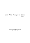
What’s Included
The ACB-232.LPCI is shipped with the following items. If any of these items are missing or damaged, contact the
supplier.
•
•
•
ACB-232.LPCI Adapter
Sealevel Software
Standard PCI Profile Bracket
Installation
Operation System Installation
Note: For the5103 to work properly in Windows 2000, Plug and Play OS must be turned off in the BIOS.
Choose Install Software at the beginning of the CD and select Install SeaMAC.
System Installation
The ACB-232.LPCI can be installed in any of the PCI expansion slots.
1. Turn off PC power. Disconnect the power cord.
2. Remove the PC case cover.
3. Locate an available PCI slot and remove the blank metal slot cover.
4. Gently insert the ACB-232.LPCI into the slot. Make sure the adapter is seated properly.
5. Replace the screw.
6. Replace the cover.
7. Connect the power cord.
Installation is complete.
Technical Description
Technical Description
The ACB-232.LPCI utilizes the Zilog 85230 Enhanced Serial Communications Controller (ESCC). This chip
features programmable baud rate, data format and interrupt control. Refer to the ESCC Users Manual for details on
programming the 85230 ESCC chip.
Features
•
One channel of synchronous or asynchronous communications using the Zilog Z85230 chip
•
EIA/TIA-232 Signals supported TD, RD, CTS, RTS, DCD, DSR, DTR, TXC, RXC, TSET, RI
•
Programmable options for Transmit clock as input or output
•
Software programmable baud rate
Internal Baud Rate Generator
The baud rate of the ESCC is programmed under software control. The standard oscillator supplied with the board is
7.3728 MHz. However, other oscillator values can be substituted to achieve different baud rates.
I/O Registers Definition - Control and Status
The control and status registers occupy 16 consecutive locations. The following tables provide a functional
description of the bit positions.
X = do not care
{ }= always this value
Address
Mode
D7
D6
D5
D4
D3
D2
D1
D0
Base+4
Base+4
Base+5
Base+5
Base+6
Base+6
Base+14
Base+15
RD
WR
RD
WR
RD
WR
RD
RD
{0}
X
{0}
X
{0}
X
SD7
SD15
IRQST
X
{0}
X
{0}
X
SD6
SD14
{0}
X
SYNCA_RTS
SYNCA_RTS
{0}
X
SD5
SD13
{0}
X
SYNCA_CTS
SYNCA_CTS
TXOUT
TXOUT
SD4
SD12
{0}
X
{0}
X
RIOUT
RIOUT
SD3
SD11
{0}
X
{0}
X
DSROUT
DSROUT
SD2
SD10
{0}
X
{0}
X
TSETSLA
TSETSLA
SD1
SD9
{0}
X
{0}
X
RXCOPTA
RXCOPTA
SD0
SD8
Field
IRQST
SYNCA_RTS
SYNCA_CTS
TSETSLA
RXCOPTA
DSROUT
RIOUT
TXOUT
SD0-SD15
Description
Base +4
SCC interrupt status: 1 = No interrupt pending on IUSC; 0 = Interrupt pending on IUSC.
Base +5
SYNCA _RTS – 0 = SYNCA is high, 1 = SYNCA connected to RTS ( 0 on power up )
SYNCA_CTS – 0 = SYNCA is high, 1 = SYNCA connected to CTS ( 0 on power up )
Base +6
CHAN A – TSET clock source 0 = TRXCA as source,
1= received TXC as source ( 0 on power up )
RXCOPTA – 0 = selects received RXC for RTXCA,
1 = selects SCC PCLK for RTXCA ( 0 on power up )
DSROUT – 0 = DSR not routed to SCC
1 = DSR routed to SCC DCDB (0 on power up)*
RIOUT – 0 = RI not routed to SCC
1 = RI routed to SCC CTSB (0 on power up)**
TXOUT – 0 = TXD routed from SCC to 1488
1 = Forces TXD always a high (for idle mark bug in ESCC)***
Base +14 and 15
Optional security feature. Unique value per customer or application. ( default value = FFFF)
* DSR- is connected to Port B DCD on the 85230 only when this bit is set to a 1. If 9015 compatibility is
required, this bit must be set as part of the SCC initialization.
** RI- is connected to Port B CTS on the 85230 only when this bit is set to a 1. If 9015 compatibility is required,
this bit must be set as part of the SCC initialization.
Sealevel Systems ACB-MP.PCI
Page 4
Technical Description
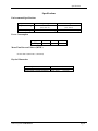
25 Pin Connector Signal Layouts (DB-25 Male)
RS-232 Signals
Signal
GND
RD
CTS
DSR
DCD
TXC
RXC
RI
TSET
DTR
TD
RTS
Name
Ground
Receive Data
Clear To Send
Data Set Ready
Data Carrier Detect
Transmit Clock
Receive Clock
Ring Indicator
Transmit Signal Element Timing
Data Terminal Ready
Transmit Data
Request To Send
Pin #
7
3
5
6
8
15
17
22
24
20
2
4
Mode
Input
Input
Input
Input
Input
Input
Input
Output
Output
Output
Output
RI- is connected to Port B CTS on the 85230 and the enable bit is set in Base+6.
DSR- is connected to Port B DCD on the 85230 the enable bit is set in Base+6.
Technical Note: Please terminate any control signals that are not going to be used. The most common way to do this
is connect RTS to CTS and RI. Also, connect DCD to DTR and DSR. Terminating these pins, if not used, will help
insure you get the best performance from your adapter.
Sealevel Systems ACB-MP.PCI
Page 5
Specifications
Specifications
Environmental Specifications
Specification
Temperature Range
Humidity Range
Operating
0 to 50 º C
(32 to 122 º F)
10 - 90% R.H. Non Condensing
Storage
-20 to 70 º C
(-4 to 158 ºF)
10 - 90% R.H. Non Condensing
Power Consumption
Supply line
Rating
+12VDC
50mA
-12VDC
50mA
+5 VDC
350 mA
Mean Time Between Failures (MTBF)
Greater than 150,000 hours. (Calculated)
Physical Dimensions
Board length
Board Height including Goldfingers
Board Height excluding Goldfingers
Sealevel Systems ACB-MP.PCI
4.721 inches
2.536 inches
2.211 inches
(11.99 cm)
(6.44 cm)
(5.62 cm)
Page 6
Appendix A - Troubleshooting
Appendix A - Troubleshooting
The Sealevel Software is supplied with the Sealevel Systems adapter and will be used in the troubleshooting
procedures. Using this software and following these simple steps can eliminate most common problems without the
need to call Technical Support.
1.
Identify all I/O adapters currently installed in your system. This includes the on-board serial ports, controller
cards, sound cards etc. The I/O addresses used by these adapters, as well as the IRQ (if any) should be
identified.
2.
Make sure the Sealevel Systems adapter is securely installed in a PCI slot.
3.
Use the supplied software and User Manual to verify that the Sealevel Systems adapter is configured correctly.
4.
Windows users can use the installed programs in the SeaMAC folder to verify operation.
Sealevel Systems ACB-MP.PCI
Page 7
Appendix B - How To Get Assistance
Appendix B - How To Get Assistance
Please refer to Troubleshooting Guide prior to calling Technical Support.
1.
Begin by reading through the Trouble Shooting Guide in Appendix A. If assistance is still needed
please see below.
2.
When calling for technical assistance, please have your user manual and current adapter settings. If
possible, please have the adapter installed in a computer ready to run diagnostics.
3.
Sealevel Systems provides an FAQ section on its web site. Please refer to this to answer many
common questions. This section can be found at http://www.sealevel.com/faq.htm .
4.
Sealevel Systems maintains a Home page on the Internet. Our home page address is
www.sealevel.com. The latest software updates, and newest manuals are available via our FTP site
that can be accessed from our home page.
5.
Technical support is available Monday to Friday from 8:00 a.m. to 5:00 p.m. eastern time. Technical
support can be reached at (864) 843-4343.
RETURN AUTHORIZATION MUST BE OBTAINED FROM SEALEVEL SYSTEMS BEFORE
RETURNED MERCHANDISE WILL BE ACCEPTED. AUTHORIZATION CAN BE OBTAINED BY
CALLING
SEALEVEL
SYSTEMS
AND
REQUESTING
A
RETURN
MERCHANDISE
AUTHORIZATION (RMA) NUMBER.
Sealevel Systems ACB-MP.PCI
Page 8
Appendix C - Electrical Interface
Appendix C - Electrical Interface
RS-232 Or EIA/TIA-232
Quite possibly the most widely used communication standard is RS-232. This implementation has been defined and
revised several times and is often referred to as RS-232 or EIA/TIA-232. It is defined by the EIA as the Interface
between Data Terminal Equipment and Data Circuit- Terminating Equipment Employing Serial Binary Data
Interchange. The mechanical implementation of RS-232 is on a 25-pin D sub connector. RS-232 is capable of
operating at data rates up to 20 Kbps at distances less than 50 ft. The absolute maximum data rate may vary due to
line conditions and cable lengths. RS-232 often operates at 38.4 Kbps over very short distances. The voltage levels
defined by RS-232 range from -12 to +12 volts. RS-232 is a single ended or unbalanced interface, meaning that a
single electrical signal is compared to a common signal (ground) to determine binary logic states. A voltage of +12
volts (usually +3 to +10 volts) represents a binary 0 (space) and -12 volts (-3 to -10 volts) denotes a binary 1 (mark).
The RS-232 and the EIA/TIA-574 specification defines two type of interface circuits, Data Terminal Equipment
(DTE) and Data Circuit-Terminating Equipment (DCE). The Sealevel Systems adapter is a DTE interface.
Sealevel Systems ACB-MP.PCI
Page 9
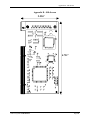
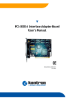
Appendix D - Silk-Screen
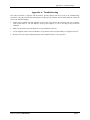
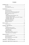
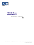
Appendix D - Silk-Screen
2.536"
4.721"
Sealevel Systems ACB-MP.PCI
Page 10
Appendix E – Compliance Notices
Appendix E - Compliance Notices
Federal Communications Commission Statement
FCC - This equipment has been tested and found to comply with the limits for Class A digital device, pursuant to
Part 15 of the FCC Rules. These limits are designed to provide reasonable protection against harmful interference
when the equipment is operated in a commercial environment. This equipment generates, uses, and can radiate radio
frequency energy and, if not installed and used in accordance with the instruction manual, may cause harmful
interference to radio communications. Operation of this equipment in a residential area is likely to cause harmful
interference in such case the user will be required to correct the interference at his own expense.
EMC Directive Statement
Products bearing the CE Label fulfill the requirements of the EMC directive (89/336/EEC) and of
the low-voltage directive (73/23/EEC) issued by the European Commission.
To obey these directives, the following European standards must be met:
•
EN55022 Class A - “Limits and methods of measurement of radio interference characteristics of
information technology equipment”
•
EN55024 -'Information technology equipment Immunity characteristics Limits and methods of
measurement'
•
EN60950 (IEC950) - “Safety of information technology equipment, including electrical business
equipment”
Warning
This is a Class A Product. In a domestic environment this product may cause radio interference in which case
the user may be required to take adequate measures.
Always use cabling provided with this product if possible. If no cable is provided or if an alternate cable is required,
use high quality shielded cabling to maintain compliance with FCC/EMC directives.
Sealevel Systems ACB-MP.PCI
Page 11
Warranty
Warranty
Sealevel Systems, Inc. provides a limited lifetime warranty. Should this product fail to be
in good working order at any time during this period, Sealevel Systems will, at it’s option,
replace or repair it at no additional charge except as set forth in the following terms. This
warranty does not apply to products damaged by misuse, modifications, accident or
disaster.
Sealevel Systems assumes no liability for any damages, lost profits, lost savings or any other incidental or
consequential damage resulting from the use, misuse of, or inability to use this product. Sealevel Systems will not
be liable for any claim made by any other related party.
RETURN AUTHORIZATION MUST BE OBTAINED FROM SEALEVEL SYSTEMS BEFORE
RETURNED MERCHANDISE WILL BE ACCEPTED. AUTHORIZATION CAN BE OBTAINED BY
CALLING
SEALEVEL
SYSTEMS
AND
REQUESTING
A
RETURN
MERCHANDISE
AUTHORIZATION (RMA) NUMBER.
Sealevel Systems, Incorporated
155 Technology Place
P.O. Box 830
Liberty, SC 29657 USA
(864) 843-4343 FAX:(864) 843-3067
www.sealevel.com
email: [email protected]
Technical Support is available from 8 a.m. to 5 p.m. Eastern time.
Monday - Friday
Trademarks
Sealevel Systems, Incorporated acknowledges that all trademarks referenced in this manual are the service mark,
trademark, or registered trademark of the respective company.
ACB-232.LPCI is a trademark of Sealevel Systems, Incorporated.
Sealevel Systems ACB-MP.PCI
Page 12