1
PCI-DIO16 Interface Adapter Board
User’s Manual
Manual PN: 931-0005-00-A
June 2000
Customer Service
Mailing Address:
Kontron - United States
14118 Stowe Drive
Poway, CA 92064 USA
Tel: 858-677-0877
Fax: 858-677-0895
Technical Support:
U.S. and Canadian Customers - 24 hours a day
Tel: 800-480-0044, option 1
Fax: 858-677-0898
International Customers - 9am to 4pm local time
Tel: (+49) 8165-77 112
Fax: (+49) 8165-77 110
Visit our site at:
www.kontron.com
© 2005 Kontron, an International Corporation. All rights reserved.
The information in this user’s guide is provided for reference only. Kontron does not assume
any liability arising out of the application or use of the information or products described
herein. This user’s guide may contain or reference information and products protected by
copyrights or patents and does not convey any license under the patent rights of Kontron, nor
the rights of others.
Kontron is a registered trademark of Kontron. All trademarks, registered trademarks, and
trade names used in this user’s guide are the property of their respective owners. All rights
reserved. Printed in the United States of America and Canada. This user’s guide contains
information proprietary to Kontron. Customers may reprint and use this user’s guide in other
publications. Customers may alter this user’s guide and publish it only after they remove the
Kontron name, cover, and logo.
Kontron reserves the right to make changes without notice in product or component design as
warranted by evolution in user needs or progress in engineering or manufacturing technology.
Changes which affect the operation of the unit will be documented in the next revision of this
user’s guide.
³
Safety Instructions
Contents
Before You Begin . . . . . . . . . . . . . . . . . . . . . . . . . . . . . . . . . . . . . . . . . . . . iii
When Working Inside a Computer . . . . . . . . . . . . . . . . . . . . . . . . . . . . . . . . iv
Preventing Electrostatic Discharge . . . . . . . . . . . . . . . . . . . . . . . . . . . . . . v
This page intentionally left blank.
ii
User’s Guide
Before You Begin
Before handling the product, read the instructions and safety guidelines on the following pages
to prevent damage to the product and to ensure your own personal safety. Refer to the
“Advisories” section in the Preface for advisory conventions used in this user’s guide, including
the distinction between Warnings, Cautions, Important Notes, and Notes.
Always use caution when handling/operating the computer. Only qualified,
experienced, authorized electronics service personnel should access the interior
of the computer. The power supplies produce high voltages and energy hazards,
which can cause bodily harm.
Use extreme caution when installing or removing components. Refer to the
installation instructions in this user’s guide for precautions and procedures. If you
have any questions, please contact Kontron Post-Sales Technical Support.
WARNING
High voltages are present inside the chassis when the unit’s power
cord is plugged into an electrical outlet. Turn off system power, turn
off the power supply, and then disconnect the power cord from its
source before removing the chassis cover. Turning off the system
power switch does not remove power to components.
B
User’s Guide
Before You Begin iii
Safety Instructions
³
³
When Working Inside a Computer
Before taking covers off a computer, perform the following steps:
1) Turn off the computer and any peripherals.
2) Disconnect the computer and peripherals from their power sources or subsystems to
prevent electric shock or system board damage. This does not apply when hot swapping
parts.
3) Follow the guidelines provided in “Preventing Electrostatic Discharge” on the following
page.
4) Disconnect any telephone or telecommunications lines from the computer.
In addition, take note of these safety guidelines when appropriate:
To help avoid possible damage to system boards, wait five seconds after turning
off the computer before removing a component, removing a system board, or
disconnecting a peripheral device from the computer.
When you disconnect a cable, pull on its connector or on its strain-relief loop, not
on the cable itself. Some cables have a connector with locking tabs. If you are
disconnecting this type of cable, press in on the locking tabs before disconnecting
the cable. As you pull connectors apart, keep them evenly aligned to avoid
bending any connector pins. Also, before connecting a cable, make sure both
connectors are correctly oriented and aligned.
CAUTION
Do not attempt to service the system yourself except as explained in
this user’s guide. Follow installation and troubleshooting
instructions closely.
iv
User’s Guide
Preventing Electrostatic Discharge
Safety Instructions
³
Static electricity can harm system boards. Perform service at an ESD workstation and follow
proper ESD procedure to reduce the risk of damage to components. Kontron strongly encourages
you to follow proper ESD procedure, which can include wrist straps and smocks, when servicing
equipment.
You can also take the following steps to prevent damage from electrostatic discharge (ESD):
When unpacking a static-sensitive component from its shipping carton, do not
remove the component’s antistatic packing material until you are ready to install
the component in a computer. Just before unwrapping the antistatic packaging,
be sure you are at an ESD workstation or grounded. This willl discharge any static
electricity that may have built up in your body.
When transporting a sensitive component, first place it in an antistatic container
or packaging.
Handle all sensitive components at an ESD workstation. If possible, use antistatic
floor pads and workbench pads.
Handle components and boards with care. Don’t touch the components or contacts
on a board. Hold a board by its edges or by its metal mounting bracket.
Do not handle or store system boards near strong electrostatic, electromagnetic,
magnetic, or radioactive fields.
Preventing Electrostatic Discharge
User’s Guide
Preventing Electrostatic Discharge
v
This page intentionally left blank.
vi
User’s Guide
³
Preface
Contents
Customer Comments. . . . . . . . . . . . . . . . . . . . . . . . . . . . . . . . . . . . . . . . . . iii
Advisory Conventions. . . . . . . . . . . . . . . . . . . . . . . . . . . . . . . . . . . . . . . . . iv
Unpacking . . . . . . . . . . . . . . . . . . . . . . . . . . . . . . . . . . . . . . . . . . . . . . . . . v
Regulatory Compliance Statements . . . . . . . . . . . . . . . . . . . . . . . . . . . . . . vi
Guarantee and Warranty Policy . . . . . . . . . . . . . . . . . . . . . . . . . . . . . . viii-xi
This page intentionally left blank.
ii
User’s Guide
³
Customer Comments
If you have any difficulties using this user’s guide, discover an error, or just want to provide some
feedback, please send us a message using the online form under “Contact Us” on our web site
(www.kontron.com) under “Technical Support.” Detail any errors you find. We will correct the
errors or problems as soon as possible and post the revised user’s guide in our online Support
Library. Thank you.
Preface
Note: You may also use the online form on our web site to submit comments or
concerns about our products, or request technical support.
User’s Guide
iii
³
Advisory Conventions
Four types of advisories are used throughout the user guides to provide helpful information or to
alert you to the potential for hardware damage or personal injury. They are Notes, Cautions, and
Warnings. The following is an example of each type of advisory. Use caution when servicing
electrical components.
Note: A note is used to make helpful information stand out.
.
Important: An important note indicates information that is important for you to
know.
CAUTION
A CAUTION indicates potential damage to hardware and tells you how
to avoid the problem.
WARNING
A WARNING indicates the potential for bodily harm and tells you how
to avoid the problem.
Disclaimer: We have tried to identify all situations that may pose a warning or caution condition
in this user’s guide. However, Kontron does not claim to have covered all situations that might
require the use of a Caution or Warning.
iv
User’s Guide
³
Unpacking
When unpacking, follow these steps:
1) After opening the box, save it and the packing material for possible future shipment.
2) Remove all items from the box. If any items listed on the purchase order are missing,
notify Kontron customer service immediately.
Preface
3) Inspect the product for damage. If there is damage, notify Kontron customer service
immediately. Refer to “Guarantee and Warranty Policy” for the return procedure.
User’s Guide
Unpacking
v
³
Regulatory Compliance Statements
This section provides the FCC compliance statement for Class A devices and describes how to keep
the system CE compliant.
³
FCC Compliance Statement for Class A Devices
The product(s) described in this user’s guide has been tested and found to comply with the limits
for a Class A digital device, pursuant to Part 15 of the FCC Rules. These limits are designed to
provide reasonable protection against harmful interference when the equipment is operated in a
commercial environment. This equipment generates, uses, and can radiate radio frequency
energy and, if not installed and used in accordance with the user’s guide, may cause harmful
interference to radio communications. Operation of this equipment in a residential area
(domestic environment) is likely to cause harmful interference, in which case the user will be
required to correct the interference (take adequate measures) at their own expense.
Changes or modifications not expressly approved by Kontron could void the user's authority to
operate the equipment.
Note: The assembler of a personal computer system may be required to test the
system and/or make necessary modifications if a system is found to cause harmful
interference or to be noncompliant with the appropriate standards for its intended
use.
³
CE Certification
The product(s) described in this user’s guide complies with all applicable European
Union (CE) directives if it has a CE marking. The CE declaration of conformity is
provided on the last page of this user’s guide. For computer systems to remain CE
compliant, only CE-compliant parts may be used. Maintaining CE compliance also requires proper
cable and cabling techniques. Although Kontron offers accessories, the customer must ensure
that these products are installed with proper shielding to maintain CE compliance. Kontron does
not offer engineering services for designing cabling systems. In addition, Kontron will not retest
or recertify systems or components that have been reconfigured by customers.
vi
User’s Guide
Preface
This page intentionally left blank.
User’s Guide
Regulatory Compliance Statements
vii
³
³
Guarantee and Warranty Policy
Guarantee
A thirty day money-back guarantee is provided on all standard products sold. Special order
products are covered by our Limited Warranty, however they may not be returned for refund or
credit. EPROMs, RAM, Flash EPROMs or other forms of solid electronic media are not returnable for
credit - but for replacement only. An extended warranty is available. Consult the factory.
³
Refunds
In order to receive a refund on a product for the purchase price, the product must not have been
damaged by the customer or by the common carrier chosen by the customer to return the goods
and the product must be returned complete (meaning all user’s guides, software, cables, etc.)
within 30 days of receipt and in an as-new and resalable condition. The “Return Procedure” must
be followed to assure a prompt refund.
³
Restocking Charges
Product returned after 30 days, and before 60 days, of the purchase will be subject to a minimum
20% restocking charge and charges for any damaged or missing parts. Products not returned
within 60 days of purchase, or products which are not in an as-new and resalable condition, are
not eligible for a credit return and will be returned to the customer.
³
Limited Warranty
Effective April 1, 1998, all products carry a 2-year limited warranty. Within 2 years of purchase,
Kontron will repair or replace, at our option, any defective product. Kontron will service the
warranty for all standard catalog products for the first two years from the date of shipment.
Please note: The 2-year warranty may not apply to special promotion items. Please consult the
factory for warranty verification.
viii
User’s Guide
The limited warranty is void if the product has been subjected to alteration, neglect, misuse, or
abuse; if any repairs have been attempted by anyone other than Kontron or its authorized agent;
or if the failure is caused by accident, acts of God, or other causes beyond the control of Kontron
or the manufacturer. Neglect, misuse, and abuse shall include any installation, operation, or
maintenance of the product other than in accordance with the user’s guide.
³
Preface
No agent, dealer, distributor, service company, or other party is authorized to change, modify, or
extend the terms of this Limited Warranty in any manner whatsoever. Kontron reserves the right
to make changes or improvements in any product without incurring any obligation to similarly
alter products previously purchased.
Return Procedure
For any Guarantee or Limited Warranty return, please contact Kontron Customer Service at 800480-0044 or 858-677-0877 and obtain a Return Material Authorization (RMA) Number. All
product(s) returned to Kontron for service or credit must be accompanied by a Return Material
Authorization (RMA) Number. Freight on all returned items must be prepaid by the customer who
is responsible for any loss or damage caused by common carrier in transit. Returns for Warranty
must include a Failure Report for each unit, by serial number(s), as well as a copy of the original
invoice showing the date of purchase.
To reduce risk of damage, returns of product must be in an Kontron shipping container. If the
original container has been lost or damaged, new shipping containers may be obtained from
Kontron Customer Service at a nominal cost.
Kontron owns all parts removed from repaired products. Kontron uses new and reconditioned
parts made by various manufacturers in performing warranty repairs and building replacement
products. If Kontron repairs or replaces a product, its warranty term is not extended.
Kontron will normally return your replacement or repaired items via ground. Overnight delivery
or delivery via other carriers is available at an additional charge.
Shipments not in compliance with this Guarantee and Limited Warranty Return Policy will not be
accepted by Kontron.
User’s Guide
Guarantee and Warranty Policy
ix
³
Limitation of Liability
In no event shall Kontron be liable for any defect in hardware, software, loss, or inadequacy of
data of any kind, or for any direct, indirect, incidental, or consequential damages in connection
with or arising out of the performance or use of any product furnished hereunder. Kontron’s
liability shall in no event exceed the purchase price of the product purchased hereunder. The
foregoing limitation of liability shall be equally applicable to any service provided by Kontron or
its authorized agent.
Some sales items and customized systems are not subject to the guarantee and limited warranty.
However in these instances, any deviations will be disclosed prior to sales and noted in the
original invoice. Kontron reserves the right to refuse returns or credits on software or special
order items.
x
User’s Guide
Preface
This page intentionally left blank.
User’s Guide
Guarantee and Warranty Policy
xi
Contents
Chapter 1
Introduction
Overview . . . . . . . . . . . . . . . . . . . . . . . . . . . . . . . . . . . . . . . . . . . . . . . . . . 1-1
What’s Included . . . . . . . . . . . . . . . . . . . . . . . . . . . . . . . . . . . . . . . . . . . . . 1-1
Chapter 2
Installation
Board Setup . . . . . . . . . . . . . . . . . . . . . . . . . . . . . . . . . . . . . . . . . . . . . . . .
Software Installation. . . . . . . . . . . . . . . . . . . . . . . . . . . . . . . . . . . . . . . . .
For Windows 98/2000/NT Users. . . . . . . . . . . . . . . . . . . . . . . . . . . . .
System Installation . . . . . . . . . . . . . . . . . . . . . . . . . . . . . . . . . . . . . . . . . .
2-1
2-1
2-1
2-1
Chapter 3
Technical Description
Features . . . . . . . . . . . . . . . . . . . . . . . . . . . . . . . . . . . . . . . . . . . . . . . . . . .
Port A: Input port . . . . . . . . . . . . . . . . . . . . . . . . . . . . . . . . . . . . . . . . . . .
Port C: Output Port (Reed Relay) . . . . . . . . . . . . . . . . . . . . . . . . . . . . . . .
Relay Specifications . . . . . . . . . . . . . . . . . . . . . . . . . . . . . . . . . . . . . .
Software . . . . . . . . . . . . . . . . . . . . . . . . . . . . . . . . . . . . . . . . . . . . . . . . . . .
Programming Examples . . . . . . . . . . . . . . . . . . . . . . . . . . . . . . . . . . .
3-1
3-1
3-3
3-3
3-4
3-5
Chapter 4
Specifications
Appendix A
Troubleshooting
Appendix B
Board Layout Drawing
Tables
Table 3-1. Sensor Input Port Pin Assignments (P3 DB-37 Male) . . . . . . 3-3
Table 3-2. Output Port (Reed Relay) Pin Assignments (P3 DB-37 Male)3-4
Table 3-3. Power and Ground Pin Assignments (P3 DB-37 Male) . . . . . 3-4
Table 3-4. Register Description. . . . . . . . . . . . . . . . . . . . . . . . . . . . . . . . . 3-5
Contents
xv
This page intentionally left blank.
xvi
PCI-DIO16 User’s Guide
Chapter 1
Introduction
Overview
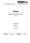
ThePCI-DIO16 interface adapter board provides:
�
Eight reed relays, which can latch power, data, or other electronic
signals for control applications
�
Eight optically isolated inputs, to allow monitoring of off-board switch
closures or relays, or for general purpose monitoring needs
The PCI-DIO16 is PC compatible and PCI slot.
What’s Included
The PCI-DIO16 board is shipped with the following items. If any of these
items are missing or damaged, contact ICS Advent.
�
PCI-DIO16 interface adapter board
�
Software drivers
�
User’s Guide
Introduction
1-1
This page intentionally left blank.
Chapter 2
Installation
Board Setup
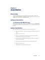
The PCI-DIO16 board is a fully compliant PCI “Plug-n-Play” adapter. All
board resources (I/O address and IRQ) are autoassigned by either your system
BIOS or your “Plug-n-Play” operating system.
Software Installation
For Windows 98/2000/NT Users
Run setup from floppy disk 1. Then, install SeaI/O and select the Digital I/O
software drivers. For users of DOS, Windows 3.1, etc., run disk 3 and the Read
Me file.
System Installation
The PCI-DIO16 board can be installed in any PCI expansion slot.
1) Turn off system power. Disconnect the power cord from the electrical
outlet.
2) Remove the chassis cover.
3) Locate an available PCI slot and remove the associated slot filler
bracket from the rear panel of the chassis.
4) Gently insert the PCI-DIO16 into the PCI slot. Make sure that the
board is seated properly.
5) Secure the board’s slot bracket to the rear panel with a screw.
6) Replace the chassis cover.
7) Plug the power cord into an electrical outlet.
Installation
2-1
This page intentionally left blank.
2-2 PCI-DIO16 User’s Guide
Chapter 3
Technical Description
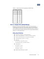
The PCI-DIO16 interface adapter board provides two parallel input/output
(I/O) ports. The ports are organized as ports A, B, C, and D. Ports A and C are
the only ports used. This is done to maintain compatibility with software
written for the PCI-DIO32 board, which has twice as much I/O, and hence,
uses more ports. Port A is an input port interfaced to optically isolated inputs.
Port C is the reed relay output port.
Features
�
Eight SPST relays
�
One 8-bit optically isolated input port
�
DB-37 male connector for relay outputs
�
Highly reliable 10VA DIP reed relays
�
Multiple adapters residing in one computer
�
PCI 2.1 bus compatibility
Port A: Input port
Port A is an eight-bit input port connected to optically isolated input sensors.
Each sensor can be used to interface a voltage input and then sense whether
the voltage is on or off. Each sensor is isolated from every other sensor with
respect to a common ground, and each is isolated with respect to the host PC
ground. This means that signals such as low level AC line voltage, motor servo
voltage, and control relay signals can be sensed, or read, by the PC without the
risk of damage due to ground loops or ground faults.
Each sensor input pair has a current limiting resistor that is used to limit the
input current to the opto-isolator. The opto-isolator has two “back-to-back”
internal diodes. This allows AC or DC signals to be sensed, regardless of
polarity. When the applied voltage is high enough to cause the LED in the
opto-isolator to turn on, the output of the opto-isolator goes low (0 volts) and
the signal is read as a low logic level (binary 0) by the PC. When the input
signal is too low to turn on the opto-isolator, the output goes high and the port
bit is read by the PC as a high logic level (binary 1).
Technical Description
3-1
The input impedance of each isolated input is approximately 560 ohms
(factory default). The opto-isolator requires approximately 3 mA to turn on.
The maximum input current is 60 mA. There are two things to consider when
selecting the input resistor: (1) the turn-on voltage, sensed by the circuit; and
(2) the maximum input voltage. The maximum input voltage must not provide
too much power to the input resistor, and it also must not overdrive the
opto-isolator input current specification. The following formulas apply:
�
Turn-on current = 3 mA
�
Isolator diode drop = 1.1V
�
Maximum resistor power = 0.25W
Turn-on voltage = diode drop + (turn on current) x (resistance)
Or:
1.1 + (0.003) x R
Maximum voltage = square root of (0.25 x (resistor value))
The following table shows four common input resistors and the ranges
associated with each:
Input
Resistor
(ohms)
Value
Turn-On
Max Input
Voltage
Max
Current
(volts)
(volts)
(mA)
220
1.76
7
27
560*
2.80
12
20
1K
4.10
16
15
2.2K
7.70
24
10
*Factory default
Increasing the input resistor accordingly can increase the maximum input
voltage. Because socketed DIP resistor networks are used, they can easily be
replaced with a different value. This can be done at the factory. The input
circuits are not intended for monitoring 120-volt AC circuits. This
voltage is too high for the circuits and dangerous to have on the board.
3-2
PCI-DIO16 User’s Guide
Table 3-1. Sensor Input Port Pin Assignments (P3 DB-37 Male)
Port A Bit
P3 Pin#
0
2,20
1
3,21
2
4,22
3
5,23
4
6,24
5
7,25
6
8,26
7
9,27
Port C: Output Port (Reed Relay)
Reed relays provide very high quality, long life, low current (ten watts
maximum), dry-contact switch closures. Reed relays are not suited for high
current applications. They can be destroyed by inductive load switching,
where a spark occurs across the contacts internally. The relays are normally
open, and close when energized. Each relay can be energized individually by
writing a “1” to the proper port bit.
Relay Specifications
�
Contact Power Ratings = 10 watts maximum
�
Contact Voltage Maximum = 100VDC or 100VAC maximum
�
Contact Current Maximum = 0.5 amps DC or AC RMS
�
Contact Resistance, Initial = 0.15 ohms
�
Rated Life:
�
�
J
Low Load = 200 million closures
J
Maximum Load = 100 million closures
Contact Speed:
J
Operate = 0.5 ms
J
Release = 0.5 ms
J
Bounce = 0.5 ms
Maximum Operating Speed = 600Hz
Technical Description
3-3
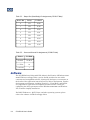
Table 3-2. Output Port (Reed Relay) Pin Assignments (P3 DB-37 Male)
Port C Bit
Relay
P3 Pin#
0
K1
10,28
1
K2
11,29
2
K3
12,30
3
K4
13,31
4
K5
14,32
5
K6
15,33
6
K7
16,34
7
K8
17,35
Table 3-3. Power and Ground Pin Assignments (P3 DB-37 Male)
Power
P3 Pin#
Ground
18,36,37
+ 5 Volts
19
+ 12 Volts
1
Software
The PCI-DIO16 board ships with ICS Advent’s SeaI/O suite of Windows 95/98/
2000/NT drivers on floppy disks 1 and 2. SeaI/O provides the user with a
consistent and straightforward API, allowing the developer to concentrate on
the details of the application instead of low level driver development. Popular
development environments, including Visual C++, Visual Basic, and Delphi,
are supported for application development. SeaI/O includes a utility for
configuring the driver parameters under Windows 95/98/2000 and Windows
NT, to further simplify installation.
For DOS, Windows 3.1, QNX, Linux, and other operating systems, please
refer to the software included on floppy disk 3.
3-4
PCI-DIO16 User’s Guide
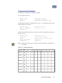
Programming Examples
All examples assume a base address of 300 hex.
To read inputs at Port A:
MOV DX, 300H
IN AL, DX
NOT AL
;Set DX to Port A
;Get Input Port Data
;Data read is negative logic
Programming example to set Relay #3 on, write a ‘1’ in bit position D3, to port
address Base+3, or 303 hex.
MOV DX, 303H
MOV AL, 00001000B
OUT DX, AL
;Set DX to Port D
;Set bit 3 to a ‘1’
Another method that takes into account the read-back capability of the output
ports C and D:
MOV DX, 303H
IN AL, DX
NOT AL
OR AL, 00001000B
OUT DX, AL
;Set DX to Port D
;Get old port setting
;Invert bits – see note below
;OR in bit 3
;Set bit 3
Note: Reading back the ports (C and D) results in the binary complement of
the output.
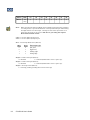
Table 3-4. Register Description
Address
Mode
D7
D6
D5
D4
D3
D2
D1
D0
Base+0
RD/
WR
PAD7
PAD6
PAD5
PAD4
PAD3
PAD2
PAD1
PAD0
Base+1
RD
Only
{0}
{0}
{0}
{0}
{0}
{0}
{0}
{0}
Base+2
RD/
WR
PCD7
PCD6
PCD5
PAD4
PCD3
PCD2
PCD1
PCD0
Base+3
RD
Only
{0}
{0}
{0}
{0}
{0}
{0}
{0}
{0}
Base+4
RD
Only
{0}
{0}
{0}
{0}
{0}
{0}
{0}
{0}
Base+5
RD/
WR
IRQEN
IRQST
{0}
{0}
{0}
{0}
IRC1
IRC0
Base+6
RD
Only
{0}
{0}
{0}
{0}
{0}
{0}
{0}
{0}
Technical Description
3-5
Address
Mode
D7
D6
D5
D4
D3
D2
D1
D0
Base+7
RD
Only
{0}
{0}
{0}
{0}
{0}
{0}
{0}
{0}
Note:
When selecting the Interrupt Mode, always disable interrupts before changing
or setting states, to prevent inadvertent or unexpected interrupts. When using
the high and low level interrupts, a change in state of the input must occur
before the interrupt can be cleared. The device providing the input to
Base+0 bit D0 must do this.
PAD0–7 = Port A (Base+0) Input port.
PCD0–7 = Port C (Base+2) Output port.
IRC0–1= Interrupt Mode select (Base+5):
IRC1
0
0
1
1
IRC0
0
1
0
1
Interrupt type
low level
high level
falling edge
rising edge
IRQEN = enable interrupts (Base+5)
0 = disabled
1 = enabled (disabled after reset or power up).
IRQEN = enable interrupts (Base+5)
0 = disabled
1 = enabled (disabled after reset or power up).
IRQST = interrupt status (Base+5)
1 = interrupt pending (reading the bit clears interrupt)
3-6
PCI-DIO16 User’s Guide
Chapter 4
Specifications
Power Requirements
+5VDC
Size
Length: 5.00 in (127mm)
Height: 3.90 in (99mm) with goldfingers,
3.58 in (91 mm) excluding goldfingers
Weight
3.2 ounces (90.71 g)
Temperature Range
Operating: 0 °C to 50 °C (32 °F to 122 °F)
Storage: -20 °C to 70 °C (-4 °F to 158 °F)
Humidity
10 to 90% RHNC
MTBF
Greater than 150,000 hours (calculated)
Agency Approvals
FCC Class A (47 CFR Part 15, Subpart B)
UL 1950, 2nd edition 1993
CE Conformity with:
EU EMC Directive 89/336/EEC
EU Low Voltage Directive 72/23/EEC
Specifications
4-1
This page intentionally left blank.
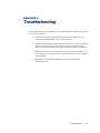
Appendix A
Troubleshooting
The following steps can eliminate most common problems without the need to
call technical support.
1) Install the software first, then add the hardware. This places the
required installation files in the correct locations.
2) Identify all I/O adapters currently installed in your system, including
onboard serial ports, controller cards, and sound cards. The I/O
addresses and any IRQs used by these adapters should be identified.
3) Ensure that there is no conflict with currently installed adapters. No
two adapters can occupy the same I/O address and may not be allowed
to share IRQs.
4) Make sure the PCI-DIO16 adapter is securely installed in a
motherboard slot.
Troubleshooting
A-1
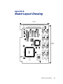
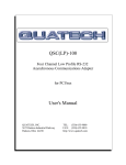
Appendix B
Board Layout Drawing
3.90"
5.00"
Board Layout Drawing
B-1
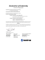
Declaration of Conformity
Information Technology Equipment
The product(s) covered by this declaration has a CE marking:
PCI-DIO16 Interface Adapter Board
The European Union directives covered by this declaration:
EMC Directive 89/336/EEC and Low Voltage Directive 73/23/EEC
The basis on which conformity is declared:
EN 50081-1:1992 Emissions, Generic Requirements
-EN 55022:1998 Limits and Methods of Measurement of Radio Disturbance
Characteristics of Information Technology Equipment
EN 50082-1:1992 Immunity, Generic Requirements
- EN61000-4-2: 1995 Electrostatic Discharge (ESD) Immunity
- EN61000-4-3: 1995 Radiated RF Field Immunity
- EN61000-4-4: 1995 EFT Immunity for AC and I/O Lines
The technical documentation required to demonstrate this product meets the requirements of the EMC Directive and the Low
Voltage Directive has been compiled by Kontron and is available for inspection by the relevant enforcement authorities.
Attention
The attention of the specifier, purchaser, installer, or user is drawn to special measures and limitations for
use which must be observed when the product is taken into service to maintain compliance with the above
directives. Details of these special measures and limitations are in the product manual.
Mr. Thomas Sparrvik
President/CEO Kontron America
Kontron - United States
14118 Stowe Drive
Poway, CA 92064 USA
Tel: 858-677-0877
Fax: 858-677-0895
Kontron - Canada
616 Curé- Boivin
Boisbriand (Québec) Canada
J7G 2A7
Tel: 800-387-4222
Fax: 450-437-8053
Kontron - Europe, Middle East, and Africa
Oskar-von-Miller-Straße 1
85386 Eching/München, Germany
Tel: +49 81-65 77 0
Fax: +49 81-65 77 219