1
T24-AR
Active Repeater
User Manual
mantracourt.com
Introduction / Overview ........................................................................................................2
Increase Range ............................................................................................................... 2
Span Obstacles ............................................................................................................... 2
Combined Solutions ......................................................................................................... 3
Power Options ....................................................................................................................3
Permanently Powered ...................................................................................................... 3
Battery Powered ............................................................................................................. 3
Connecting Power ........................................................................................................... 3
Getting Started ...................................................................................................................4
Considerations ....................................................................................................................4
Configuration......................................................................................................................5
Installation ...................................................................................................................... 5
T24 Toolkit.................................................................................................................... 5
Base Station .................................................................................................................. 5
T24 Toolkit ...................................................................................................................... 6
General Pages ................................................................................................................ 6
Setup Base Station Communications .................................................................................. 6
Home ........................................................................................................................ 7
Analyser .................................................................................................................... 8
Information ................................................................................................................ 9
Channel and Encryption ............................................................................................... 10
Save and Restore........................................................................................................ 11
Battery and Radio Levels ................................................................................................. 12
Battery and Radio Levels Advanced Settings ......................................................................... 13
Settings ................................................................................................................... 14
Specifications ................................................................................................................... 15
General Radio ................................................................................................................. 15
T24-AR.......................................................................................................................... 15
Approvals ........................................................................................................................ 16
CE ............................................................................................................................... 16
FCC.............................................................................................................................. 16
Industry Canada .............................................................................................................. 17
OEM / Reseller Marking and Documentation Requirements .......................................................... 17
FCC.............................................................................................................................. 17
IC ................................................................................................................................ 17
CE ............................................................................................................................... 17
Declaration of Conformity ................................................................................................... 19
Worldwide Regional Approvals .............................................................................................. 20
Important Note ............................................................................................................ 20
Warranty ......................................................................................................................... 20
1
Mantracourt Electronics Limited T24-AR User Manual
Introduction / Overview
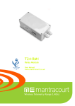
The T24-AR is an active repeater which will allow the T24 range of modules to span around obstacles or
increase range or coverage.
The connectivity module provides a battery holder for a pair of alkaline ‘D’ cells and has regulator circuitry for
an external power supply. The batteries can also be used to provide power in case of external supply failure.
The case is environmentally sealed to IP65.
The repeater will allow messages to be repeated once which can effectively double the radio range. Adding
more repeaters will not increase range but can increase coverage.
Increase Range
With No
Repeater
With Repeater
Span Obstacles
With No
Repeater
With Repeater
Mantracourt Electronics Limited T24-AR User Manual
2
Combined Solutions
Many
Consumers
Many
Providers
Power Options
The T24-AR can operate permanently powered or can operate from on-board batteries.
Permanently Powered
This is the simplest way to operate the repeater. With a permanent supply you do not need to worry about the
repeater sleeping or waking. You can optionally choose whether the repeater always wakes sleeping modules
and then you could utilise the powering up of the repeater to wakeup those modules outside the normal radio
range.
Battery Powered
In low power battery mode the repeater wakes from sleep when other modules are woken and will remain
awake until it stops receiving Stay Awake messages. This will work transparently with most T24
instrumentation. Please note that a T24-HS handheld would require radio firmware version 2.01 or above to be
able to wake a repeater when powered on.
You just need to decide on the Sleep Delay for a battery powered repeater. This causes the repeater to enter
sleep mode if it does not receive stay awake messages within the Sleep Delay time.
Stay awake messages are transmitted by handhelds, analog output modules and PC software etc so that when
those items are turned off or disabled all other T24 modules will sleep when their Sleep Delay time elapses.
Connecting Power
Power can be supplied by fitting 2 X ‘D’ cell alkaline 1.5 Volt batteries or the module can be supplied from an
external 5V to 18V DC source.
3
Mantracourt Electronics Limited T24-AR User Manual
In both cases you need to fit the JP1 power jumper to supply power to the acquisition module.
When powered from the external DC source the LED will illuminate.
If internal batteries are fitted when external power is applied the batteries will be utilized if external power is
lost.
Getting Started
Use the T24 Toolkit to ensure that the repeater radio channel matches the rest of the T24 modules. You will
then need to decide whether the repeater is battery powered or permanently externally powered and whether
it should always wake other sleeping modules when it is powered up and awake.
Considerations
•
Each repeater can effectively double the amount of traffic transmitted. Be careful not to introduce too
many repeaters that are within range of each other as there may be un-necessary duplication of radio
traffic. Carefully plan the layout of radio modules to minimise this.
Using the Data Provider monitor in the T24 Toolkit can show the amount of traffic. The T24 Toolkit on a
laptop or netbook is ideal for checking installations as it is mobile so traffic can be monitored at
different points in the installation.
•
A repeater will not repeat a packet that has already been repeated. Hence there is only one extra
‘hop’ introduced and a maximum range increase to 2X.
•
When waking remote modules separated by a repeater and that repeater is asleep it may take twice as
long to wake a module as when no repeater is involved.
•
If the repeater is to be battery powered use the same Sleep Delay as is suitable for the acquisition
modules in the system.
•
You cannot pair to a module through a repeater. Using the T24 Toolkit it may be possible to configure
module through a repeater by connecting without pairing. The results will vary depending on the
number of repeaters and amount of radio traffic. In some cases it may be necessary to power down
repeaters when configuring modules.
•
Most data consumer modules and software issue a broadcast wake when turned on or activated and this
will also wake a sleeping repeater which will then proceed to wake those modules within its range.
But some modules only wake specific single target modules such as the T24-HS handheld module and
the T24-AO1 analog output module. For these modules to wake the repeater they must be fitted with
at least v2.1 version radio modules. This only affects repeaters with a SleepDelay set.
Mantracourt Electronics Limited T24-AR User Manual
4
Configuration
This section explains how to install software and connect the required devices together. Please note that you
will need the T24 Toolkit software and a T24-BS base station to allow your computer to communicate with T24
telemetry devices.
Installation
T24 Toolkit
To configure the devices we must use the T24 Toolkit software application. This can be downloaded from our
web site or may be shipped with your products.
Install this on a PC or laptop.
Run setup.exe and follow the prompts to install the software.
Base Station
If you have a USB version of the base station (T24-BSu) then you just need to plug this into a USB socket on your
PC. If you are using an alternative base station then please refer to the appropriate manual.
5
Mantracourt Electronics Limited T24-AR User Manual
T24 Toolkit
The T24 Toolkit provides a means of simple configuration of the T24-AR along with useful tools to aid
integration.
Run the T24 Toolkit software application.
General Pages
Setup Base Station Communications
Select USB as the interface and select 1 as the Base Station Address.
In the toolkit all items that can be changed by the user are coloured orange.
To change a value just click on the relevant orange item. You will then be presented with a new dialog window
allowing you to change the value.
This may use a slider, text box or list to allow your new value to be entered.
Click the Home button to attempt communications with the base station.
If no communications can be established the toolkit will remain on this page. You will need to check that the
base station is powered and that it is connected to the converter correctly.
Mantracourt Electronics Limited T24-AR User Manual
6
Home
We now have successful communications with the base station so we can now pair with our device or we can
select the Spectrum Analyser mode or Data Provider Monitor mode.
Pairing
•
•
•
Procedure
Remove power from the T24-AR module.
Click the Pair button on the toolkit.
You now have 10 seconds to re-apply power to the T24-AR module.
If you connect successfully the toolkit will change to the Information page.
If the pairing fails try again.
NOTE: The act of Pairing with the toolkit will not change the radio configuration settings of the connected
device. The settings will only change if you change them yourself within the toolkit.
7
Mantracourt Electronics Limited T24-AR User Manual
Analyser
The analyser page is provided as a tool and will not normally be needed unless you plan to change channels and
want to find the best channel to select, or to diagnose poor communications issues.
This page shows the radio signal levels detected across all the channels available to the T24 series of devices.
Using this tool may help in detecting noisy areas and allow you to decide on which channels you may want to
use.
The above charts show the traffic from a Wi-Fi network and it can be seen to be operating over channels 6 to 9
and it would be best (though not essential) to avoid using these channels.
Mantracourt Electronics Limited T24-AR User Manual
8
Information
This page shows you information about the connected device.
Items you can change:
Name
You can enter a short descriptive name (11 characters) which may help you recognise this
device in the future.
9
Mantracourt Electronics Limited T24-AR User Manual
Channel and Encryption
Here you can change the channel and encryption key for the module.
NOTE: Early acquisition module do not yet utilise the encryption keys so these should be left at all zeros.
Items you can change:
Channel
Encryption Key
Select a channel between 1 and 16. The default is channel 1. You can use the
Spectrum Analyser mode to determine a good clean channel to use.
NOTE: Channel 16 is used to negotiate pairing so avoid this channel if possible.
Only devices with identical encryption keys can communicate. You can isolate
groups of devices on the same channel or just use the key to ensure the data
cannot be read by somebody else.
Mantracourt Electronics Limited T24-AR User Manual
10
Save and Restore
Here you can save the device settings to a file on your PC so that they can be later loaded back into the same
or different device.
Items you can change:
Save
Click this button to open a file dialog window to allow you to select a filename
and location to save the configuration file to.
All configuration information including calibration data will be saved to the
file.
The file extension is tcf.
Restore
Click this button to open a file dialog window to allow you to select a filename
and location of a previously saved file to load into the connected device.
All configuration information including calibration data will be overwritten.
The file extension is tcf.
Advanced Settings
Click this button to enter the Advanced Settings Page.
Here are settings which do not normally require changing.
11
Mantracourt Electronics Limited T24-AR User Manual
Battery and Radio Levels
Here you can see the voltage of the battery and the radio signal levels at the base station and the remote
acquisition module. This simple view gives an LQI value which stands for Link Quality Indicator. This value will
range from 0 to 100 and within this band you should still achieve communications. As the level drops towards
zero communications may become intermittent but still achievable.
You can set the level at which the acquisition module reports a low battery.
If the battery voltage is below the Low Battery Level the bar will be coloured orange.
Items you can change:
Low Battery Level
Click this item to set the battery low level.
Clicking the Advanced button will give more detailed information on the RSSI and CV levels of the received
radio packets.
Mantracourt Electronics Limited T24-AR User Manual
12
Battery and Radio Levels Advanced Settings
LQI value which stands for Link Quality Indicator. This value will range from 0 to 100 and within this band you
should still achieve communications. As the level drops towards zero communications may become intermittent
but still achievable.
RSSI is effectively the received dB level which will range from about -30 which is a good signal to -90 which is a
weak signal.
CV is the correlation value and indicates how well the signal can be decoded. This ranges from 55 which is a
poor quality signal and 110 which is an excellent signal.
This page could be used when performing a site survey to determine the signal levels at both the repeater and
other T24 modules. Just use the toolkit on a laptop to enable the signal to be tested at different locations.
13
Mantracourt Electronics Limited T24-AR User Manual
Settings
Here you can change the settings for the repeater.
Items you can change:
Always Wake
In some cases where the repeater is manually powered on and off you may
want it to wake all sleeping modules within its range. Set this option to Yes to
enable this. The modules you wake should have their own Sleep Delay settings
set so they go back to sleep after stopping receiving Stay Awake messages
from the data consumer (PC or handheld).
Sleep Delay
If the repeater is to be battery powered and you want to operate in low power
mode you can employ this delay. Once the repeater stops hearing Stay Awake
messages from the data consumer (PC or handheld etc) it will go to sleep after
this amount of time.
The repeater will wake when any other module is woken.
Battery Low Level
Select the battery voltage below which the repeater will report a low battery.
It does this by making all repeated devices report a low battery so the data
consumer (a handheld or PC software etc) will be able to detect a problem.
The battery level applies to the voltage seen after 3V regulation. The default
is 2.2V and can be left at this when the repeater is powered externally.
If the repeater is battery powered and you wish to disable this feature select
2.0V
Mantracourt Electronics Limited T24-AR User Manual
14
Specifications
General Radio
Min
License
Modulation method
Radio type
Data rate
Radio Frequency
Power
Range RAD24e (External antenna)
Channels (DSSS)
Typical
License Exempt
MS (QPSK)
Transceiver (2 way)
250
2.4000
Max
Units
K bits/sec
GHz
mw
Metres (feet) *
2.4835
1
200 (650)
16
* Maximum range achieved in open field site at a height of 3 metres above ground.
T24-AR
Parameter
Battery Supply Voltage
External DC Supply
Operating Temperature Range
Storage Temperature Range
Reverse polarity Protection
Environmental protection with
suitable cables exiting through cable
glands.
Battery life using Duracell LR20 ‘D’
cells with the T24-AR permanently
activated. **
Minimum
2.1
5
-40
-40
Typical
3
IP65
285
12
Maximum
3.6
18
85**
85
-32
Units
V DC
V DC
°C
°C
V DC
Hours
Days
**Batteries used may have reduced operating temperature range.
Usually using batteries the T24-AR would be utilising the SleepDelay to return to sleep. Therefore the actual
daily usage would allow for far greater than the stated battery life. For example: If the T24-AR was used for 1
hour per day then the battery life would be 6840 hours or 288 days or nearly 10 months.
The specifications for the actual fitted acquisition module are listed in the acquisition module manual.
15
Mantracourt Electronics Limited T24-AR User Manual
Approvals
CE
Complies with EMC directive. 2004/108/EC
The Radio Equipment and Telecommunications Terminal Equipment (R&TTE) Directive,
1999/5/EC,
European Community, Switzerland, Norway, Iceland, and Liechtenstein
English:
This equipment is in compliance with the essential requirements and other relevant provisions of
Directive 1999/5/EC.
Deutsch:
Dieses Gerät entspricht den grundlegenden Anforderungen und den weiteren entsprecheneden
Vorgaben der Richtlinie 1999/5/EU.
Dansk:
Dette udstyr er i overensstemmelse med de væsentlige krav og andre relevante bestemmelser i
Directiv 1999/5/EF.
Español:
Este equipo cumple con los requisitos esenciales asi como con otras disposiciones de la Directive
1999/5/EC.
Français:
Cet appareil est conforme aux exigencies essentialles et aux autres dispositions pertinantes de la
Directive 1999/5/EC.
Íslenska:
Þessi búnaður samrýmist lögboðnum kröfum og öðrum ákvæðum tilskipunar 1999/5/ESB.
Italiano:
Questo apparato é conforme ai requisiti essenziali ed agli altri principi sanciti dalla Direttiva
1999/5/EC.
Nederlands: Deze apparatuur voldoet aan de belangrijkste eisen en andere voorzieningen van richtlijn
1999/5/EC.
Norsk:
Dette utstyret er i samsvar med de grunnleggende krav og andre relevante bestemmelser i EUdirectiv 1999/5/EC.
Português:
Este equipamento satisfaz os requisitos essenciais e outras provisões da Directiva 1999/5/EC.
Suomalainen: Tämä laite täyttää direktiivin 1999/5/EY oleelliset vaatimukset ja on siinä asetettujen muidenkin
ehtojen mukainen.
Svenska:
Denna utrustning är i överensstämmelse med de väsentliga kraven och andra relevanta
bestämmelser i Direktiv 1999/5/EC.
This equipment is in compliance with the essential requirements and other relevant provisions of Directive
1999/5/EC.
FCC
Family: RAD24
Models: i and e for internal and external antenna variants. For antenna T24-ANTA and T24-ANTB
FCC ID:VHARAD24
This device complies with Part 15c of the FCC Rules. Operation is subject to the following two conditions: (1) this
device may not cause harmful interference, and (2) this device must accept any interference received, including
interference that may cause undesired operation.
CAUTION: If the device is changed or modified without permission from Mantracourt Electronics Ltd, the user
may void his or her authority to operate the equipment.
Mantracourt Electronics Limited T24-AR User Manual
16
Industry Canada
Models: i and e for internal and external antenna variants. For antenna T24-ANTA and T24-ANTB
IC:7224A-RAD24
This apparatus complies with RSS-210 - Low-power Licence-exempt Radiocommunication Devices (All Frequency
Bands): Category I Equipment RSS.
OEM / Reseller Marking and Documentation Requirements
FCC
The Original Equipment Manufacturer (OEM) must ensure that FCC labelling requirements are met. This
includes a clearly visible label on the outside of the final product enclosure that displays the contents as
shown:
Contains FCC ID:VHARAD24
This device complies with Part 15 of the FCC Rules. Operation is subject to the following two conditions:
(1) this device may not cause harmful interference and
(2) this device must accept any interference received, including interference that may cause undesired operation.
The acquisition modules have been tested with T24-ANTA and T24-ANTB. When integrated in OEM products,
fixed antennas require installation preventing end-users from replacing them with non-approved antennas.
Antennas other than T24-ANTA and T24-ANTB must be tested to comply with FCC Section 15.203 (unique
antenna connectors) and Section 15.247 (emissions).
Acquisition modules have been certified by the FCC for use with other products without any further
certification (as per FCC section 2.1091). Changes or modifications not expressly approved by Mantracourt
could void the user’s authority to operate the equipment.
In order to fulfil the certification requirements, the OEM must comply with FCC regulations:
1. The system integrator must ensure that the text on the external label provided with this device is placed on
the outside of the final product.
2. The acquisition modules with external antennas may be used only with Approved Antennas that have been
tested by mantracourt.
IC
Labelling requirements for Industry Canada are similar to those of the FCC. A clearly visible label on the
outside of the final product enclosure must display the following text:
Contains Model RAD24 Radio (2.4 GHz), IC:7224A-RAD24
Integrator is responsible for its product to comply with RSS-210 - Low-power Licence-exempt
Radiocommunication Devices (All Frequency Bands): Category I Equipment RSS.
CE
The T24 series has been certified for several European countries.
If the acquisition module is incorporated into a product, the manufacturer must ensure compliance of the final
product to the European harmonized EMC and low-voltage/safety standards. A Declaration of Conformity must
be issued for each of these standards and kept on file as described in Annex II of the R&TTE Directive.
Furthermore, the manufacturer must maintain a copy of the T24 device user manual documentation and ensure
the final product does not exceed the specified power ratings, antenna specifications, and/or installation
requirements as specified in the user manual. If any of these specifications are exceeded in the final product, a
submission must be made to a notified body for compliance testing to all required standards.
OEM Labelling Requirements
The ‘CE’ marking must be affixed to a visible location on the OEM product.
17
Mantracourt Electronics Limited T24-AR User Manual
The CE mark shall consist of the initials “CE” taking the following form:
If the CE marking is reduced or enlarged, the proportions given in the above graduated drawing must be
respected.
The CE marking must have a height of at least 5mm except where this is not possible on account of the
nature of the apparatus.
The CE marking must be affixed visibly, legibly, and indelibly.
Mantracourt Electronics Limited T24-AR User Manual
18
Declaration of Conformity
We, Mantracourt Electronics Limited
The Drive
Farringdon
Exeter
Devon EX5 2JB
declare under our sole responsibility that our products in the T24 Radio Telemetry Product Range to which
this declaration relates are in conformity with the appropriate standard EN 300 328 following the provisions of
the Radio and Telecommunications Terminal Equipment Directive 1999/5/EC, FCC CFR Title 47 part 15c BS EN
61000-4-2 and BS EN 61000-4-3 following the provisions of the EMC Directive 2004/108/EC and Low Voltage
Directive 2006/95/EC.
December 2007
Brett James
Development Manager
Mantracourt Electronics Limited.
19
Mantracourt Electronics Limited T24-AR User Manual
FCC ID:VHARAD24
Worldwide Regional Approvals
Region
Europe
USA
Canada
Australia
China
Japan
Product Conforms To
CE
FCC
IC
To Be Determined
To Be Determined
To Be Determined
Important Note
Mantracourt does not list the entire set of standards that must be met for each country. Mantracourt customers
assume full responsibility for learning and meeting the required guidelines for each country in their distribution
market. For more information relating to European compliance of an OEM product incorporating the T24 range
of modules, contact Mantracourt, or refer to the following web site: www.ero.dk
Warranty
All Telemetry products from Mantracourt Electronics Ltd., ('Mantracourt') are warranted against defective
material and workmanship for a period of (1) one year from the date of dispatch.
If the 'Mantracourt' product you purchase appears to have a defect in material or workmanship or fails during
normal use within the period, please contact your Distributor, who will assist you in resolving the problem. If it
is necessary to return the product to 'Mantracourt' please include a note stating name, company, address,
phone number and a detailed description of the problem. Also, please indicate if it is a warranty repair.
The sender is responsible for shipping charges, freight insurance and proper packaging to prevent breakage in
transit.
'Mantracourt' warranty does not apply to defects resulting from action of the buyer such as mishandling,
improper interfacing, operation outside of design limits, improper repair or unauthorised modification.
No other warranties are expressed or implied. 'Mantracourt' specifically disclaims any implied warranties of
merchantability or fitness for a specific purpose. The remedies outlined above are the buyer’s only remedies.
'Mantracourt' will not be liable for direct, indirect, special, incidental or consequential damages whether based
on the contract, tort or other legal theory.
Any corrective maintenance required after the warranty period should be performed by 'Mantracourt' approved
personnel only.
In the interests of continued product development, Mantracourt Electronics Limited reserves the right to alter product specifications without prior notice.
Code No. 517-925
Mantracourt Electronics Limited T24-AR User Manual
Issue 1.3
11.04.14
20
Distribuidor
Brasil e América do Sul
C O N TA T O
Ender eço
Rua Sete de Setembro, 2671 - C entro
13560-181 - São C arlos - SP - Brasil
Telefone
+ 55 (16) 3371-0112
Metrolog Controles de Medição
Fax
+ 55 (16) 3372-7800
Inter net
www.metrolog.net
metrolog @metrolog.net
www.metrolog.net / mantracourt.com
[email protected]
tel +55 (16) 3371-0112