1
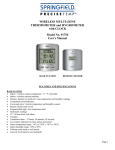
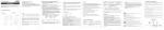
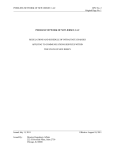
WIRELESS SOIL MOISTURE MONITOR WITH FREEZE ALERT
AND
INDOOR / WIRELESS OUTDOOR THERMOMETER
Model No. 91746 User’s Manual
REMOTE SOIL MOISTURE &
AIR TEMPERATURE SENSOR / BASE STATION
FEATURES AND SPECIFICATIONS
BASE STATION
•
•
•
•
•
•
•
•
•
•
Indoor air temperature / remote air temperature and soil moisture measurement
3 Channel – monitors temperature and soil moisture at up to 3 remote locations (additional remotes required)
High / low temperature alert for indoor and outdoor temperature
Indoor / outdoor temperature displayed in °F or °C
Memory function to recall highest/lowest temperature readings (MIN/MAX)
Indoor temperature range: 14°F to 158°F (-10°C to 70°C)
Temperature tolerance: +/- 2°F (+/- 1.1°C)
Low battery indicator
Table top or wall mount
Requires (2) AAA batteries
REMOTE SENSOR
• 433 MHz transmission frequency
• Transmission range up to 100 ft. (range may be shorter based on interference present)
• Temperature range: -4°F to 158°F (-20°C to 70°C)
• Temperature tolerance: +/- 2°F (+/- 1.1°C)
• Requires (2) AAA batteries
Notes:
1) Do not mix old and new batteries.
2) Do not mix alkaline, standard (carbon zinc), or rechargeable (nickel cadmium) batteries.
3) For maximum performance in normal conditions we recommend using good quality alkaline batteries.
When temperatures are below 0°F, alkaline batteries can lose power resulting in a loss of remote transmission. If you
reside in an area that experiences frequent temperatures near or below 0°F, we recommend using lithium batteries to
minimize the loss of
transmission.
TX
Battery
Compartment
Reset
BATTERY INSTALLATION AND SETUP
Remove the printed vinyl label from the LCD screen of the base station.
Position the remote sensor near the base station.
Open the battery compartment at the back of the base station.
Remove 2 screws from the back of the remote sensor and open the battery compartment. Slide the channel selector
switch to your desired channel. For the first remote you may select any channel, for additional remotes select any unused
channel.
• Insert (2) AAA batteries into the base station according to the polarity markings. Replace the battery compartment cover.
• The base station will show the current indoor temperature and the RF signal icon
(located to the left of the outdoor
temperature display) will flash for 3 minutes, indicating that the base station is ready to pick up the transmission from the
remote sensor.
• Insert (2) AAA batteries into the remote sensor according to the polarity markings.
• When the OUT temperature reading is displayed on the base station, registration of the remote sensor is complete.
• If you have registered more than one sensor, press the CH (channel) button on the base station to select the remote
channel you want displayed permanently. Or press CH until you see a circular arrow on the base station LCD display
under the channel number. The unit will then auto-scroll, changing from channel to channel every 5 to 10 seconds.
• Occasionally you may experience interference on a particular channel. If your base station has trouble picking up the
remote sensor signal, remove the batteries from the remote sensor, slide the channel selector switch to another unused
channel and re-install the batteries.
• Press the C/F button to display the temperature in °C or °F.
• After setup is complete, replace the battery compartment cover on the remote sensor. If the rubber gasket for the battery
compartment has become dislodged, position it properly to ensure a watertight seal. Re-install 2 screws. Do not over
tighten the screws.
Register the Moisture Sensor When the RF Signal Icon is not Showing
To register a remote sensor when the RF signal icon
is not showing on the base station LCD:
• Press and hold the CHANNEL button for 3-4 seconds until the RF signal icon is showing.
• Install the batteries in the new remote sensor or if the batteries have already been installed, press either the TX or RESET
button, which are located inside the remote sensor battery compartment.
•
•
•
•
Locating the Base Station and Moisture Sensor
• Choose a suitable place for the base station and remote outdoor sensor, within the transmission distance.
• Place the base unit near a window, but away from direct sunlight or sources of heat or air conditioning to ensure accurate
temperature readings.
• Gently push the ground spike into the soil at your desired location. If you feel strong resistance, try another spot as you
may have hit a stone or root. Recommended depths from the surface of the soil to the tip of the spike are 3” for an
average lawn and 4” for the average garden planting. Root depth can vary significantly with different vegetables,
shrubbery or plants. Mature plantings might have a deeper root system and younger plantings a shallower root system.
• For outdoor applications, if possible locate the moisture sensor out of direct sunlight. Exposure to direct sunlight will
affect the outdoor temperature reading.
• The location you choose is critical for maximizing the transmission range. The remote sensor is designed to transmit up
to 100 ft. unimpeded. Transmitting through walls, metal doors and metal framed windows may reduce the transmission
range. To optimize the transmission distance, the remote and base station should be positioned in a location that
minimizes these obstructions. Interference from other sources such as home security systems, wireless doorbells and
wireless home entertainment equipment may interrupt the transmission signal temporarily.
• Bring the remote sensor indoors during periods of snow, ice or extremely cold weather. Under these conditions the sensor
cannot perform its primary function of
soil moisture measurement and this will
prevent damage to the unit.
OPERATING INSTRUCTIONS
SOIL MOISTURE LEVEL
Indoor Temperature
Alert
Your moisture meter will indicate the
d ik
Th l l i h
i
b
C/F
moisture level of the soil at the tip of the
Indicator
hOutdoor
t t thTemperature
b tt
f /thChannel
b
t ti LCD
display along with the words DRY, DAMP or WET. 0 to 3 bars = dry soil. 4 to 7 bars = damp soil. 8 to 10 bars = wet soil.
SETTING THE AIR TEMPERATURE ALERTS
You can program your thermometer to sound an alert whenever the indoor or outdoor air temperature exceeds the upper or
lower pre-set level. The outdoor alert can be set for all remote channels.
Setting the Indoor Temperature Alert
and indoor temperature will be
• Press and hold the ALERT button for 3-4 seconds. The high temperature limit icon
flashing.
• To select the high temperature alert level press C/F or MIN/MAX.
and temperature will be flashing.
• Press ALERT and the low temperature limit icon
• Press C/F or MIN/MAX to select the low temperature alert level.
• Press ALERT to return to normal mode.
• Press ALERT to activate or de-activate the alert function. When the alert function is activated, both the high and low
limit icons will show.
Setting the Outdoor Temperature Alert
• Press and hold the ALERT button for 3-4 seconds.
• Press CHANNEL to select the channel on which you want to set the alert. (1, 2 or 3)
and outdoor temperature for the channel you selected will be flashing.
• The high temperature limit icon
• To select the high temperature alert level press C/F or MIN/MAX.
and temperature will be flashing.
• Press ALERT and the low temperature limit icon
• Press C/F or MIN/MAX to select the low temperature alert level.
• Press ALERT to return to normal mode.
• Press ALERT to activate or de-activate the alert function. When the alert function is activated, both the high and low
limit icons will show.
MIN/MAX TEMPERATURE MEMORY
•
•
•
Press the MIN/MAX button once to display the lowest indoor and outdoor temperatures recorded since last reset. MIN
is shown on the display.
Press MIN/MAX a second time to display the highest indoor and outdoor temperatures recorded since last reset. MAX
is shown on the display.
To clear and reset the min/max records, when either the MAX or MIN record is shown on the LCD display, press and
hold MIN/MAX for 2-3 seconds until the beep sounds.
TEMPERATURE TREND ARROWS
The arrows at the bottom, left of the temperature displays indicate the general temperature trend and whether it is rising,
stable or falling.
RESET
Your unit can be reset in case of malfunction. Push the RESET button at the back of the base unit. If you do not receive the
OUT temperature signal, open the battery compartment of the remote sensor and press either the TX or RESET button.
PURCHASING ADDITIONAL REMOTE SENSORS
The remote sensor for this unit is SPRINGFIELD P/N 91747. Additional sensors may be ordered directly from Springfield
Precision Instruments by calling 1-888-809-3284. Please have a major credit card ready when placing the call.
FCC STATEMENT OF COMPLIANCE
This device complies with Part 15 of the FCC rules. Operation is subject to the following two conditions:
1) This device may not cause harmful interference, and
2) This device must accept any interference received, including interference that may cause undesired operation.
Warning: Changes or modifications to this unit not expressly approved by the party responsible for compliance could void the
user’s authority to operate the equipment.
NOTE: This equipment has been tested and found to comply with the limits for a Class B digital device, pursuant to Part 15
of the FCC rules. These limits are designed to provide reasonable protection against harmful interference in a residential
installation. This equipment generates, uses and can radiate radio frequency energy and, if not installed and used in
accordance with the instructions, may cause harmful interference to radio communications. However, there is no guarantee
that interference will not occur in a particular installation. If this equipment does cause harmful interference to radio or
television reception, which can be determined by turning the equipment off and on, the user is encouraged to try to correct the
interference by one of more of the following measures:
• Reorient or relocate the receiving antenna.
• Increase the separation between the equipment and the receiver.
• Connect the equipment into an outlet on a circuit different from that to which the receiver is connected.
• Consult the dealer or an experienced radio/TV technician for help.
LIMITED WARRANTY
Springfield warrants this product to be free from defects in workmanship or material for a period of one year from the date of
purchase. ALL IMPLIED WARRANTIES, INCLUDING BUT NOT LIMITED TO WARRANTIES OF FITNESS
AND MERCHANTABILITY ARE HEREBY LIMITED IN DURATION TO A PERIOD ENDING ONE YEAR
FROM THE DATE OF PURCHASE. Some states do not allow limitations on how long an implied warranty lasts, so the
above limitation may not apply to you. This warranty gives you specific legal rights, which vary, from state to state. During
the warranty period, such defects will be repaired or the defective instrument will be replaced at our option. This warranty
does not cover damages through accident or misuse. IN ADDITION, SPRINGFIELD IS NOT RESPONSIBLE FOR
INCIDENTAL OR CONSEQUENTIAL DAMAGES INCURRED AS A RESULT OF DEFECT. Repair or replacement
will be made at our option without additional charge if the instrument is returned postpaid with $4.00 for return postage and
handling to:
76 Passaic Street, Wood-Ridge, NJ 07075-1091
1-888-809-3284
Made in China
©2008 Springfield Precision Instruments, Inc.
All Rights Reserved