1
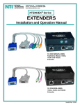
XTENDEX® Series ST-2FODVI-LC DVI Extender via Fiber Optic Cable Installation and Operation Manual FIBER-D-LCLC-50-xxM (Sold Separately) MAN115 Rev Date 06/29/2009 TRADEMARK XTENDEX is a registered trademark of Network Technologies Inc in the U.S. and other countries. COPYRIGHT Copyright © 2009 by Network Technologies Inc. All rights reserved. No part of this publication may be reproduced, stored in a retrieval system, or transmitted, in any form or by any means, electronic, mechanical, photocopying, recording, or otherwise, without the prior written consent of Network Technologies Inc, 1275 Danner Drive, Aurora, Ohio 44202. CHANGES The material in this guide is for information only and is subject to change without notice. Network Technologies Inc reserves the right to make changes in the product design without reservation and without notification to its users. TABLE OF CONTENTS Introduction...................................................................................................................................................................... 1 System Requirements ................................................................................................................................................. 3 Installation ....................................................................................................................................................................... 3 Self-EDID Programming Procedure ............................................................................................................................ 6 Troubleshooting............................................................................................................................................................... 7 Product Specifications..................................................................................................................................................... 7 Warranty Information....................................................................................................................................................... 8 TABLE OF FIGURES Figure 1- Schematic connection diagram of optical DVI extension modules...................................................................................... 2 Figure 2- Connection of the power adapter to the transmitter............................................................................................................ 3 Figure 3- Connection of the power adapter to the receiver ................................................................................................................ 4 Figure 4- Connection of optical fibers ................................................................................................................................................ 4 Figure 5- Connection of the transmitter to the DVI source ................................................................................................................. 5 Figure 6- Connection of the receiver to the display............................................................................................................................ 5 Figure 7- Position of EDID LED and PRGM button............................................................................................................................ 6 NTI XTENDEX DVI FIBER OPTIC EXTENDER INTRODUCTION The XTENDEX® ST-2FODVI-LC DVI Extender via Fiber Optic Cable locates a single link digital DVI display away from a computer up to 4,920 feet (1,500 meters) using duplex singlemode fiber optic cable and 1,640 feet (500 meters) using duplex multimode fiber optic cable with LC style connectors. Each extender consists of a transmitter that connects to a computer and a receiver that connects to a monitor. Features: • Ideal solution for digital signage applications. • Supports computer resolutions to 1920x1200. • Signal transmission via two strand single-mode or multimode LC fiber optic cable – no RF interference. o Using single-mode cable, extend to 4,920 feet. o Using multi-mode cable, extend to 1,640 feet. • Small form factor – allowing for easy connection and placement. • Cables can be installed in conduit prior to extender installation. • EDID learning for the support of any DVI display device. • Low RFI/EMI for sensitive applications. • No software to install. The DVI Optical Extender is the ideal solution for a wide range of applications. Examples include: • Remote DVI display monitoring for medical, military, aerospace, industrial and traffic control applications. • Digital Flat Panel Displays (FPD), Plasma Display Panels (PDP) and projectors in conference rooms and auditoriums. • Kiosks with digital FPDs. • Color LED signboards, FPDs and PDPs for information display at stadiums. 1 NTI XTENDEX DVI FIBER OPTIC EXTENDER Materials Included: • • ST-2FODVI-LC DVI Extender modules: One (1) pair • User’s Manual 100-240VAC, 50 or 60Hz-5VDC/1A AC Adapters (2) Materials required but not supplied: Fiber optic cable to run between the receiver and transmitter- Available from NTI: FIBER-D-LCLC-50-xxM duplex multi-mode LC 50-Micron Fiber Optic Cable (xx = 20,30,40,50,100,300,500 meters) Use duplex multimode LC 50-micron fiber optic cable to extend up to 1640 feet (not supplied) LC Style Connectors Use a duplex singlemode LC 9-micron fiber optic cable to extend up to 4920 feet (not supplied) AC ADAPTER (supplied) PC (VIDEO SOURCE) ST-2FODVI-LC TRANSMITTER AC ADAPTER (supplied) ST-2FODVI-LC RECEIVER DVI MONITOR Figure 1- Schematic connection diagram of optical DVI extension modules 2 NTI XTENDEX DVI FIBER OPTIC EXTENDER System Requirements Hardware requirements • Graphic controller with a DVI port in your PC, SUN or Mac systems. It should support the maximum graphic resolution of displays to be connected. • No special requirements for memory size, CPU speed and chipsets, if you’ve already properly installed your DVI graphic controllers. AC/DC Power Adapter Technical Advisory The transmitter (Tx) module of the ST-2FODVI-LC may be powered with either the included AC power adapter or your graphic card, depending on the power supply capability of the graphic card you are using. However, the receiver (Rx) module must be supplied by the AC power adapter. Note: In general, most laptops or desktop PCs with PCI Express graphic card require using the supplied 5VDC power adapter for the transmitter module. INSTALLATION Important: Please use the installation procedure below. Improper or no operation may result if the start-up sequence is not correctly followed. 1. Carefully unpack the material included. 2. Plug the included 5VDC power adapter into an AC outlet. Plug the 5V power adapter to the power jack of the transmitter. Ensure the blue LED remains illuminated after blinking twice. BLUE LED ST-2FODVI-LC TRANSMIITTER Figure 2- Connection of the power adapter to the transmitter Note: You don’t need to connect the power adapter to the transmitter if the graphic source provides enough power to operate the transmitter. Please, refer to AC Power Adapter Technical Advisory in the “System Requirements” section. 3 NTI XTENDEX DVI FIBER OPTIC EXTENDER 3. Check if the maximum resolution of the display is UXGA (1600x1200). Otherwise, follow the instructions for Self-EDID Programming Procedure on page 6. 4. Plug the included 5VDC power adapter into an AC outlet. Plug the 5V power adapter to the power jack of the receiver. Ensure the blue LED is illuminated. BLUE LED ST-2FODVI-LC RECEIVER Figure 3- Connection of the power adapter to the receiver 5. Connect duplex optical fiber (not supplied) between the transmitter and the receiver as shown in figure 4 Use duplex multimode LC 50-micron fiber optic cable to extend up to 1640 feet (not supplied) Use a duplex singlemode LC 9-micron fiber optic cable to extend up to 4920 feet (not supplied) AC ADAPTER (supplied) ST-2FODVI-LC TRANSMITTER AC ADAPTER (supplied) ST-2FODVI-LC RECEIVER Figure 4- Connection of optical fibers Note: Both single-mode and multi-mode fiber are applicable to ST-2FODVI-LC up to 1640 feet. Beyond 1640 feet, singlemode fibers must be used. 4 NTI XTENDEX DVI FIBER OPTIC EXTENDER 6. Plug the transmitter to the DVI receptacle of the DVI source (such as a PC). ST-2FODVI-LC TRANSMITTER PC (VIDEO SOURCE) Figure 5- Connection of the transmitter to the DVI source Note: We recommend NOT to use any intermediate cable or adapter between the transmitter and the DVI source to avoid undesirable performance degradation. 7. Plug the receiver into the DVI receptacle of the display. ST-2FODVI-LC RECEIVER DVI MONITOR Figure 6- Connection of the receiver to the display 8. Power ON the PC and the display. ! Caution: When you touch the surface of modules, the surface of modules may be hot. This is normal. 5 NTI XTENDEX DVI FIBER OPTIC EXTENDER Self-EDID Programming Procedure The video source generally requires communication of display information (EDID). Display information (EDID) contains resolution and timing information for your display. ST-2FODVI-LC supports Self-EDID programming. Self-EDID programming means that the EDID from the display is stored in the transmitter. Use THE Self-EDID programming feature if the resolution of the display is not UXGA(1600x1200) because the default resolution setting of the ST-2FODVI-LC is preset at 1600x1200, 60Hz. Follow these steps to record the EDID of the display into the transmitter unit. Note1 : If you know that EDID is not required by the video source, Self-EDID programming is not necessary. Note2 : The default EDID setting of the ST-2FODVI-LC is the VESA standard UXGA (1600x1200) 60Hz. 1. Power ON the display. Note: The transmitter should not be connected to the display. 2. Plug the included 5VDC power adapter into an AC outlet. Insert the 5VDC power adapter into the transmitter. 3. Push the EDID PRGM button of the transmitter with a narrow pin or small paper clip. The Self-EDID LED will blink twice and then be turned OFF. If this does not happen, disconnect the 5VDC power from the transmitter, wait 10 seconds, reconnect the power, and try again. Self EDID LED EDID-PRGM button Figure 7- Position of EDID LED and PRGM button 4. With the display and transmitter still powered, connect the transmitter to the display, not to the PC. The LED on the transmitter will begin to blink rapidly. Blinking indicates the transmitter is reading the EDID. The LED will blink for about 15 sec. When the blinking stops, the monitor EDID has been recorded. 5. Disconnect the transmitter from the display. 6 NTI XTENDEX DVI FIBER OPTIC EXTENDER TROUBLESHOOTING The monitor displays only black screen. − Ensure that all plugs and jacks used by external power supplies are firmly connected. Ensure the blue LED is illuminated. − Ensure that the DVI ports are firmly plugged-in to the PC and display. − Ensure that the transmitter and receiver modules are connected correctly to the PC and display, respectively. − Check if the PC and display are powered ON and properly booted. − Reset the system by un-plugging and re-plugging the transmitter DVI port or receiver DVI port, or by un-plugging and replugging the power cord plugs of the transmitter and receiver modules. − Re-boot up the system while connecting the optical DVI extension module. Screen is distorted or displays noises. − Check if the graphic resolution is properly set. Go to the display properties of Windows and check the settings. − Ensure that the resolution is set to no greater than 1920x1200 at 60Hz refresh ratio. − Reset the system. Disconnect and reconnect the optical DVI cables or 5V power adapters. For technical service, contact Network Technologies Inc at (800) 742-8324 (800-RGB-TECH) or (330) 562-7070 or visit our website at http://www.networktechinc.com PRODUCT SPECIFICATIONS Fiber Optic DVI Extension Modules DVI standard compliance S u p p o r t s D V I 1 . 0 , f u l l y implemented by fiber-optic communication and DDC2B by virtual DDC. Video Connectors DVI-I Single-link Maximum Resolution 1920x1200 at 60Hz Extension Limit (multi-mode fiber) 1640 feet (500 meters) Extension Limit (single-mode fiber) 4920 feet (1500 meters) Graphic transmission bandwidth Supports up to WUXGA at 60Hz, or 1.65Gbps bandwidth per graphic channel. Fiber-optic connection two LC receptacles so as to be connected with one LC duplex single or multimode fibers, having 9(8)/125ìm or 62.5(50)/125ìm core. DDC connection Virtual DDC by Auto EDID programming Environmental Conditions Operating temperature 32°F-122°F (0°C to 50°C) Storage temperature 14°F to 185°F (-10°C to 85°C). Humidity 5% to 85% non-condensing RH Atmospheric pressure 500 hpa to 1060 hpa General Transmitter and Receiver Power 100V or 240V at 50 or 60Hz-5VDC/1.0A via AC Adapters (2) Dimensions WxDxH (In.) 1.5x2.7x0.6 7 NTI XTENDEX DVI FIBER OPTIC EXTENDER WARRANTY INFORMATION The warranty period on this product (parts and labor) is two (2) years from the date of purchase. Please contact Network Technologies Inc at (800) 742-8324 (800-RGB-TECH) or (330) 562-7070 or visit our website at http://www.networktechinc.com for information regarding repairs and/or returns. A return authorization number is required for all repairs/returns. Dispose of Old Electrical & Electronic Equipment (Applicable in the European Union and other European countries with separate systems) This symbol on the product or on its packaging indicates that this product shall not be treated as household waste. Instead it shall be handed over to the applicable collection point for the recycling of electrical and electronic equipment. By ensuring this product is disposed of correctly, you will help prevent potential negative consequences for the environment and human health, which could otherwise be caused by inappropriate waste handling of this product. The recycling of materials will help to conserve natural resources. For more detailed information about recycling of this product, please contact your local city office, your household waste disposal service or the shop where you purchased the product. PRODUCT: ST-2FODVI-LC SERIAL NO.: DATE: INSPECTED BY: MAN115 8 Rev. 06/29/07