1
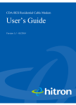
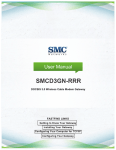
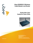
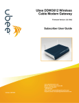
SMC8014W-G User Manual Page 1 of 39 Copyright Information furnished by SMC Networks, Inc. (SMC) is believed to be accurate and reliable. However, no responsibility is assumed by SMC for its use, nor for any infringements of patents or other rights of third parties which may result from its use. No license is granted by implication or otherwise under any patent or patent rights of SMC. SMC reserves the right to change specifications at any time without notice. Copyright © 2009 by SMC Networks, Inc. 20 Mason Irvine, California 92618 All rights reserved. Trademarks SMC is a registered trademark of SMC Networks, Inc. Other product and company names are trademarks or registered trademarks of their respective holders. Page 2 of 39 TABLE OF CONTENTS CHAPTER 1 | Introduction Features and Benefits Package Contents Minimum Requirements CHAPTER 2 | Getting to know the EZ Connect™ Wireless Cable Modem Gateway LED Indicators Rear Panel Description Resetting and Restoring the EZ Connect™ Wireless Cable Modem Gateway CHAPTER 3 | Installation Basic Installation Procedure CHAPTER 4 | Configuring your Computer Configuring Windows 95/98/Me Configuring Windows 2000 Configuring Windows XP Configuring Windows Vista Configuring a Macintosh Computer CHAPTER 5 | Configuring the EZ Connect™ Wireless Cable Modem Gateway Browser Configuration Disable Proxy Connection Accessing the EZ Connect™ Wireless Cable Modem Gateway Web Management CHAPTER 6 | Navigating the Web-based Administration System LAN Wireless NAT Firewall Tools Status APPENDIX A | Technical Specifications APPENDIX B | Compliances APPENDIX C | Technical Support Page 3 of 39 CHAPTER 1 | Introduction Congratulations on your purchase of the EZ Connect™ Wireless Cable Modem Gateway. SMC is proud to provide you with a powerful yet simple communication device for connecting your local area network (LAN) to the Internet. Features and Benefits Internet connection to cable modem service via an integrated cable modem port Local network connection via 10/100 Mbps Ethernet ports, USB 1.1 port, or 54 Mbps wireless 802.11g - interoperable with multiple vendors Wireless WEP, WPA, and WPA2 encryption, Hide SSID, and MAC Filtering DHCP for dynamic IP configuration, and DNS for domain name mapping Firewall with Stateful Packet Inspection, client privileges, hacker prevention, DoS, and NAT User-definable application-sensing tunnel supports applications requiring multiple connections Built-in Parental controls allow you to limit certain web sites – configurable by time and day Easy setup through a web browser on any operating system that supports TCP/IP Compatible with all popular Internet applications Page 4 of 39 Package Contents Before installing the EZ Connect™ Wireless Cable Modem Gateway, verify that you have the items listed below. Also be sure that you have the necessary cabling. If any of the items are missing or damaged, contact your local SMC distributor. 1 - EZ Connect™ Wireless Cable Modem Gateway 1 - Power adapter (12V/1.25A) 1 - CAT-5 Ethernet cable Installation CD, including: o User Guide o USB Drivers If possible, retain the carton and original packing materials in case there is a need to return the product. System Requirements You must meet the following minimum requirements: Provisioned Internet access from a cable operator that has approved the SMC8014W-G A computer equipped with a wired network adapter with TCP/IP installed A Java-enabled web browser, such as Microsoft Internet Explorer 5.5 or above Windows 98 Second Edition or higher is required for USB driver support. Page 5 of 39 CHAPTER 2 | Getting to Know the EZ Connect™ Wireless Cable Modem Gateway The EZ Connect™ Wireless Cable Modem Gateway is the perfect all-in-one solution for the home or business environment. This full-featured device has: An approved DOCSIS 1.1 and 2.0 cable modem Advanced SPI Firewall Gateway High-speed 54 Mbps 802.11g Wireless Access Point Comprehensive LEDs for network status and troubleshooting Reset Button 4 – 10/100 Mbps Auto-Sensing LAN ports with Auto-MDI/MDIX feature 1 – USB 1.1 LAN Port for PC connectivity NOTE: Cable modems can provide up to 38 Mbps downstream and 10 Mbps upstream. However, you should note that the actual rate provided by specific service providers may vary dramatically from these upper limits. LED Indicators The Gateway includes LED indicators on the front panel that simplify installation and network troubleshooting. LABEL Power LED COLOR Green Diag Green Cable Green Traffic Green WLAN LAN (1-4) Green Green USB Green Page 6 of 39 ON FLASHING Power is supplied to the Gateway N/A System Failure. Reboot Gateway Successfully connected to the RF network – upstream ranging completed Cable Modem has finished CMTS registration. Internet connectivity completed Wireless Link Connected at 10 or 100 Mbps USB port connected OFF Power is not supplied to the Gateway N/A Normal Operation Attempting to connect to RF network N/A Attempting to register with CMTS N/A Data transmitting Data transmitting Data transmitting No Wireless Link No Ethernet link detected No USB link detected Rear Panel Description Power LAN Ports CATV Connector Reset Button USB Item Power Reset LAN 1-4 USB CATV Description Connect the included power adapter to this port. Use this button to reset the power or restore the default factory settings. Four 10/100 Auto-sensing switch ports (RJ-45). Connect devices on your local area network to these ports (such as a PC, hub, or switch). Connect a USB Cable from your PC to this port. Connect your cable line to this port. Rebooting and Restoring the EZ Connect™ Wireless Cable Modem Gateway The Reset button is located on the rear panel of the Gateway. Use a paper clip or a pencil tip to push the Reset button. Reboot If the Gateway is having problems connecting to the Internet, simply hold down the reset button for less than 1 seconds then release. Restore Factory Defaults If rebooting the Gateway does not resolve your issue, then you can follow these steps: 1. Leave power plugged into the Gateway. 2. Locate the reset button on the back panel, press and hold button for at least 10 seconds. 3. Release reset button. Page 7 of 39 CHAPTER 3 | Installation The EZ Connect™ Wireless Cable Modem Gateway can be installed in any location where you have cable Internet access, and your cable Internet service provider has approved the Gateway. To confirm you meet these 2 criteria points, please contact your cable operator. For general installation please follow the guidelines outlined below to best performance: Allow sufficient air flow around the device to assist in keeping the device as cool as possible Do not place the Gateway in a dusty or wet environment. For optimum wireless performance, install the Gateway away from other electronic devices, such as Monitors / TV / 2.4GHz Cordless Phones. These devices can hamper your wireless throughput and distance. Basic Installation Procedure 1. Connect the LAN: You can connect the Gateway to your PC, or to a hub or switch. Run Ethernet cable from one of the LAN ports on the rear of the Gateway to your computer’s network adapter or to another network device. You can use either a standard straight through or crossover Ethernet cable since the Gateway incorporates Auto-MDI/MDIX functionality. 2. Connect the WAN: Connect a coaxial cable to the CATV port on the back of the Gateway from a cable port located in your home. When connecting to the CATV port, use only manufactured coaxial patch cables with F-type connectors at both ends for all connections. Note: If this modem was NOT installed by your cable provider (ISP) or is being used to replace another cable modem – please contact your Cable Operator to register the SMC8014W-G. If the modem is not registered with your cable operator it will be unable to connect to the cable network system. 3. Power on: Connect the power adapter to the Gateway. Warning: Only use the power adapter that was provided with the Gateway! Using another power adapter may damage your unit and void the warranty. Page 8 of 39 CHAPTER 4 | Configuring your Computer The information outlined in this chapter will guide you through the configuration for the following Operating Systems: Windows 95/98 Windows Me Windows 2000 Windows XP Windows Vista Apple Macintosh Configuring Windows 95/98/Me 1. Access your Network settings by clicking [Start], choose [Settings], and then select [Control Panel]. 2. In the Control Panel, locate and double-click the [Network] icon. 3. Highlight the TCP/IP line that has been assigned to your network card on the [Configuration] tab of the [Network] properties window. (see network dialog box to the right) 4. Next, click the [Properties] button to view that adapter’s TCP/IP settings. 5. From the TCP/IP Properties dialog box, click the [Obtain an IP address automatically] option. (see TCP/IP dialog box to the right) 6. Next click on the [Gateway] tab and verify the Gateway field is blank. If there are IP addresses listed in the Gateway section, highlight each one and click [Remove] until the section is empty. 7. Click the [OK] button to close the TCP/IP Properties window. 8. On the Network Properties Window, click the [OK] button to save these new changes. NOTE: Windows may ask you for the original Windows installation disk or additional files. Check for the files at c:\windows\options\cabs, or insert your Windows CD-ROM into your CD-ROM drive and check the correct file location, for example, D:\win98, D:\win9x. (In this example “D” is your CD-ROM drive). 9. Windows may prompt you to restart the PC. If so, click the [Yes] button. If Windows does not prompt you to restart your computer, do so anyway to ensure your settings. Page 9 of 39 Configuring Windows 2000 1. Access your Network settings by clicking [Start], choose [Settings], and then select [Control Panel] 2. In the Control Panel, locate and doubleclick the [Network and Dial-up Connections] icon 3. Locate and double-click the [Local Area Connection] icon for the Ethernet adapter that is connected to the Gateway. When the Status dialog box window opens, click the [Properties] button. 4. On the [Local Area Connection] Properties box, verify the box next to Internet Protocol (TCP/IP) is checked. Then highlight the Internet Protocol (TCP/IP), and click the Properties button. 5. Select Obtain an IP address automatically to configure your computer for DHCP. Click the [OK] button to save this change and close the Properties window. 6. Click the [OK] button again to save these new changes. 7. Reboot your PC. Configuring Windows XP The following instructions assume you are running Windows XP with the default interface. If you are using the Classic interface (where the icons and menus look like previous Windows versions), please follow the instructions for Windows 2000 outlined above. 1. Access your Network settings by clicking [Start], choose [Control Panel], select [Network and Internet Connections] and then click on the [Network Connections] icon. 2. Locate and double-click the Local Area Connection icon for the Ethernet adapter that is connected to the Gateway. Next, click the [Properties] button. 3. On the [Local Area Connection] Properties box, verify the box next to Internet Protocol (TCP/IP) is checked. Then highlight the Internet Protocol (TCP/IP), and click the Properties button. 4. Select Obtain an IP address automatically to configure your computer for DHCP. Click the [OK] button to save this change and close the Properties window. Page 10 of 39 5. Click the [OK] button again to save these new changes. 6. Reboot your PC. Configuring Windows Vista The following instructions assume you are running Windows Vista with the default interface. If you are using the Classic interface (where the icons and menus look like previous Windows versions), please follow the instructions for Windows 2000 outlined above. 1. Access your Network settings by clicking [Start], choose [Control Panel], select [Network and Internet Icon] and then click on the [View Networks Status and tasks. Click on the [Management Networks Connections] 2. Locate and Right click the Local Area Connection icon. Click the [Properties] button. Next, click [Continue]. 3. On the [Local Area Connection] Properties box, verify the box next to Internet Protocol (TCP/IPv4) is checked. Then highlight the Internet Protocol (TCP/IPv4), and click the Properties button. 4. Select Obtain an IP address automatically to configure your computer for DHCP. Click the [OK] button to save this change and close the Properties window. Page 11 of 39 5. Click the [OK] button again to save these new changes. Page 12 of 39 Configuring a Macintosh Computer You may find that the instructions here do not exactly match your screen. This is because these steps and screen shots were created using Mac OS 10.2. Mac OS 7.x and above are all very similar, but may not be identical to Mac OS 10.2. 1. Pull down the Apple Menu. Click System Preferences and select Network. 2. Verify that adapter connected to SMC8014W-G is selected in the Show field. 3. On the TCP/IP tab, select “Using DHCP” in the Configure field. 4. Close the TCP/IP dialog box by clicking on “Apply Now”. Page 13 of 39 CHAPTER 5 | Configuring the EZ Connect™ Wireless Cable Modem Gateway After you have configured TCP/IP on a client computer, use a web browser to configure the EZ Connect™ Wireless Cable Modem Gateway. The Gateway can be configured by any Javasupported browser including Internet Explorer 5.0 or above, or Netscape Navigator 5.0 or above. Using the web management interface, you can configure the Gateway features and view its settings. Before you attempt to log into the Gateway’s Web-based Administration, please verify the following: 1. Your browser is configured properly. (see below) 2. Disable any firewall or security software that may be running. 3. Confirm that you have a [link] LED where your computer is plugged into the Gateway. If you don’t have a [link] light, try another cable. Browser Configuration Confirm that your browser is configured for a direct connection to the Internet. This is configured through the [Tools] then [Options/Preferences] section of your browser. Disable Proxy Connection You will also need to verify that the “HTTP Proxy” feature of your web browser is disabled. This is so that your web browser will be able to view the web-based configuration pages. The following steps are for Internet Explorer and for Netscape. Determine which browser you use and follow the appropriate steps. Internet Explorer (5.0 or above) 1. Open Internet Explorer. Click [Tools], and then select [Internet Options]. 2. In the [Internet Options] window, click the [Connections] tab. 3. Click the [LAN Settings] button. 4. Clear all the check boxes and click [OK] to save these LAN settings changes. 5. Click [OK] again to close the [Internet Options] window. NOTE: To ensure proper screen refresh after a command entry, be sure that Internet Explorer 5.0 is configured as follows: Under the menu “Tools/Internet Options/General/Temporary Internet Files/Settings,” the setting for “Check for newer versions of stored pages” should be “Every visit to the page.” Page 14 of 39 Accessing the EZ Connect™ Wireless Cable Modem Gateway’s Web Management To access the EZ Connect™ Wireless Cable Modem Gateway’s web-based management screens, follow the steps below: 1. Launch a web-browser. NOTE: Your computer does not have to be ONLINE to configure the EZ Connect™ Wireless Cable Modem Gateway. 2. In the Address Bar, type: http://192.168.0.1 3. When the Gateway’s Login screen appears, enter the default username and password, and click the [Login] button to access the Gateway. Default Username and Password: USERNAME: cusadmin PASSWORD: password NOTE: Usernames and Passwords are case sensitive 4. Once logged into the Gateway’s web-based administration screen, there are several options and features which can be configured, as outlined in the following chapter. Page 15 of 39 CHAPTER 6 | Navigating the Web-based Administration The EZ Connect™ Wireless Cable Modem Gateway’s management interface allows you to configure both basic and advanced features and options. Some of these advanced functions include: hacker attack detection, IP and MAC address filtering, intrusion detection, port forwarding setup, virtual DMZ hosts, as well as other advanced functions. Making Configuration Changes Once a configuration change has been made on a page, be sure to click the [Apply] or [Next] button at the bottom of the page to enable the new setting. SYSTEM Password Settings To access the Password Settings configuration page, click on [System] link and then click on the [Password Settings] link on the Side Navigation bar. A new password can be configured for the [cusadmin] account in this section. The Idle Time Out value can also be specified on this page. The default Idle Time Out value is 10 minutes. If there is no activity after this amount of time, the administrator will automatically be logged out. If your password is lost or you cannot gain access to the user interface, press the Reset button on the rear panel (holding it down for at least five seconds) to restore the factory defaults. NOTE: After a reset, all custom settings will be deleted! LAN From this section you can configure the following settings: The PRIVATE LAN IP settings, including IP Address, Subnet Mask, and Domain Name. Enable or Disable the integrated DHCP server Configure the DHCP Lease time for your DHCP clients To access the LAN configuration page, on the Side Navigation bar, click on [LAN] link. Page 16 of 39 LAN IP Use the LAN section to configure the LAN IP address for the Gateway and to enable the DHCP server for dynamic client address allocation. You can also configure the Lease Time for the DHCP clients on your network. Private LAN IP Settings Define the Gateway’s private LAN settings. The IP address configured in the example below (192.168.0.1) is the Gateway’s (default setting: 192.168.0.1). NOTE: Port Forwarding and Access Control rules will be based on the network scope defined here. If either of these types of rules were previously setup and the Private LAN IP address is changed, those rules will need to be recreated to reflect the new Private LAN IP network. DHCP Server Settings The Gateway’s DHCP Server can be enabled/disabled here. Also the DHCP client Lease Time can be adjusted from the default setting of “One Week.” The Gateway functions as a DNS proxy by default. WIRELESS This section allows you to configure the Gateway’s built-in 54 Mbps 802.11g Access Point. To setup the wireless connections, you will need to do define the Service Set Identifier (SSID), Channel, Encryption options, and other optional settings. To access the Wireless Settings page shown below, on the Side Navigation bar, click on [Wireless] link. The Wireless Mode can be set to Mixed (default), 11B only, 11B+ only, or 11G only. Also, the Gateway’s wireless interface can be disabled if not being used. Page 17 of 39 Channel and SSID You must specify a common radio channel and SSID (Service Set ID) to be used by the Gateway and all of your wireless clients. Be sure you configure all of your clients to the same values. To access the Channel and SSID configuration page, on the Side Navigation bar, click on [Wireless] link and then click on the [Channel and SSID] link. SSID: This is the Wireless ID or Service Set ID of your wireless network. This should be set to the same value as the other wireless devices in your network. NOTE: The SSID is case sensitive and can consist of up to 32 alphanumeric characters. Channel: The radio channel through which the Gateway communicates to clients over the wireless network. NOTE: If you are not getting good wireless performance try another wireless channel – because the Gateway operates in the 2.4GHz spectrum – it can be affected by some other products, such as cordless phones. Hide SSID: This option will cause the Gateway to not broadcast its SSID. By selecting this option, wireless clients will not be able to use their Site Survey feature to locate this wireless network. Encryption If you are transmitting sensitive data across wireless channels, you should enable either Wired Equivalent Privacy (WEP) or WiFi Protected Access (WPA) encryption. Encryption requires you to use the same set of encryption/decryption keys for the Gateway and all of your wireless clients. Page 18 of 39 To access the Encryption configuration page, on the Side Navigation bar, click on [Wireless] link and then click on the [Encryption] link. WEP Select [WEP] from the [Encryption Type] drop down menu. Select the Automatic, Open System, or Shared Key from the [WEP Authentication Type] drop down menu. You can choose between standard 64-bit or 128-bit encryption keys. Below are the configuration options for 64-bit WEP. A passphrase or a manual key can be used. NOTE: To enter a manual WEP key you will need to enter hexadecimal values (A-F and 0-9). To automatically generate a 64-bit WEP key, enter in a Passphrase (keyword - ex. Home) and click the [Generate Keys] option. Once you do this, the Gateway will dynamically generate 4 keys. Simply configure the Default Key to the one key that you will be using across your Page 19 of 39 network. On the wireless clients, you can use the passphrase option, and client utility will generate the same 4 keys – or you can manually type in the selected KEY that is configured on the Gateway. For more security, you can use 128-bit WEP encryption. To use this mode, click the [128 Bit Encryption] option and the configuration section will be displayed. You can manually enter in the 26-digit hexadecimal key or use the passphrase option to generate random dynamic keys. NOTE: If you are having a difficult time getting the wireless connection up after enabling WEP – please confirm that you have configured the SAME WEP key on both the Gateway and Client card. WPA-PSK Select [WPA-PSK] from the [Encryption Type] drop down menu. Next, enter a passphrase value between 8 and 63 characters in the [WPA Passphrase] field. WPA2-PSK Select [WPA2-PSK] from the [Encryption Type] drop down menu. Next, enter a passphrase value between 8 and 63 characters in the [WPA Passphrase] field. MAC Filtering The Gateway can allow the wireless client stations to connect over a wireless connection in 2 different ways: 1. By allowing all wireless stations access; 2. Or by allowing only Trusted PCs. Page 20 of 39 To access the MAC Filtering configuration page, on the Side Navigation bar, click on [Wireless] link and then click on the [MAC Filtering] link. You can also configure a [Device Name] that is associated with a specific MAC address. In doing this, you can easily recognize the computers that you are in your access list. NOTE: MAC filtering only applies to Wireless Clients. NAT Network Address Translation (NAT) allows multiple users at your local site to access the Internet through a single public IP address. Port Forwarding The Gateway supports port forwarding that enables customers to host servers on their LAN. You can configure this feature to redirect the external service request to the appropriate internal server and port. For example, if you are running a WEB server, you can configure all traffic on port 80 to be redirected to the IP address of the WEB server running on your network. To access the Port Forwarding configuration page, on the Side Navigation bar, click on [NAT] link and then click on the [Port Forwarding] link. Page 21 of 39 This Port Forwarding function supports 2 types of Services: Predefined Service Customer Defined Service Predefined Service The Predefined Service option has a pull-down menu with several popular Service Applications, such as HTTP (80), FTP (20/21), and AIM/ICQ (5190). To configure Port Forwarding with a Predefined Service rule, follow the steps below: 1. Select the [Service] that you want to have access through the firewall to your LAN from the pull-down menu. 2. Enter in the [LAN Server IP] for the LAN PC that is running this service or application 3. You can also configure [Remote IPs] option to allow access to this specific port from the WAN side. This can be configured for 3 different access types: a. Any IP Address [Any] – choose this option to allow access from any public IP address. b. Single IP Address [Single Address] – choose this option to only allow access from a single public IP address. c. IP Address Range [Address Range] – choose the option to only allow a range of public IP addresses. 4. Click the [Apply] button to save your changes and return to the Port Forwarding main screen Customer Defined Service Rule (Custom) The Customer Defined Service section allows you to custom configure a Port Forwarding rule with any Traffic type (TCP/UDP/TCP and UDP), Public Port, and Private Port. Page 22 of 39 To configure this custom option, please follow the steps below: 1. Enter in a Description [Name] for this custom setting 2. Configure the Traffic or Data [Type] that you want to forward. The options are TCP | UDP | TCP/UDP. 3. Set the [LAN Server IP] of the PC that you want this traffic/data redirected to 4. You can also configure [Remote IPs] option to limit access to this specific port from the WAN side. This can be configured for 3 different access types: a. Any IP Address [Any] – choose this option to allow access from any public IP address. b. Single IP Address [Single Address] – choose this option to only allow access from a single public IP address. c. IP Address Range [Address Range] – choose the option to only allow a range of public IP addresses. 5. Set the [Start Public Port] and [End Public Port] that this application will use on the WAN (Internet) side. The Gateway will listen for incoming traffic/data to its WAN IP on these ports. 6. Set the [Private Ports] that the Gateway will forward this traffic to on the LAN. If there is a range of ports, enter the starting private port in [Private Ports], select [Enable Port Range] checkbox, and the Gateway will automatically calculate the end private port. The LAN PC server will listen for traffic/data on this/these ports. Below is an example setting for a Web server on an Internet connection, where port 80 is blocked from the WAN side, but port 8000 is available. Name: Type: LAN Server IP: Remote IPs: Public Port: Private Port: Web Server TCP 192.168.0.100 Any (allow access to any public IP) 8000 80 With this configuration, all HTTP (Web) TCP traffic on port 8000 from any IP Address from the WAN side will be redirected through the firewall to the Internal Server (192.168.0.100) on port 80. Page 23 of 39 NOTE: This configuration is useful because you don’t have to reconfigure your web server to accept traffic on a different port, this configuration can be done on the Gateway. FIREWALL The Gateway provides a stateful inspection firewall (SPI), which is designed to protect against Denial of Service (DoS) attacks. Its purpose is to allow a private local area network (LAN) to be securely connected to the Internet. To provide a flexible solution, the firewall section has the following features: Firewall Enable/Disable To access the Security Settings configuration page, on the Side Navigation bar, click on [Firewall] link. To enable this feature, check the [Enable Firewall Module] checkbox. Access Control The Access Control section allows for blocking services on the private LAN from accessing the Internet. Access Rules can be configured to a specific LAN IP Address or a range of LAN IP Addresses. To access the Access Control configuration page, on the Side Navigation bar, click on [Firewall] link and then click on the [Access Control] link. To enable this feature, check the [Enable Access Control] checkbox. For convenience, there are two filtering options: Predefined Filtering Customer Defined Filtering Page 24 of 39 Predefined Filtering Access Rule: 1. On the Side Navigation bar, click on [Firewall] then select [Access Control] 2. Under the Predefined Section, click on the [Add] button 3. On the Predefined Filter page, select the service that you want to block from the pulldown menu 4. Select the [LAN IPs] to which you want this access rule to apply. You can choose to apply this rule to Any IP Address, a Single IP Address, or a Range of IP Addresses. a. Any IP Address [Any] – choose this option to block all LAN clients. You do not need to configure the [Start IP] or [End IP] options. b. Single IP Address [Single address] – choose this option to block a single LAN client. Enter the LAN IP address of the PC in the [Start IP] field. c. IP Address Range [Address Range] – choose this option to block a range of LAN clients. Enter the starting LAN IP address in the [Start IP] field and the ending LAN IP address of the range you want in the [End IP] field. 5. When your configuration is complete, click the [Apply] button to save your changes and return to the main Access Control page. Customer Defined Filtering Access Rule (Custom): 1. On the Side Navigation bar, click on [Firewall] then select [Access Control]. 2. Under the Customer Defined Section, click on the [Add] button. 3. On the Customer Defined Filter page, define a Name for the service/application that you want to block. NOTE: The Name is only for reference purposes. 4. Select the protocol type from the pull-down menu that you would like to block. The options are TCP | UDP | TCP/UDP. Page 25 of 39 5. Select the [LAN IPs] to which you want this access rule to apply. You can choose to apply this rule to Any IP Address, a Single IP Address, or a Range of IP Addresses. a. Any IP Address [Any] – choose this option to block all LAN clients. You do not need to configure the [Start IP] or [End IP] options. b. Single IP Address [Single address] – choose this option to block a single LAN client. Enter the LAN IP address of the PC in the [Start IP] field. c. IP Address Range [Address Range] – choose this option to block a range of LAN clients. Enter the starting LAN IP address in the [Start IP] field and the ending LAN IP address of the range you want in the [End IP] field. 6. To complete the configuration, enter in the [From Port] and [To Port] information will be blocked on the network. NOTE: Usually every application has its own corresponding port number. Users should find out the correct port number from the application vendor. For example, if you are trying to block access to a Peer-2-Peer file sharing application then you should visit that application’s web site to see the ports used for that application. 7. When your configuration is complete, click the [Apply] button to save your changes and return to the main Access Control page. Special Application Some applications, such as Internet gaming, videoconferencing, Internet telephony, and others require multiple connections. Rules are based on the port or range of ports that the application sends data to the server on (destination port). When the Gateway sees traffic sent to the configured port(s), it dynamically allows all incoming traffic from the server on any port for the specified time. To access the Special Application configuration page, on the Side Navigation bar, click on [Firewall] link and then click on the [Special Application] link. To enable this option, click the [Enable Triggering] checkbox. To configure a Special Application Rule, follow the steps outlined below: 1. On the Side Navigation bar, click on [Firewall] then select [Special Application] 2. Click on the [Add] button on the Special Application page to access the [Trigger] configuration section. Page 26 of 39 3. Enter in the [Name] that you want to use for this rule. 4. In the [Type] pull-down menu, select the data/traffic type that this rule will apply to. The options are TCP | UDP. 5. Configure the [Port Number] that your application will be using as the outgoing trigger ports. 6. Set the [Interval] of the rule. This is the time in between the outgoing and incoming data traffic. NOTE: If you set this value too low, the incoming ports will be closed before the return data arrives at the firewall, the connection will be broken and the application will not work. 7. The last 2 options are for Advanced Users, most users can leave these at the default settings: IR Replacement – Default Setting: Disable address replacement Allow sessions initiated from/to the 3rd host – Default Setting: unchecked 8. When your configuration is complete, click the [Apply] button to save your changes and return to the main Special Application page. URL Blocking This section allows you to control the content on the network. This feature is good for both businesses and parents looking to control the content accessible from a web browser. To access the URL Blocking configuration page, on the Side Navigation bar, click on [Firewall] link and then click on the [URL Blocking] link. To enable this option, click the [Enable Keyword Blocking] checkbox Page 27 of 39 To configure URL blocking, follow the steps outlined below: 1. On the Side Navigation bar, click on [Firewall] then select [URL Blocking] 2. Check the [Enable Keyword Blocking] checkbox to turn URL blocking on. 3. Enter in a new keyword or URL address that you want to block in the [Keyword/Domain Name] input box. 4. Press the [Add Keyword] button to save this keyword or URL. 5. The new keyword or URL address would be listed in the text box below. NOTE: This list will support 50 Keywords or URLs. If you want a PC on your network to bypass these rules you will need to set that PC as an Exempted PC/Trusted Host. To configure this option, check the [Add Trusted Host] option and enter the LAN IP address of the PC that you want to bypass the URL/Keyword blocking function with. Schedule Rule This feature will block Internet content based on the URL blocking function for PCs on your network based on the day and/or time. NOTE: The URL/Keyword blocking feature must be configured to use this schedule rule. To access the Schedule Rule configuration page, on the Side Navigation bar, click on [Firewall] link and then click on the [Schedule Rule] link. To enable this option, click the [Enable Schedule Function] checkbox. Page 28 of 39 To configure Schedule Rules, follow the steps outlined below: 1. 2. 3. 4. 5. On the Side Navigation bar, click on [Firewall] then select [Schedule Rule]. In the [Week Day] table check the Days that you want to apply URL/Keyword Blocking. Define the appropriate settings for a schedule rule. Click the [OK] button to approve rule. Then click the [APPLY] button to save your settings. Email/Syslog Alert The Gateway can provide network log and alert information to keep you updated. The Gateway can send an e-mail to as many as 4 users alerting them of an attempted intrusion or hacker attack. The Gateway also supports a Syslog Client so you can export your Network Log entries to a Syslog Server. To access the Email/Syslog Alert configuration page, on the Side Navigation bar, click on [Firewall] link and then click on the [Email/Syslog Alert] link. There are 3 sections to configure on this page: Email Alerting Page 29 of 39 Syslog Alerting Alerting Schedule Follow the steps below to configure the Email Alert feature: 1. Enter in your SMTP Server Address (this is also referred to as the outgoing mail server) 2. Enter in the [Sender’s E-mail Address] – this is the email address that is associated with the outgoing mail server account. 3. Enter in your email [User Name]. 4. Enter in your email [Password]. NOTE: If you don’t have your SMTP or outgoing mail server information, please contact your cable operator. 5. To add an email address to the Alert List, click the [Add] button. The configuration page shown below will be displayed: NOTE: The email alert feature will allow you to send email alerts to 4 different email accounts. For example you could send an email to your home, work, and school email address. 6. Enter in the [Name] of the person/account that you want to send this to 7. Enter in the [Recipient’s Email Address] as the email address you want to send the alert to 8. When complete, click the [Apply] button to save your settings and return to the main Email/Syslog Alert configuration page If you need to edit or delete an existing email account, follow the steps below 1. Check the radio button next to the email entry 2. Click the [Edit] or [Delete] button. Page 30 of 39 To enable the Syslog Alert feature, click the [Enable Syslog Alerting] checkbox. To configure the Syslog Server, enter the LAN IP of the [Syslog Server Address]. Immediate Alerts can be generated for both the email and Syslog alerts. To configure the type of Alert that you want to get: - An Intrusion is detected – this is a hacker attack attempt from the WAN - Attempts to access a blocked site – alert to any attempts to access a site or keyword listed in your URL/Blocking list. DMZ Host (Demilitarized Zone) If you have a client PC that cannot run an Internet application properly from behind the firewall, then you can open the client up to unrestricted two-way Internet access. Enter the IP address of a DMZ host to this screen. Adding a client to the DMZ (Demilitarized Zone) may expose your local network to a variety of security risks, so only use this option as a last resort. To access the DMZ configuration page, on the Side Navigation bar, click on [Firewall] link and then click on the [DMZ] link. To enable this option, click the [Enable DMZ Host] checkbox. To configure a DMZ host, Enter in the LAN IP Address of the PC on your network in the input fields. TOOLS The Tools menu allows a user to Restore to Factory Defaults and Reboot the Gateway. Configuration Tools Page 31 of 39 To access the Configuration Tools configuration page, on the Side Navigation bar, click on [Tools] link and then click on the [Configuration Tools] link. Restore to Factory Defaults This option is used to restore to Gateway to the default settings of the last software load. To restore your Gateway to Default Factory Settings, follow the steps below: 1. Click the [Factory Reset] button 2. Click [OK] on the confirmation dialog box 3. To complete the Restore process, click [OK] once more and the Gateway will reboot. Reboot In the event that the system stops responding correctly or functioning properly, you can perform a reboot. To access the Reboot option page, on the Side Navigation bar, click on [Tools] link and then click on the [Reboot] link. To reboot the Gateway, follow the steps below: 1. Click the [Apply] button 2. Click [OK] on the confirmation dialog box 3. The Gateway will reboot. Page 32 of 39 NOTE: The Reboot will be complete when the power LED stops blinking. STATUS The Status screen summarizes important information about the Gateway including WAN/LAN connection status, wireless settings, software version, hardware version and uptime statistics. The Network Log shows both firewall and network activity. The LAN Client Log lists the clients currently connected to the Gateway and the type of connection (Ethernet or Wireless). This also shows the IP address assigned to the client and the MAC Address of the client’s network adapter. Page 33 of 39 The Cable Modem System Event Log shows diagnostic information about the cable modem’s connection and cable system. The Cable Status page shows the initialization process the SMC8014W-G has been through, as well as information about the downstream channel and the upstream channel on which the modem is connected. Page 34 of 39 APPENDIX A | Technical Specifications Compatibility Platform independent- works with PC or MAC DOCSIS 2.0/ Cable Home 1.1 compliant certified IEEE 802.3, 802.3u and 802.11b/g compliant SPI firewall meet ICSA Guildelines USB 1.1 Ports 4 10/100 NASE-TX auto MDI/MDIX 1 USB 1.1 Connector Type B 1 IEEE 802.11b/g Cable Interface F type female 75ohm Cable Modem Features DOCSIS 2.0 certified 64/256QAM auto detection Supports maximum DOCSIS transfer rates Independent resets for downstream and upstream blocks Fragmentation and concatenation enabling Quality of Server (QoS) features Networking IEEE 802.1d compliant bridging DHCP Client and Server DNS Relay ARP ICMP, FTP/TFTP, and Telnet Security Password protected configuration access Stateful Packet Inspection (SPI) Firewall Network Address Translation (NAT) Application Level Gateways (ALG) Intrusion Detection logging Denial of Service (DoS) prevention Trojan Horse Prevention Smart Tracking Domain Validation Multiple User Profiles Dynamic Address-User Mapping Web based authentication Comprehensive Logging Receiver Demodulation Max Speed:38Mnps (64QAM)/43Mbps (256QAM) Frequency Range: 91 to 857 MHz – 30 kHz Page 35 of 39 Bandwith:6MHz Signal Level:-15Dbv TO +15dBmV (Automatically Gain Controlled by CM) Transmitter Modulation -TDMA: QPSK, 8 QAM, 16QAM, 32QAM, 64QAM -S-CDMA: QPSK, 8 QAM, 16QAM, 32QAM, 64QAM, 128QAM Max Speed: 320, 640, 1280, 2560, 5120kbps (QPSK) ; 640, 1280, 2560, 5120, 10240kbps (16QAM) Frequency Range: 5 to 42MHz (edge to edge) Bandwidth: 0.2, 0.4, 0.8, 1.6, 3.2MHz - TDMA: 200, 400, 800, 1600, 3200 and 6400 kHz - S-CDMA: 1600, 3200 and 6400 kHz Signal Level: +8dBmV to +58dBmV (QPSK); +8dBmV to +55dBmV (16QAM) - TDMA: +8 to +54 dBmV (32QAM, 64QAM); +8 to +55 dBmV (8QAM, 16QAM); +8 to +58 dBmV (QPSK) - S-CDMA: +8 to +53 dBmV (all modulations) (Output level of CM can automatically controlled by CMTS through power ranging function), Step: 3Db Output Return Loss: > 6 dB (5-42 MHz) and (91~857 Mhz) Output Power -54MBPS OFDM: +12~14DBM; 11MBPSCCK: 18DBM Receiver Sensitivity -72DBM AT 54MPBS, 10% PER -72DBM AT 48MPBS, 10% PER -75DBM AT 36MPBS, 10% PER -79DBM AT 24MPBS, 10% PER -82DBM AT 18MPBS, 10% PER -83DBM AT 22MPBS, 8% PER -82DBM AT 11MPBS, 8% PER -87DBM AT 9MPBS, 10% PER -88DBM AT 6MPBS, 10% PER -85DBM AT 5.5MPBS, 8% PER -86DBM AT 2MPBS, 8% PER -89DBM AT 1MPBS, 8% PER Connector 2-RP-SMA Number of SSIDs: 16 Filtering LLC: 16 IP: 16 Frequency Search Frequency Cache : 4 entries Frequency Channel Plan: 6 Hz step OSS Protocol: ICMP/SNMP V1, V2c, V3 MIB: MIB II / MCNS MIB Regulatory Certification FCC Part 15 Class B EN60950 , UL1950 LED Power, Diag, Cable Link, Cable Traffic, Wireless, Local Area Network, USB Page 36 of 39 MAX. of CPEs 32 ( 32 MAC addresses) Environment Operating Temperature: 32°F (0°C) to 104°F (40°C) Operating Humidity: 10% to 90% (Non condensing) Storage Temperature: -4°F (-20°C) to 140°F (60°C) POWE Power Supply AC-DC Adapter 120V ±10 %, 50/60Hz Consumption: 9W (Standby), 10W (operation) Size: (W x H x D) 9.17 x 5.9 x 1.5 in Weight .84lbs APPENDIX B | Compliances FCC Interference Statement This equipment has been tested and found to comply with the limits for a Class B digital device pursuant to Part 15 of the FCC Rules. These limits are designed to provide reasonable protection against radio interference in a commercial environment. This equipment can generate, use and radiate radio frequency energy and, if not installed and used in accordance with the instructions in this manual, may cause harmful interference to radio communications. Operation of this equipment in a residential area is likely to cause interference, in which case the user, at his own expense, will be required to take whatever measures are necessary to correct the interference. If this equipment does cause harmful interference to radio or television reception, which can be determined by turning the equipment off and on, the user is encouraged to try to correct the interference by one of the following measures: Reorient or relocate the receiving antenna. Increase the separation between the equipment and receiver. Connect the equipment into an outlet on a circuit different from that to which the receiver is connected. Consult the dealer or an experienced radio/TV technician for help. The device complies with Part 15 of the FCC Rules. Operation is subject to the following two conditions: (1) This device may not cause harmful interference, and (2) this device must accept any interference received, including interference that may cause undesired operation. FCC Caution: Any changes or modifications not expressly approved by the party responsible for compliance could void the user’s authority to operate this equipment. IEEE 802.11b or 802.11g operation of this product in the U.S.A is firmware-limited to channels 1 through 11. IMPORTANT NOTE: FCC Radiation Exposure Statement: This equipment complies with FCC radiation exposure limits set forth for an uncontrolled environment. This equipment should be installed and operated with minimum distance 20cm between the radiator & your body. This transmitter must not be co-located or operating in conjunction with any other antenna or transmitter. The availability of some specific channels and/or operational frequency bands are country dependent and are firmware programmed at the factory to match the intended destination. The firmware setting is not accessible by the end user. CE Declaration of Conformity This equipment complies with the requirements relating to electromagnetic compatibility, EN 55022/A1 Class B, and EN 50082-1. This meets the essential protection requirements of the European Council Directive 89/336/EEC on the approximation of the laws of the member states relation to electromagnetic compatibility. Compliances Page 37 of 39 APPENDIX C | Technical Support At this time, the SMC8014W-G is only distributed through cable operators. Contact your cable operator with any technical support needs you may have. Page 38 of 39 SMC Networks, Inc. 20 Mason Irvine, CA 92618 Page 39 of 39 Rev. 0909 SMC8014W-G