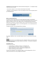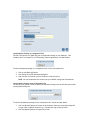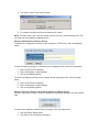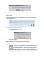
1
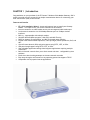
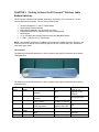
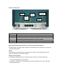
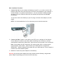
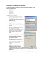
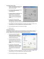
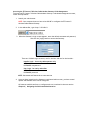
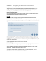
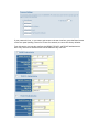
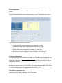
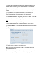
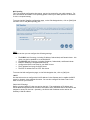
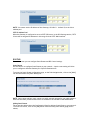
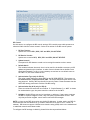
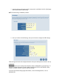
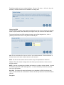
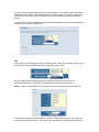
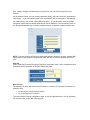
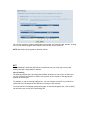
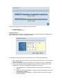
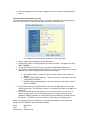
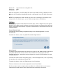
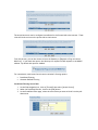
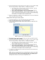
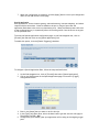
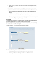
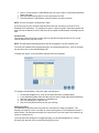
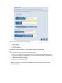
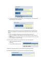
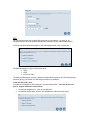
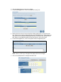
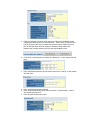
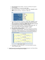
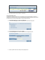
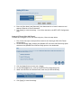
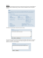
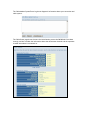
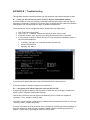
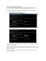
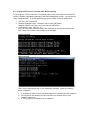
EZ Connect™ Wireless Cable Modem Gateway
Install Guide
SMC8014W-G
Copyright
Information furnished by SMC Networks, Inc. (SMC) is believed to be accurate and reliable.
However, no responsibility is assumed by SMC for its use, nor for any infringements of patents
or other rights of third parties which may result from its use. No license is granted by
implication or otherwise under any patent or patent rights of SMC. SMC reserves the right to
change specifications at any time without notice.
Copyright © 2006 by
SMC Networks, Inc.
38 Tesla
Irvine, California 92618
All rights reserved.
Trademarks
Information furnished by SMC Networks, Inc. (SMC) is believed to be accurate and reliable.
However, no responsibility is assumed by SMC for its use, nor for any infringements of patents
or other rights of third parties which may result from its use. No license is granted by
implication or otherwise under any patent or patent rights of SMC. SMC reserves the right to
change specifications at any time without notice.
TABLE OF CONTENTS
CHAPTER 1 | Introduction
Features and Benefits
Package Contents
Minimum Requirements
CHAPTER 2 | Getting to know the EZ Connect™ Wireless Cable Modem Gateway
LED Indicators
Rear Panel Description
Resetting and Restoring the EZ Connect™ Wireless Cable Modem Gateway
CHAPTER 3 | Installation
Basic Installation Procedure
CHAPTER 4 | Configuring your Computer
Configuring Windows 95/98/Me
Configuring Windows 2000
Configuring Windows XP
Configuring a Macintosh Computer
CHAPTER 5 | Configuring the EZ Connect™ Wireless Cable Modem Gateway
Browser Configuration
Disable Proxy Connection
Accessing the EZ Connect™ Wireless Cable Modem Gateway Web Management
CHAPTER 6 | Navigating the Web-based Administration
Making Configuration Changes
System
WAN
LAN
Routing
Wireless
NAT
Firewall
Tools
VPN
Status
APPENDIX A | Telnet/CLI Information
APPENDIX B | Troubleshooting
APPENDIX C | Technical Specifications
APPENDIX D | Compliances
APPENDIX E | Technical Support
CHAPTER 1 | Introduction
Congratulations on your purchase of the EZ Connect™ Wireless Cable Modem Gateway. SMC is
proud to provide you with a powerful yet simple communication device for connecting your
local area network (LAN) to the Internet.
Features and Benefits
•
•
•
•
•
•
•
•
•
•
•
•
•
•
EZ 3-Click Installation Wizard - A new and improved way to install your Gateway
Modem. In 3 simple clicks, you will be connected to the Internet.
Internet connection to cable modem service via an integrated cable modem port
Local network connection via 10/100 Mbps Ethernet ports or 54 Mbps wireless
interface.
802.11g - interoperable with multiple vendors.
Wireless: WEP and WPA encryption, Hide SSID, and MAC Filtering
DHCP for dynamic IP configuration, and DNS for domain name mapping.
Firewall with Stateful Packet Inspection, client privileges, hacker prevention, DoS, and
NAT.
Virtual Private Network (VPN) end-point support using PPTP, L2TP, or IPSec
VPN pass-through support using PPTP, L2TP, or IPSec
User-definable application sensing tunnel supports applications requiring multiple
connections
Built-in Parental controls allow you to limit certain web sites – configurable by time
and date.
Email alerts when hacking attempts on the users network are made
Easy setup through a web browser on any operating system that supports TCP/IP
Compatible with all popular Internet applications
Package Contents
Before installing the EZ Connect™ Wireless Cable Modem Gateway, verify that you have the
items listed under below. Also be sure that you have the necessary cabling. If any of the items
are missing or damaged, contact your local SMC distributor.
•
•
•
•
•
1 - EZ Connect™ Wireless Cable Modem Gateway
1 - Power adapter (12V/1.25A)
1 - CAT-5 Ethernet cable
1 - USB Cable
Installation CD, including:
o User Guide
o USB Drivers
If possible, retain the carton and original packing materials in case there is a need to return
the product.
Please register your product on SMC’s web site at http://www.smc.com.
System Requirements
You must meet the following minimum requirements:
•
•
•
•
Provisioned Internet access from a cable operator that has approved the SMC8014W-G
A computer equipped with a wired or wireless network adapter with TCP/IP installed.
A Java-enabled web browser, such as Microsoft Internet Explorer 5.5 or above, or
Netscape Communicator 5.0 or above.
Windows 98 Second Edition or higher is required for USB driver support.
CHAPTER 2 | Getting to Know the EZ Connect™ Wireless Cable
Modem Gateway
The EZ Connect™ Wireless Cable Modem Gateway is the perfect all in one solution, for the
home or business environment. This full-featured device has:
•
•
•
•
•
•
•
An approved DOCSIS 1.1 and 2.0 Cable modem
Advanced SPI Firewall Gateway
High-speed 54 Mbps 802.11g Wireless Access Point
Comprehensive LEDs for network status and troubleshooting
Reset Button
4 – 10/100 Mbps Auto-Sensing LAN ports with Auto-MDI MDIX feature
1 – USB 1.1 LAN Port for PC connectivity
NOTE: Cable modems provide up to 38 Mbps downstream and 10 Mbps upstream. However, you
should note that the actual rate provided by specific service providers may vary dramatically
from these upper limits.
LED Indicators
The Gateway includes LED indicators on the front panel that simplify installation and network
troubleshooting.
The Gateway includes LED indicators on the front panel that simplify installation and network
troubleshooting.
LABEL
Power
LED COLOR
Green
ON
FLASHING
Power is supplied to the
Gateway
N/A
Diag
Amber
Cable
Green
Traffic
Green
WLAN
LAN (1-4)
Green
Green
USB
Green
System Failure. Reboot
Gateway
Successfully connected to
cable network
Cable Modem has finished
CMTS registration
Good Wireless Link
Connected at 10 or 100
Mbps
USB port connected
N/A
Attempting to
connect to network
Attempting to
register with CMTS
Data transmitting
Data transmitting
Data transmitting
OFF
Power is not
supplied to the
Gateway
Normal Operation
N/A
N/A
No Wireless Link
No Ethernet link
detected
No USB link detected
Rear Panel Description
Power
LAN
Ports
CATV
Connector
Reset
Button
USB
Item
Power
Reset
LAN 1-4
USB
CATV
Description
Connect the included power adapter to this port.
Use this button to reset the power or restore the default factory settings.
Four 10/100 Auto-sensing switch ports (RJ-45). Connect devices on your local
area network to these ports (such as a PC, hub, or switch).
Connect a USB Cable from your PC to this port.
Connect your cable line to this port.
Rebooting and Restoring the EZ Connect™ Wireless Cable Modem Gateway
The Reset button is located on the rear panel of the Gateway. Use a paper clip or a pencil tip
to push the Reset button.
Reboot
If the Gateway is having problems connecting to the Internet, simply hold down the reset
button for less than 2 seconds then release.
Restore Factory Defaults
If rebooting the Gateway does not resolve your issue, then you can follow these steps:
1. Leave power plugged into the Gateway.
2. Locate the reset button on the back panel, press and hold button for at least 5 seconds.
3. Release reset button.
CHAPTER 3 | Installation
The EZ Connect™ Wireless Cable Modem Gateway can be installed in any location where you
have cable Internet access, and your cable Internet service provider has approved the
Gateway. To confirm you meet these 2 criteria points, please contact your cable operator.
For general installation please follow the guidelines outlined below to best performance:
•
•
•
Keep the Gateway away from any heating devices.
Do not place the Gateway in a dusty or wet environment.
For optimum wireless performance, install the Gateway away from other electronic
devices, such as Monitors / TV / 2.4GHz Cordless Phones. These devices can hamper
your wireless throughput and distance.
Basic Installation Procedure
1. Connect the LAN: You can connect the Gateway to your PC, or to a hub or switch. Run
Ethernet cable from one of the LAN ports on the rear of the Gateway to your computer’s
network adapter or to another network device. You can use either a standard straight
through or cross over Ethernet cable since the Gateway incorporates Auto-MDI MDIX
functionality.
You can also connect the Gateway to your PC (using a wireless client adapter) via radio
signals.
NOTE: It is recommended that for first-time setup you use a wired connection.
2. Connect the WAN: Connect a coax cable to the CATV port on the back of the Gateway
from a cable port located in your home. When connecting to the CATV port, use only
manufactured coaxial patch cables with F-type connectors at both ends for all connections.
Note: If this modem was NOT installed by your cable provider (ISP) or is being used to
replace another cable modem – please contact your Cable Operator to register the
SMC8014W-G. Without registering the modem with your cable operator it will be unable to
connect to the cable network system.
3. Power on: Connect the power adapter to the Gateway.
Warning: Only use the power adapter that was provided with the Gateway, using another
power adapter may damage your unit and void the warranty.
CHAPTER 4 | Configuring your Computer
The information outlined in this chapter will guide you through the configuration for the
following Operating Systems:
•
•
•
•
•
Windows 95/98
Windows Me
Windows 2000
Windows XP
Apple Macintosh
Configuring Windows 95/98/Me
1. Access your Network settings by clicking
[Start], choose [Settings], and then select
[Control Panel].
2. In the Control Panel, locate and double-click
the [Network] icon.
3. Highlight the TCP/IP line that has been
assigned to your network card on the
[Configuration] tab of the [Network]
properties window. (see network dialog box to
the right)
4. Next, click the [Properties] button to view
that adapter’s TCP/IP settings.
5. From the TCP/IP Properties dialog box, click
the [Obtain an IP address automatically]
option. (see TCP/IP dialog box to the
right)
6. Next click on the [Gateway] tab and verify
the Gateway field is blank. If there are IP
addresses listed in the Gateway section,
highlight each one and click [Remove]
until the section is empty.
7. Click the [OK] button to close the TCP/IP
Properties window.
8. On the Network Properties Window, click
the [OK] button to save these new
changes.
NOTE: Windows may ask you for the
original Windows installation disk or
additional files. Check for the files at
c:\windows\options\cabs, or insert your Windows CD-ROM into your CD-ROM drive and
check the correct file location, for example, D:\win98, D:\win9x. (Assume “D” is your
CD-ROM drive).
9. Windows may prompt you to restart the PC. If so, click the [Yes] button. If Windows
does not prompt you to restart your computer, do so anyways to ensure your settings.
Configuring Windows 2000
1. Access your Network settings by clicking
[Start], choose [Settings], and then
select [Control Panel]
2. In the Control Panel, locate and doubleclick the [Network and Dial-up
Connections] icon
3. Locate and double-click the [Local Area
Connection] icon for the Ethernet
adapter that is connected to the
Gateway. When the Status dialog box
window opens, click the [Properties]
button.
4. On the [Local Area Connection]
Properties box, verify the box next to
Internet Protocol (TCP/IP) is checked.
Then highlight the Internet Protocol (TCP/IP), and click the Properties button.
5. Select Obtain an IP address automatically to configure your computer for DHCP. Click
the [OK] button to save this change and close the Properties window.
6. Click the [OK] button again to save these new changes.
7. Reboot your PC.
Configuring Windows XP
The following instructions assume you are running Windows XP with the default interface. If
you are using the Classic interface (where the icons and menus look like previous Windows
versions), please follow the instructions for Windows 2000 outlined above.
1. Access your Network settings by
clicking [Start], choose [Control
Panel], select [Network and Internet
Connections] and then click on the
[Network Connections] icon.
2. Locate and double-click the Local
Area Connection icon for the Ethernet
adapter that is connected to the
Gateway. Next, click the [Properties]
button.
3. On the [Local Area Connection]
Properties box, verify the box next to
Internet Protocol (TCP/IP) is checked.
Then highlight the Internet Protocol
(TCP/IP), and click the Properties
button.
4. Select Obtain an IP address automatically to configure your computer for DHCP. Click
the [OK] button to save this change and close the Properties window.
5. Click the [OK] button again to save these new changes.
6. Reboot your PC.
Configuring a Macintosh Computer
You may find that the instructions here do not exactly match your screen. This is because these
steps and screen shots were created using Mac OS 10.2. Mac OS 7.x and above are all very
similar, but may not be identical to Mac OS 10.2.
1. Pull down the Apple Menu. Click System Preferences and select Network. Make sure
that
2. Built-in Ethernet is selected in the Show field.
3. On the TCP/IP tab, select Using DHCP in the Configure field.
4. Close the TCP/IP dialog box.
CHAPTER 5 | Configuring the EZ Connect™ Wireless Cable Modem
Gateway
After you have configured TCP/IP on a client computer, use a web browser to configure the EZ
Connect™ Wireless Cable Modem Gateway. The Gateway can be configured by any Javasupported browser including Internet Explorer 5.0 or above, or Netscape Navigator 5.0 or
above. Using the web management interface, you can configure the Gateway features and view
its settings.
Before you attempt to log into the Gateway’s Web-based Administration, please verify the
following:
1. Your browser is configured properly. (see below)
2. Disable any firewall or security software that may be running.
3. Confirm that you have a [link] LED where your computer is plugged into the Gateway.
If you don’t have a [link] light, try another cable.
Browser Configuration
Confirm your browser is configured for a direct connection to the Internet using the Ethernet
cable that is installed in the computer. This is configured through the options/preference section
of your browser.
Disable Proxy Connection
You will also need to verify that the “HTTP Proxy” feature of your web browser is disabled. This
is so that your web browser will be able to view the web-based configuration pages. The
following steps are for Internet Explorer and for Netscape. Determine which browser you use and
follow the appropriate steps.
Internet Explorer (5.0 or above)
1. Open Internet Explorer. Click [Tools], and then select [Internet Options].
2. In the [Internet Options] window, click the [Connections] tab.
3. Click the [LAN Settings] button.
4. Clear all the check boxes and click [OK] to save these LAN settings changes.
5. Click [OK] again to close the [Internet Options] window.
NOTE: To ensure proper screen refresh after a command entry, be sure that Internet Explorer
5.0 is configured as follows: Under the menu “Tools/Internet Options/General/Temporary
Internet Files/Settings,” the setting for “Check for newer versions of stored pages” should be
“Every visit to the page.”
Netscape (5.0 or above)
1. Open Netscape. Click [Edit], and then select [Preferences].
2. In the [Preferences] window, under [Category], double-click [Advanced], then select
the [Proxies] option.
3. Check [Direct connection to the Internet].
4. Click the [OK] button to save the changes.
Accessing the EZ Connect™ Wireless Cable Modem Gateway’s Web Management
To access the EZ Connect™ Wireless Cable Modem Gateway’s web-based management screens,
follow the steps below:
1. Launch your web-browser.
NOTE: Your computer does not have to be ONLINE to configure the EZ Connect™
Wireless Cable Modem Gateway.
2. In the Address Bar, type: http://192.168.0.1
3. When the Gateway’s Login screen appears, enter the default username and password,
and click the [Login] button to access the Gateway.
There are 2 default login accounts, one for the User and one for the Installer:
Installer Login – for use by cable operator only
USERNAME: mso
PASSWORD: msopassword
User Login – for use by subscriber
USERNAME: cusadmin
PASSWORD: password
NOTE: Usernames and Passwords are case sensitive
4. Once you have logged into the Gateway’s web-based admin screen, you have several
options and features which can be configured.
All features available and how to configure each one is outlined in the next section
Chapter 6 | Navigating the Web-based Administration.
CHAPTER 6 | Navigating the Web-based Administration
The EZ Connect™ Wireless Cable Modem Gateway’s management interface allows you to
configure both basic and advanced features and options. Some of these advanced functions
include: hacker attack detection, IP and MAC address filtering, intrusion detection, port
forwarding setup, virtual DMZ hosts, as well as other advanced functions.
Making Configuration Changes
Once a configuration change has been made on a page, be sure to click the [Apply] or [Next]
button at the bottom of the page to enable the new setting.
SYSTEM
This section is used to configure the device mode and administration options including
passwords and remote management settings.
To access the System Settings configuration page, on the Side Navigation bar, click on [System]
link.
Selecting the [Disable ALL Commercial Gateway Functions] sets the Gateway to operate as a
bridging cable modem. In this mode all LAN interfaces are enabled including Ethernet, USB,
and Wireless, but all Gateway functions are disabled including Firewall, NAT, DHCP Server, URL
Blocking, and VPN end points.
A Router Name for the Gateway can also be set on this page.
Password Settings
From this section you can configure new passwords for the [mso] and [cusadmin] administrator
accounts.
You can also set the Idle Time Out value that the SMC8014W-G will keep an admin account
logged in for. The default Idle Time Out value is 10 min.
To access the Password Settings configuration page, on the Side Navigation bar, click on
[System] link and then click on the [Password Settings] link.
If your password is lost, or you cannot gain access to the user interface, press the Reset button
on the rear panel (holding it down for at least five seconds) to restore the factory defaults.
From this section you can also configure the RADIUS, TACACS+ and TACACS authentication.
Note: only one form of authentication can be enabled at any one time.
Remote Management
Allows a remote PC to configure, manage, and monitor the Gateway using a standard web
browser.
To access the Remote Management configuration page, on the Side Navigation bar, click on
[System] link and then click on the [Remote Management] link.
This feature has several options to configure:
•
•
•
•
•
•
Configure the HTTP remote management port (default port: 8080)
Configure the Telnet remote management port (default port: 2323)
Configure the HTTPS remote management port (default port: 8181)
Specify if MSO remote management is allowed (i.e. “mso” login)
Specify if Customer remote management is allowed (i.e. “cusadmin” login)
Customize the remote management access list (default: All IP addresses)
HTTP Remote Management
The default setting for this is enabled on port 8080. To access the remote management web
page you would access it at http://xxx.xxx.xxx.xxx:8080 (where xxx.xxx.xxx.xxx is your WAN IP
listed on the status page). If you change the port to another setting then simply change the
information in the URL.
NOTE: Do not set the remote management port to use a port that is already in use by the
gateway or PC on the private LAN. For example, if a remotely accessible WEB or FTP server is
running on the private LAN (i.e. a Port Forwarding rule has already been created for this
service) you cannot set the remote management port to 80, 20, or 21.
Telnet Remote Management Port
The default setting for this is disabled on port 2323. Telnet enables access to the Command
Line Interface (CLI). Refer to Appendix A for CLI commands.
Enable Customer Remote Management
This feature enables the customer to remotely access the web-based administration screen
with their username and password (default: cusadmin/password). To enable this feature,
check the [Customer Remote Management] checkbox.
Remote Management Access Rule
This option will allow you to limit who can access the remote management web login from the
Internet.
The [Everyone] option allows any Internet user to access the web management login.
The [IP address range] option allows you to set a range of public Internet IP addresses. You can
access the web management login from any IP address in the specified range.
The [Single Address] option allows you to set just 1 public Internet IP address. This is the ONLY
IP address that you access the web management login screen.
A combination of one or more IP address ranges and single addresses can be configured.
WAN
From this section you can configure all the WAN Settings.
To access the WAN configuration page, on the Side Navigation bar, click on [WAN] link.
You can setup the SMC8014W-G to support the Pubic LAN IP as the WAN IP by selecting the [Use
public LAN IP as the WAN IP] checkbox. The Public LAN IP can be configured in the LAN
Settings section.
Click the DHCP WAN IP [Release/Renew] button to release and renew the WAN IP address.
DNS Settings
You can also configure the Gateway to use custom DNS servers.
NOTE: DNS is short for Domain Name System. The DNS IP is a server that that translates
domain names into IP addresses.
Host Name
The Host Name setting is an optional configuration and is used when required by your cable
operator. Contact your cable operator to determine if this setting is required.
MAC Spoofing
This is an optional configuration that may or may not be required by your cable operator. For
more information about MAC Clone/Spoofing please contact your cable operator to determine
if this is a required setting.
To access the MAC Spoofing configuration page, on the Side Navigation bar, click on [WAN] link
and then click on the [MAC Spoofing] link.
LAN
From this section you can configure the following settings:
•
•
•
•
•
•
The PUBLIC LAN IP settings, including IP Address, Subnet Mask, and Domain Name – this
option can also be enabled to act as the WAN IP.
The PRIVATE LAN IP settings, including IP Address, Subnet Mask, and Domain Name.
Enable or Disable the integrated DHCP server
Configure the DHCP Lease time for your DHCP clients
The IP Address Pool range for DHCP clients
The PPTP IP Address Pool for PPTP VPN clients
To access the LAN configuration page, on the Side Navigation bar, click on [LAN] link.
LAN IP
Use the LAN section to configure the LAN IP address for the Gateway and to enable the DHCP
server for dynamic client address allocation. You can also configure the Lease Time for the
DHCP clients on your network.
Public LAN IP Settings
Define a range of public IPs that are used on the LAN. The combination of IP address and
Subnet Mask settings determine the Public LAN subnet and IP addresses within this network are
assigned to servers on the LAN. Optionally, the Public LAN IP address can be used as the
Gateway’s WAN IP address.
Private LAN IP Settings
Define the Gateway’s private LAN settings. The IP address configured here is the Gateway’s
(default: 192.168.0.1).
NOTE: Port Forwarding and Access Control rules will be based on the network scope defined
here. If either of these types of rules were previously setup and the Private LAN IP address is
changed, then those rules will need to be recreated to reflect the new Private LAN IP network.
DHCP Server Settings
The Gateway’s DHCP Server can be turned enabled/disabled here. Also the DHCP client Lease
Time can be adjusted from the default One Week setting. The Gateway functions as a DNS
proxy by default. DNS proxy can be disabled by configuring Primary and Secondary DNS values
here, which LAN DHCP clients will receive in their lease.
Private IP Address Pool
The scope of LAN DHCP IP addresses that the Gateway will assign to clients is 192.168.0.10 to
192.168.0.59 by default. IP addresses from 192.168.0.2 to 192.168.0.9 and from 192.168.0.230
to 192.168.0.254 are available for static IP address assignments.
NOTE: You cannot use the IP address of the Gateway (192.168.0.1 – default IP) in the client
address pool.
PPTP IP Address Pool
When the Gateway is configured to act as a PPTP VPN server in the VPN Settings section, PPTP
clients will be assigned IP addresses in this range for their PPTP WAN interface.
ROUTING
From this section you can configure Static Routes and RIP Control settings.
Static Routes
Use this section to configure Static Routes on your network. A static route setting will allow
you to configure a different Gateway for a Specific Destination IP.
To access the Static Routes configuration page, on the Side Navigation bar, click on the [WAN]
link and then select the [Static Route] link.
NOTE: Users cannot add any static routes to a public network assigned by your cable operator.
Users can add other private networks that are located on the LAN side of the SMC8014W-G.
Adding Static Routes
The screen shot below shows the Configuration Page for adding a Static Route to your network.
To access this screen, click on the [Add] button from the main [Static Routes] page (shown
above).
RIP Control
Use this section to configure the RIP control settings. RIP is used by some cable operators to
advertise Public LAN IPs to their network. Below is an outline of the RIP control options:
1. RIP Send Version:
Options are to send RIP1| RIP2| RIP1 and RIP2| DO NOT SEND.
2. RIP Receive Version:
Options are to receive RIP1| RIP2| RIP1 and RIP2| DO NOT RECEIVE.
3. Update Interval:
Time period for RIP daemon to send out its routing information to other routers.
4. Default Metric:
This variable indicates the metric that is to be used for the default route entry in RIP
updates originated on this interface. A value of zero indicates that no default route
should be originated. For CM, it is not necessary to send out its own default route to
the CMTS. So, this value should be zero.
5. Authentication Type (only for RIPv2):
This value is used when users choose RIP2 for the RIP SEND/RECEIVE. The options are
No authentication| Simple Password| MD5. The Simple Password option uses a clear
text password. Usually, MD5 is preferred for security reason. Please be aware that the
CMTS's RIP setting must match with the CM's RIP setting.
6. Authentication Key & ID (only for RIPv2):
These two values are used with item 5 above. If “Simple Password” or “MD5” is chosen
for authentication type, they must match the values set in the CMTS.
7. Neighbor: Usually RIP are sent out by broadcast or multicast. If users want to unicast
the RIP to a specific neighbor router, they can specify the destination IP here. Then
only that particular neighbor router would receive the RIP messages.
NOTE: It is best to use RIP2 when using non-classful IP addresses. In other words, use RIP2 for
those networks that are subneted (e.g. a subnet mask other than 255.0.0.0 for a Class A IP
address). RIP1 does not support classless inter-domain routing (CIDR) which is the method used
to subdivide networks with subnet masks.
To configure the RIP settings via Web UI, please follow the steps outlined below:
1. You will need to confirm the network is setup with a valid Public LAN IP in [LAN] page
before they enable the RIP setting.
NOTE: The RIP setting is disabled by default.
2. After you confirm the LAN Settings, then you will need to configure the RIP Settings.
These settings will need to be configured based on how your cable operator network is set up.
WIRELESS
This section allows you to configure the Gateway’s built-in 54 Mbps 802.11g Access Point. To
setup the wireless connections, you will need to do define the Service Set Identifier (SSID),
Channel, Encryption options, and other optional settings.
To access the Wireless Settings page shown below, on the Side Navigation bar, click on
[Wireless] link.
The Wireless Mode can be set to Mixed (default), 11B only, 11B+ only, or 11G only. Also, the
Gateway’s wireless interface can be disabled if not being used.
Channel and SSID
You must specify a common radio channel and SSID (Service Set ID) to be used by the Gateway
and all of your wireless clients. Be sure you configure all of your clients to the same values.
To access the Channel and SSID configuration page, on the Side Navigation bar, click on
[Wireless] link and then click on the [Channel and SSID] link.
SSID: This is the Wireless ID or Service Set ID of your wireless network. This should be set to
the same value as the other wireless devices in your network.
NOTE: The SSID is case sensitive and can consist of up to 32 alphanumeric characters.
Channel: The radio channel through which the Gateway communicates to clients over the
wireless network.
NOTE: If you are not getting good wireless performance try another wireless channel – because
this Gateway operates in the 2.4GHz spectrum – it can be affected by some other products,
such as cordless phones.
Hide SSID: This option will cause the Gateway to not broadcast its SSID. By selecting this
option, wireless clients will not be able to use their Site Survey feature to locate this wireless
network.
Encryption
If you are transmitting sensitive data across wireless channels, you should enable either Wired
Equivalent Privacy (WEP) or WiFi Protected Access (WPA) encryption. Encryption requires you
to use the same set of encryption/decryption keys for the Gateway and all of your wireless
clients.
To access the Encryption configuration page, on the Side Navigation bar, click on [Wireless] link
and then click on the [Encryption] link.
WEP
Select [WEP] from the [Encryption Type] drop down menu. Select the Automatic, Open System,
or Shared Key from the [WEP Authentication Type] drop down menu.
You can choose between standard 64-bit or 128-bit encryption keys. Below are the
configuration options for 64-bit WEP. A passphrase or a manual key can be used.
NOTE: To enter a manual WEP key you will need to enter hexadecimal values (A-F and 0-9).
To automatically generate a 64-bit WEP key, enter in a Passphrase (keyword - ex. Home) and
click the [Generate Keys] option. Once you do this, the Gateway will dynamically generate 4
keys. Simply configure the Default Key to the one key that you will be using across your
network.
On the wireless clients, you can use the passphrase option, and client utility will generate the
same 4 keys – or you can manually type in the selected KEY that is configured on the Gateway.
For more security, you can use 128-bit WEP encryption. To use this mode, click the [128 Bit
Encryption] option and the configuration section will be displayed. You can manually enter in
the 26-digit hexadecimal key or use the passphrase option to generate random dynamic keys.
NOTE: If you are having a difficult time getting the wireless connection up after enabling WEP –
please confirm that you have configured the SAME WEP key on both the Gateway and Client
card.
WPA-PSK
Select [WPA-PSK] from the [Encryption Type] drop down menu. Next, enter a passphrase value
between 8 and 63 characters in the [WPA Passphrase] field.
MAC Filtering
The Gateway can allow the wireless client stations to connect over a wireless connection in 2
different ways:
1. By allowing all wireless stations access;
2. Or by allowing only Trusted PCs.
To access the MAC Filtering configuration page, on the Side Navigation bar, click on [Wireless]
link and then click on the [MAC Filtering] link.
You can also configure a [Device Name] that is associated with a specific MAC address. In doing
this, you can easily recognize the computers that you are in your access list.
NOTE: MAC filtering only applies to Wireless Clients.
NAT
Network Address Translation (NAT) allows multiple users at your local site to access the
Internet through a single public IP address.
Port Forwarding
The Gateway supports port forwarding that enables customers to host servers on their LAN.
You can configure this feature to redirect the external service request to the appropriate
internal server and port.
For example, if you are running a WEB server, you can configure all traffic on port 80 to be
redirected to the IP address of the WEB server running on your network.
To access the Port Forwarding configuration page, on the Side Navigation bar, click on [NAT]
link and then click on the [Port Forwarding] link.
This Port Forwarding function supports 2 types of Services:
•
•
Predefined Service
Customer Defined Service
Predefined Service
The Predefined Service option has a pull-down menu with several popular Service Applications,
such as HTTP (80), FTP (20/21), and AIM/ICQ (5190).
To configure Port Forwarding with a Predefined Service rule, follow the steps below:
1. Select the [Service] that you want to have access through the firewall to your LAN from
the pull-down menu.
2. Enter in the [LAN Server IP] for the LAN PC that is running this service or application
3. You can also configure [Remote IPs] option to allow access to this specific port from
the WAN side. This can be configured for 3 different access types:
a. Any IP Address [Any] – choose this option to allow access from any public IP
address.
b. Single IP Address [Single Address] – choose this option to only allow access from
a single public IP address.
c. IP Address Range [Address Range] – choose the option to only allow a range of
public IP addresses.
4. Click the [Apply] button to save your changes and return to the Port Forwarding main
screen
Customer Defined Service Rule (Custom)
The Customer Defined Service section allows you to custom configure a Port Forwarding rule
with any Traffic type (TCP/UDP/TCP and UDP), Public Port, and Private Port.
To configure this custom option, please follow the steps below:
1. Enter in a Description [Name] for this custom setting
2. Configure the Traffic or Data [Type] that you want to forward. The options are TCP |
UDP | TCP/UDP.
3. Set the [LAN Server IP] of the PC that you want this traffic/data redirected to
4. You can also configure [Remote IPs] option to limit access to this specific port from the
WAN side. This can be configured for 3 different access types:
a. Any IP Address [Any] – choose this option to allow access from any public IP
address.
b. Single IP Address [Single Address] – choose this option to only allow access from
a single public IP address.
c. IP Address Range [Address Range] – choose the option to only allow a range of
public IP addresses.
5. Set the [Start Public Port] and [End Public Port] that this application will use on the
WAN (Internet) side. The Gateway will listen for incoming traffic/data to its WAN IP on
these ports.
6. Set the [Private Ports] that the Gateway will forward this traffic to on the LAN. If
there is a range of ports, enter the starting private port in [Private Ports], select
[Enable Port Range] checkbox, and the Gateway will automatically calculate the end
private port. The LAN PC server will listen for traffic/data on this/these ports.
Below is an example setting for a WEB server on an Internet connection, where port 80 is
blocked from the WAN side, but port 8000 is available.
Name:
Web Server
Type:
TCP
LAN Server IP: 192.168.0.100
Remote IPs:
Public Port:
Private Port:
Any (allow access to any public IP)
8000
80
With this configuration, all HTTP (Web) TCP traffic on port 8000 from any IP Address from the
WAN side will be redirected through the firewall to the Internal Server (192.168.0.100) on port
80.
NOTE: This configuration is useful because you don’t have to reconfigure your web server to
accept traffic on a different port, you can do this configuration on the Gateway.
FIREWALL
The Gateway provides a stateful inspection firewall (SPI), which is designed to protect against
Denial of Service (DoS) attacks. Its purpose is to allow a private local area network (LAN) to be
securely connected to the Internet. To provide a flexible solution, the firewall section has the
following features:
Firewall Enable/Disable
To access the Security Settings configuration page, on the Side Navigation bar, click on
[Firewall] link.
To enable this feature, check the [Enable Firewall Module] checkbox.
Access Control
The Access Control section allows the setting of two types of rules: enable access to services on
your public LAN network from the Internet or to block services on the private LAN from
accessing the Internet. Access Rules can be configured to a specific LAN IP Address or a range
of LAN IP Address’s.
To access the Access Control configuration page, on the Side Navigation bar, click on [Firewall]
link and then click on the [Access Control] link.
To enable this feature, check the [Enable Access Control] checkbox.
There are 2 sections in that can be configured for Access Control Rules.
The first section is used to configure the Access Rules for the Public LAN from the Internet.
These rules will enable services on the public LAN to be accessed by the Internet.
The second section is used to configure Access Rules for the Private LAN to the Internet. These
rules will block services on the private LAN to the Internet.
From this section, you can also choose to have the Gateway to [Respond to Ping on Internet
WAN Port]. If you check this option, the Gateway will respond to PING requests to the WAN IP
address. By default this option is enabled.
For convenience, each Access Control section includes 2 filtering options:
•
•
Predefined Filtering
Customer Defined Filtering
Predefined Filtering Access Rule:
1. On the Side Navigation bar, click on [Firewall] then select [Access Control]
2. Under the Predefined Section, click on the [Add] button
3. On the Predefined Filter page, select the service that you want to block from the pulldown menu
4. Select the [LAN IPs] that you want this access rule to apply to. You can choose to apply
this rule to Any IP Address, a Single IP Address, or a Range of IP Addresses.
a. Any IP Address [Any] – choose this option to block all LAN clients. You don’t
need to configure the [Start IP] or [End IP] options.
b. Single IP Address [Single address] – choose this option to block a single LAN
client. Enter the LAN IP address of the PC in the [Start IP] field.
c. IP Address Range [Address Range] – choose this option to block a range of LAN
clients. Enter the starting LAN IP address in the [Start IP] field and the ending
LAN IP address of the range you want in the [End IP] field.
5. When your configuration is complete, click the [Apply] button to save your changes and
return to the main Access Control page.
Customer Defined Filtering Access Rule (Custom):
1. On the Side Navigation bar, click on [Firewall] then select [Access Control]
2. Under the Customer Defined Section, click on the [Add] button
3. On the Customer Defined Filter page, define a Name for the service/application that
you want to block.
NOTE: The Name is only for reference purposes.
4. Then select the protocol type from the pull-down menu that they would like to block.
The options are TCP | UDP | TCP/UDP.
5. Select the [LAN IPs] that you want this access rule to apply to. You can choose to apply
this rule to Any IP Address, a Single IP Address, or a Range of IP Addresses.
a. Any IP Address [Any] – choose this option to block all LAN clients. You don’t
need to configure the [Start IP] or [End IP] options.
b. Single IP Address [Single address] – choose this option to block a single LAN
client. Enter the LAN IP address of the PC in the [Start IP] field.
c. IP Address Range [Address Range] – choose this option to block a range of LAN
clients. Enter the starting LAN IP address in the [Start IP] field and the ending
LAN IP address of the range you want in the [End IP] field.
6. To complete the configuration enter in the [From Port] and [To Port] information will
be blocked on the network.
NOTE: Usually every application has its own corresponding port number. Users should
find out the correct port number from the application vendor. For example, if you are
trying to block access to a Peer-2-Peer file sharing application then you should visit
that applications web site to see the ports that application uses.
7. When your configuration is complete, click the [Apply] button to save your changes and
return to the main Access Control page.
Special Application
Some applications, such as Internet gaming, videoconferencing, Internet telephony, and others
require multiple connections. Rules are based on the port or range of ports that the
application sends data to the server on (destination port). When the Gateway sees traffic sent
to the configured port(s), it dynamically allows all incoming traffic from the server on any port
for the specified time.
To access the Special Application configuration page, on the Side Navigation bar, click on
[Firewall] link and then click on the [Special Application] link.
To enable this option, click the [Enable Triggering] checkbox.
To configure a Special Application Rule, follow the steps outlined below:
1. On the Side Navigation bar, click on [Firewall] then select [Special Application]
2. Click on the [Add] button on the Special Application page to access the [Trigger]
configuration section.
3. Enter in the [Name] that you want to use for this rule.
4. In the [Type] pull-down menu, select the data/traffic type that this rule will apply to.
The options are TCP | UDP.
5. Configure the [Port Number] that your application will be using as the outgoing trigger
ports.
6. Set the [Interval] of the rule. This is the time in between the outgoing and incoming
data traffic.
NOTE: If you set this value too low, the incoming ports will be closed before the return
data arrives at the firewall and the connection will be broken and the application will not
work.
7. The last 2 options are for Advanced Users, most users can leave this at the default
settings:
•
•
IR Replacement – Default Setting: Disable address replacement
Allow sessions initiated from/to the 3rd host – Default Setting: unchecked
8. When your configuration is complete, click the [Apply] button to save your changes and
return to the main Special Application page.
URL Blocking
This section allows you to control the content network. This feature is good for both business
and parents looking to control the content accessible from a web browser.
To access the URL Blocking configuration page, on the Side Navigation bar, click on [Firewall]
link and then click on the [URL Blocking] link.
To enable this option, click the [Enable Keyword Blocking] checkbox
To configure URL blocking, follow the steps outlined below:
1. On the Side Navigation bar, click on [Firewall] then select [URL Blocking]
2. Check the [Enable Keyword Blocking] checkbox to turn URL blocking on.
3. Enter in a new keyword or URL address that you want to block in the [Keyword/Domain
Name] input box.
4. Press the [Add Keyword] button to save this keyword or URL.
5. The new keyword or URL address would be listed in the text box below.
NOTE: This list will support 50 Keywords or URLs.
If you want a PC on your network to bypass these rules you will need to set that PC as an
Exempted PC/Trusted Host. To configure this option, check the [Add Trusted Host] option and
enter the LAN IP address of the PC that you want to bypass the URL/Keyword blocking function
with.
Schedule Rule
This feature will block Internet content based on the URL blocking function for PCs on your
network based on the day and or time.
NOTE: The URL/Keyword blocking feature must be configured to use this schedule rule.
To access the Schedule Rule configuration page, on the Side Navigation bar, click on [Firewall]
link and then click on the [Schedule Rule] link.
To enable this option, click the [Enable Schedule Function] checkbox.
To configure Schedule Rules, follow the steps outlined below:
1.
2.
3.
4.
5.
On the Side Navigation bar, click on [Firewall] then select [Schedule Rule]
In the [Week Day] table check the Days that you want to apply URL/Keyword Blocking.
Define the appropriate settings for a schedule rule.
Click the [OK] button to approve rule.
Then click the [APPLY] button to save your settings.
Email/Syslog Alert
The Gateway can provide network log and alert information to keep you updated. The
Gateway can send an e-mail to as many as 4 users alerting them of an attempted intrusion or
hacker attack. The Gateway also supports a Syslog Client so you can export your Network Log
entries to a Syslog Server.
To access the Email/Syslog Alert configuration page, on the Side Navigation bar, click on
[Firewall] link and then click on the [Email/Syslog Alert] link.
There are 3 sections to configure on this page:
•
•
•
Email Alerting
Syslog Alerting
Alerting Schedule
To enable the Email Alert feature, click the [Enable Email Alerting] checkbox.
Follow the steps below to configure the Email Alert feature:
1. Enter in your SMTP Server Address (this is also referred to as the outgoing mail server)
2. Enter in the [Sender’s E-mail Address] – this is the email address that is associated with
the outgoing mail server account.
3. Enter in your email [User Name].
4. Enter in your email [Password].
NOTE: If you don’t have your SMTP or outgoing mail server information, please contact
your cable operator.
5. To add an email address to the Alert List, click the [Add] button. The configuration
page shown below will be displayed:
NOTE: The email alert feature will allow you to send email alerts to 4 different email
accounts. For example you could send an email to your home, work, and school email
address.
6. Enter in the [Name] of the person/account that you want to send this to
7. Enter in the [Recipient’s Email Address] as the email address you want to send the
alert to
8. When complete, click the [Apply] button to save your settings and return to the main
Email/Syslog Alert configuration page
If you need to edit or delete an existing email account, follow the steps below
1. Check the radio button next to the
email entry
2. Click the [Edit] or [Delete] button.
To enable the Syslog Alert feature, click the [Enable Syslog Alerting] checkbox.
To configure the Syslog Server, enter the LAN IP of the [Syslog Server Address].
Immediate Alerts can be generated for both the email and Syslog alerts. To configure the type
of Alert that you want to get:
- An Intrusion is detected – this is a hacker attack attempt from the WAN
- Attempts to access a blocked site – alert to any attempts to access a site or keyword listed in
your URL/Blocking list.
DMZ Host (Demilitarized Zone)
If you have a client PC that cannot run an Internet application properly from behind the
firewall, then you can open the client up to unrestricted two-way Internet access. Enter the IP
address of a DMZ host to this screen. Adding a client to the DMZ (Demilitarized Zone) may
expose your local network to a variety of security risks, so only use this option as a last resort.
To access the DMZ configuration page, on the Side Navigation bar, click on [Firewall] link and
then click on the [DMZ] link.
To enable this option, click the [Enable DMZ Host] checkbox.
To configure a DMZ host, Enter in the LAN IP Address of the PC on your network in the input
fields.
TOOLS
The Tools menu allows a user to Backup the current configuration, Restore a previously saved
configuration, Restore factory settings, and Reboot the Gateway. The Gateway configuration
file is a clear text format.
Configuration Tools
From this section you can:
•
•
•
•
Locally backup your Gateway’s settings to a configuration file
Remotely backup your Gateway’s settings to a configuration file
Restore settings from a local or remotely stored configuration file
Restore the Gateway to Factory Defaults
To access the Configuration Tools configuration page, on the Side Navigation bar, click on
[Tools] link and then click on the [Configuration Tools] link.
Locally Backup Settings to Configuration File
The first Tools option is to [Back Up] your configuration settings of your Gateway. This
includes, but is not limited to, Port Forwarding, Special Application, and Alert Emails.
To save the Gateway settings to a configuration file, follow the steps below:
1. Click on the [Back Up] button
2. Click [Save] on the File Download dialog box
3. Save this file to a location on your network or local hard drive.
NOTE: You can rename the file as need, but you CANNOT change the file extension.
Locally Restore Settings from Configuration File
The second Tools option is used to restore the Gateway settings from the file that you backed
up using the Back Up tool.
To restore the Gateway settings from a configuration file, follow the steps below:
1. Click the [Browse] button to browse to the directory where you saved the backup file
or type in the complete location (e.g. C:\backup\smc.cfg) in the input box
2. Click the [Restore] button to begin the process.
3. Click [OK] to confirm the restore process
4. To complete the Restore process the Gateway will reboot.
NOTE: This file format (.cfg) is the only format that you can use to restore settings from. This
is format that is provided by the Backup option.
Remotely Backup/Restore Gateway Settings
To backup your configuration settings of your Gateway to a TFTP server, select the [Backup]
option.
To save the Gateway settings to a remotely stored configuration file, follow the steps below:
1. Enter the [TFTP Server Address]
2. Enter the [Gateway Config Filename]
3. Click on the [Backup] button
To restore the Gateway settings from a remotely stored configuration file, follow the steps
below:
4. Enter the [TFTP Server Address]
5. Enter the [Gateway Config Filename]
6. Click on the [Restore] button
Restore EZ Connect™ Wireless Cable Modem Gateway to Default Settings.
The third Tools option is used to restore to Gateway to the default settings of the last software
load.
To restore your Gateway to Default Factory Settings, follow the steps below:
1. Click the [Factor Reset] button
2. Click [OK] on the confirmation dialog box
3. To complete the Restore process the Gateway will reboot.
Reboot
In the event that the system stops responding correctly or functioning properly, you can
perform a reboot.
To access the Reboot option page, on the Side Navigation bar, click on [Tools] link and then
click on the [Reboot] link.
To reboot the Gateway, follow the steps below:
1. Click the [Apply] button
2. Click [OK] on the confirmation dialog box
3. The Gateway will reboot.
NOTE: The Reboot will be complete when the power LED stops blinking.
Diagnostics
This section can be used to troubleshoot connection and setup issues. You can do the following:
•
•
•
Trace Route – enter in the IP/Domain Name and click [tracert] to begin the trace from
the Gateway.
Ping – enter in the IP/Domain Name and click the [ping] button to begin the ping from
the Gateway.
Send Inspected Traffic to Log Server – enter in the IP Address of your log server and
the amount of time you want to inspect and then click the [Apply] button. The
Gateway will then capture all the data frames seen by the cable modem interface and
send the results to the configured log server.
VPN
The VPN section allows you to setup VPN end points on the Gateway. By doing so, an
encrypted tunnel will be established between the Gateway and the remote VPN end point.
To access the VPN configuration page, on the Side Navigation bar, click on [VPN] link.
The Gateway supports 3 types of VPN termination:
• IPSec
• PPTP
• L2TP over IPSec
To enable a VPN end point protocol, deselect the appropriate option on the VPN settings page
and click [Apply]. By default, all VPN end point options are disabled.
Create an IPSec VPN Tunnel
To enable and configure an IPSec end point, follow the steps below. Ensure that each end
point is assigned a different LAN IP Subnet.
1. On the Side Navigation bar, click on the [VPN] link
2. On the VPN settings page, deselect the [Disable IPsec VPN Functions] option
3. Click the [Apply] button to save your changes
4. On the Side Navigation bar, click on the [Access Control] link
5. Enable LAN clients that will access the IPSec VPN by adding them to the VPN Access
List. There are two ways to add a LAN client to the VPN Access List. Either select the
radio button next to an [Auto-Learned CPE Device] or manually enter the LAN clients
MAC address in the [Manually-Added CPE Devices] section, then select [Add]
6. On the Side Navigation bar, click on the [IPsec Tunnel Configuration] link
NOTE: There is a VPN Log on this page that displays VPN event messages.
7. Click on the [Add] button to configure the IPSec VPN
a. Either the Gateway’s Private LAN IP address or Public LAN IP address can be
configured as the end point for the VPN tunnel. Select either [Protect Private
Lan] or [Protect Public Lan] to enable the entire Private or Public LAN to be
part of the VPN tunnel and the respective Gateway LAN IP address will
populate the [Intranet Address] and [Intranet Subnet Mask] fields.
b. Enter the [Local ID] which must match the “Remote ID” of the remote VPN end
point.
c. Enter the [Remote Gateway ID] which must match the “Local ID” of the remote
VPN end point.
d. Enter the [Remote Gateway Address]
e. Enter the [Pre-shared Key] which must match the “Pre-shared Key” value of
the remote VPN end point.
f. Enter the [IKE Life Duration] value
g. Enter the [Authentication method]. Currently, the Gateway only supports
[Preshared Key].
h. Enter the [IKE HASH]. The options are MD5 | SHA.
i. Enter the [IKE Encryption]. The options are DES | IDEA | BLOWFISH | RC5 |
3DES.
j. Enter the [IPSec Operation]. The options are ESP | AH.
k. Enter the [ESP Transform]. The options are DES | IDEA | BLOWFISH | RC5 |
3DES. This option is only available when ESP [IPSec Operation] is selected.
l. Enter the [ESP AUTH]. The options are NONE | MD5 | SHA | DES. This option
is only available when ESP [IPSec Operation] is selected.
m. Enter the [AH] encryption method. The options are MD5 | SHA | DES. This
option is only available when AH [IPSec Operation] is selected.
n. Enter the [Tunnel Type]. The options are Public | Private.
o. Enter the [IPSec Life Duration] value.
p. Configure the remote VPN end point LAN network address(es) in the Tunnel
Host Remote Configuration section. Select either [IP Subnet] and enter the
remote network address [IP Address] (e.g. 10.0.0.0) and [Subnet Mask] (e.g.
255.255.255.0) or select [IP Range] and enter [Starting IP] and [Ending IP].
q. Click [Apply] to save the configuration. You will be returned to the IPSec
Tunnel Configuration page.
8. Establish the tunnel in the IPSec Tunnel Configuration page by: in the [Tunnel Table],
under [Active Type], select [Negotiate] then [Apply].
9. The [Status] should now be [Phase 2 Completed].
Create a PPTP VPN Tunnel
To enable and configure a PPTP server on the Gateway, follow the steps below. Note that
remote PPTP clients that connect into the Gateway will be assigned IP addresses from the PPTP
IP Address Pool on the LAN Settings page for their PPTP WAN interface.
1. On the Side Navigation bar, click on the [VPN] link
2. On the VPN settings page, deselect the [Disable PPTP VPN Functions] option
3. Click the [Apply] button to save your changes
4. On the Side Navigation bar, click on the [PPTP/L2TP Configuration] link
5. Under the [PPTP/L2TP User Table] click the [Add] button.
6. Enter the [User Name] and [Password]. User Name must be at least 3 characters and
password must be at least 6 characters.
7. Click [Apply] to save the settings. You will be returned to the PPTP/L2TP Configuration
page.
Create a L2TP over IPSec VPN Tunnel
To enable and configure a L2TP over IPSec end point, follow the steps below.
1. First, follow the steps to setup an IPSec tunnel in the Creating an IPSec VPN Tunnel
section above.
2. On the VPN settings page, deselect the [Disable L2TP over IPsec VPN Functions] option
and ensure the [Disable IPsec VPN Functions] option is also deselected.
3. Click the [Apply] button to save your changes
4. On the Side Navigation bar, click on the [PPTP/L2TP Configuration] link
5. Under the L2TP/IPsec Pre-Shared Phrase, enter the [Pre-Shared Phrase]
6. Click [Apply] to save the settings.
STATUS
The Status screen summarizes important information about the Gateway including WAN/LAN
connection status, Wireless settings, software version and hardware versions, and uptime
statistics.
The Network Log shows both firewall and network activity
The LAN Client Log shows the clients connected to the Gateway and the type of connection
(Ethernet or Wireless). This also shows the IP address assigned to the client and the MAC
Address of the client’s network adapter.
The Cable Modem System Event Log shows diagnostic information about your connection and
cable system.
The Cable Status page shows the users the initialization process the SMC8014W-G has been
through, and also includes the information about the downstream channel and the upstream
channel the modem is connected on.
APPENDIX A | Telnet and SSH CLI Commands
Refer to the Remote Management section in Chapter 6 to enable and configure Telnet and
SSH settings.
Refer to the 8014 CLI document for command specifics.
To remotely access the CLI of the SMC8014W-G via Telnet, open a DOS/Command Prompt
and type: telnet IP remote mgmt port Enter
•
•
•
•
•
NOTE: Telnet remote management is not enabled by default. To enable, first log into
the Gateway via the HTTP web admin page and go to System/Remote Management and
select the check box next to Telnet Port
For example, open a command prompt and type: telnet xxx.xxx.xxx.xxx 2323 Enter
(where xxx.xxx.xxx.xxx is your WAN IP listed on the status page)
Enter the same user and password as used for the GUI/HTTP
Commands are case sensitive
Type help and then Enter for a list of commands
Use an SSH client of your choice for SSH remote management.
APPENDIX B | Troubleshooting
This appendix describes common problems you may encounter and possible solutions to them.
B.1 | Verify you are connected to the EZ Connect™ Wireless Cable Modem Gateway
If you are unable to access the Gateway’s web-based administration pages, then you may not
be properly connected or configured. The screen shots in this section were taken on a Windows
2000 machine, but the same steps will apply to Windows 95/98/Me/XP.
To determine your TCP/IP configuration status, please follow the steps below:
1.
2.
3.
4.
Click [Start] then choose [Run]
Type “cmd” or “command” (without the quotes) to open a DOS prompt.
In the DOS window, type “ipconfig” and verify the information that is displayed.
If you computer is setup for DHCP, then your TCP/IP configuration should be similar to
the information displayed:
•
•
•
IP Address: 192.168.0.X (x is number between 100 and 199)
Subnet: 255.255.255.0
Gateway: 192.168.0.1
If you have an IP address that starts with 169.254.XXX.XXX then see section A.2.
If you have another IP address configured, see section A.3.
B.2 | I am getting an IP Address that starts with 169.254.XXX.XXX
If you are getting this IP Address, then you need to check that you are properly connected to
the EZ Connect™ Wireless Cable Modem Gateway.
Confirm that you have a good link light on the Gateway’s port to which this computer is
connected. If not, please try another cable.
If you have a good link light, please open up a DOS window as described in section A.1 and type
“ipconfig /renew” (without the quotes)
If you are still unable to get an IP Address from the Gateway, reinstall your network adapter. If
anti-virus software is running on your computer, disable it before reinstalling the network
adapter. Please refer to your adapter manual for instructions.
B.3 | I have another IP Address displayed
If you have another IP address listed, then the PC may not be configured for a DHCP
connection. Please refer to Chapter 4 | Configure your Computer for information.
Once you have confirmed your computer is configured for DHCP, follow the steps below.
1. Open a DOS window as described above.
2. Type “ipconfig /release” (without the quotes)
3. Then type “ipconfig /renew” (without the quotes)
Once you are able to get a valid IP address from the Gateway, you can now access the webbased Administration pages.
If you still are not getting an IP address from the Gateway, please reset the hardware as
outlined in Chapter 2 and follow the steps outlined in this appendix again. Note: all configured
settings will be erased.
If you still cannot access the Gateway once you have reset it, please contact your cable
operator for assistance.
B.4 | Pinging the EZ Connect™ Wireless Cable Modem Gateway
To verifying Your TCP/IP Connection is configured properly and you are able to access the EZ
Connect™ Wireless Cable Modem Gateway’s web-based management screens – you can use the
‘Ping’ command in DOS. To access the DOS dialog window please follow the steps below:
1. Click Start, then choose Run
2. Windows 98/Me users type “command” and click the [OK] button.
Windows 2000/XP users type “cmd” and click the [OK] button.
3. At the prompt, type: ping 10.1.10.1
After you click [enter] to execute the PING command you will get some information
back, below is an outline of the possible return messages:
Good Connection
Bad Connection
There may be something wrong in your installation procedure. Check the following
items in sequence:
1. Is the Ethernet cable correctly connected between the Gateway and the computer?
2. The LAN LED on the Gateway and the Link LED of the network card on your
computer must be on.
3. Is TCP/IP properly configured on your computer?
B.5 | Symptom / Action Troubleshooting
The Gateway can be easily monitored through panel indicators to identify problems. Please
refer to Chapter 2 – Section 2.0 | LED Definitions to confirm you have the correct LED status. If
not, then refer to the symptoms and actions outlined below:
SYMPTOM: Power LED is Off
ACTION:
• Check connections between the Gateway, the external power supply, and the wall
outlet.
• If the power indicator does not light when the power cord is plugged in, you may have
a problem with the power outlet, power cord, or external power supply.
• If the unit powers off after running for a while, check for loose power connections,
power losses, or surges at the power outlet.
• If you cannot isolate the problem, then the external power supply may be defective. In
this case, contact your cable operator for assistance.
SYMPTOM: Diag LED is On
ACTION:
• Power Cycle the Gateway. Unplug the Gateway – wait 5 seconds – plug it back into
power.
• If the Diag LED is still on, reset the hardware as outlined in Chapter 2 and power cycle
the Gateway again.
• If this does not resolve your problem, contact your cable operator for assistance.
SYMPTOM: Cable LED is Off or Flashing
ACTION:
• Power Cycle the Gateway. Unplug the Gateway – wait 5 seconds – plug it back into
power.
• Confirm your cable operator is not having network issues and the network is up and
running.
• If you cannot isolate the problem contact your cable operator for assistance.
SYMPTOM: Wireless LED is Off
ACTION:
• Check to insure the wireless card in the back panel is firmly plugged into the card slot.
If not, unplug Gateway and put the wireless card firmly into the PC Card slot.
• Confirm wireless option is enabled in the web-management
• Reboot the Gateway.
• If you cannot isolate the problem contact your cable operator for assistance.
SYMPTOM: Cannot connect using the web browser
ACTION:
• Confirm that you are using a Java-supported browser such as Internet Explorer 5.0 or
above, or Netscape Navigator 5.0 or above.
• Disable any firewall or security software that may be running on your PC.
• You will also need to verify that the “HTTP Proxy” feature of your web browser is
disabled. Refer to Chapter 5 | Configuring the EZ Connect™ Wireless Cable Modem
Gateway for more information.
• Check that you have a valid network connection to the Gateway.
• Check the network cabling between the management station and the Gateway.
SYMPTOM: Forgot or lost the password
ACTION:
• Contact your cable operator for assistance.
SYMPTOM: Internet users can not access my service/server hosted on a LAN computer
ACTION:
• Configure a Port Forwarding rule as described in the NAT section of CHAPTER 6.
• Contact your cable operator for assistance if you do not have this option available in
your login.
SYMPTOM: My Gateway is wireless enabled and I can not connect to the wireless network
ACTION:
• Confirm that your computer’s wireless adapter is configured with the same SSID and
encryption (if enabled) of the Gateway. Refer to the Wireless section of CHAPTER 6.
• If Wireless MAC Filtering is enabled (Trusted PCs only), ensure that the wireless
computer’s MAC Address has been added to the Wireless Access List.
• Contact your cable operator for assistance if you do not have these options available in
your login.
SYMPTOM: My VPN, VoIP, multimedia, or other application is not working
ACTION:
• Configure a Special Application rule as described in the Firewall section of CHAPTER
6.
• Confirm that an Access Control (Port Filtering) rule is not blocking the ports used by
the application. Refer to the Firewall section of CHAPTER 6.
• Contact your cable operator for assistance if you do not have this option available in
your login.
APPENDIX C | Technical Specifications
Standards
• 802.3 10BaseT Ethernet
• 802.3u 100BaseTX Fast Ethernet
• 802.11g
WAN Interface
• F-type RF Connector
LAN Interfaces
• 4 – 10BASE-T/100BASE-TX RJ-45 ports
• 1 – USB 1.1 Type B Connector
• 1 – 801.11g Access Point
Wireless Interface
• 54Mbps IEEE 802.11g Wireless LAN
• WPA encryption
• 64/128 bit WEP encryption
• Auto data rate of: 54, 48, 36, 24, 18, 12, 9,
6 Mbps (802.11g) and 11, 5.5, 2, and 1
Mbps (802.11b)
Cable Modem Interface
• DOCSIS 1.1 and 2.0 RFI compliant
• 64/256QAM auto detection
• Supports maximum DOCSIS transfer rates
• Independent resets for downstream and
upstream blocks
• Fragmentation and concatenation
enabling
Networking
• IEEE 802.1d compliant bridging
• DHCP Client and Server
• DNS Relay
• ICMP, FTP/TFTP, and Telnet
Security
• Password protected configuration access
• Stateful Packet Inspection (SPI) Firewall
• Network Address Translation (NAT)
• Application Level Gateways (ALG)
• WPA and WEP encryption
• Wireless MAC filtering
• Disable SSID Broadcast
• Intrusion Detection logging
• Denial of Service (DoS) prevention
• Email Alerts
Management
• Browser-based management
Indicator Panel
• Power – Green
• Diagnostics – Green
• Cable – Green
• Traffic - Green
• WLAN – Green
• LAN (1-4) (10Mbps - Amber /
100 Mbps - Green)
• USB - Green
Dimensions
• 10.5” x 8” x 1.64”
Weight
• 1.35lbs
Input Power
• 12V/1.25A
Operating Environment
• Operating Temp. 0C to 40C (32F to 104F)
• Storage Temp. -20C to 70C (-4F to 158F)
Humidity
• 5% to 85% (non-condensing)
Compliances
• FCC Part 15B Class B
• FCC Part 68
• CD mark EN55024
• FCC Part 15C Class B
• CE Class B
• VCCI Class B
• CSA International
• UL
Warranty
• One-year
APPENDIX D | Compliances
FCC Interference Statement
This equipment has been tested and found to comply with the limits for a Class B digital device
pursuant to Part 15 of the FCC Rules. These limits are designed to provide reasonable
protection against radio interference in a commercial environment. This equipment can
generate, use and radiate radio frequency energy and, if not installed and used in accordance
with the instructions in this manual, may cause harmful interference to radio communications.
Operation of this equipment in a residential area is likely to cause interference, in which case
the user, at his own expense, will be required to take whatever measures are necessary to
correct the interference.
CE Declaration of Conformity
This equipment complies with the requirements relating to electromagnetic compatibility, EN
55022/A1 Class B, and EN 50082-1. This meets the essential protection requirements of the
European Council Directive 89/336/EEC on the approximation of the laws of the member states
relation to electromagnetic compatibility.
Compliances
APPENDIX E | Technical Support
At this time, the SMC8014W-G is only distributed through cable operators. Contact your cable
operator with any technical support needs you may have.
PHONE
From U.S.A. and Canada (24 hours a day, 7 days a week)
• (800) SMC-4-YOU
• (949) 679-8000
• Fax: (949) 679-1481
From Europe (8:00 AM - 5:30 PM UK Time)
• 44 (0) 118 974 8700
• Fax: 44 (0) 118 974 8701
INTERNET
E-mail addresses:
• [email protected]
• [email protected]
Driver updates:
• http://www.smc.com/index.cfm?action=tech_support_drivers_downloads
World Wide Web:
• http://www.smc.com/
• http://www.smc-europe.com/
SMC Networks, Inc.
38 Tesla
Irvine, CA
92618
Rev. 1.0 – 4.01.05-TWC
SMC8014W-G