1
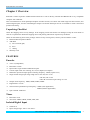
PXI2394 Data Acquisition
PXI2394
User’s Manual
Beijing ART Technology Development Co., Ltd.
BUY ONLINE at art-control.com/englishs or CALL+86-10-51289836(CN)
1
PXI2394 Data Acquisition
Contents
Contents ................................................................................................................................................................................2
Chapter 1 Overview ..............................................................................................................................................................4
Chapter 2 Components Layout Diagram and a Brief Description .......................................................................................6
2.1 The Main Component Layout Diagram ..................................................................................................................6
2.2 The Basic Block Diagram .......................................................................................................................................6
2.3 Signal Input/Output Connector ...............................................................................................................................7
2.4 Indicator Lights .......................................................................................................................................................7
2.5 Physical ID of DIP Switch ......................................................................................................................................7
Chapter 3 Signal Connectors................................................................................................................................................8
3.1 The Definition of Signal Input/Output Connector ..................................................................................................8
Chapter 4 Connection Ways for Input and Output..............................................................................................................10
4.1 Connection Method for Single-ended Input..........................................................................................................10
4.2 Connection Method for Differential Inputs...........................................................................................................10
4.3 Connection Method for Monopulse Signal Input..................................................................................................11
4.4 Connection Method for Monopulse Signal Input..................................................................................................11
4.4.1 Up/Down Signal Input ...............................................................................................................................11
4.4.2 Rising Edge Signal Input ...........................................................................................................................12
4.4.3 Falling Edge Signal Input...........................................................................................................................12
4.5 Connection Method for Digital Signal Input/Output ............................................................................................13
4.5.1 Digital Signal Input ....................................................................................................................................13
4.5.2 Digital Signal Output .................................................................................................................................13
Chapter 5 Method of Using a Variety of Functions ............................................................................................................14
5.1 Input Mode............................................................................................................................................................14
5.1.1 Disabled Mode ...........................................................................................................................................14
5.1.2 Quadrature Input Counter Mode ................................................................................................................14
5.1.3 Dipulse Mode.............................................................................................................................................14
5.1.4 Pulse/Direction Mode.................................................................................................................................14
5.2 Latch Mode ...........................................................................................................................................................14
5.2.1Software Latch ............................................................................................................................................14
5.2.2 Index Latch ................................................................................................................................................14
5.2.3 Timer Latch ................................................................................................................................................15
5.2.4 DI0~DI3 Latch ...........................................................................................................................................15
5.3 Interrupt.................................................................................................................................................................15
5.3.1Counter Interrupt.........................................................................................................................................15
5.3.2 Timer and DI Interrupt ...............................................................................................................................15
5.4 Other Parameter Setting ........................................................................................................................................15
5.4.1 Counter Overflow Lock .............................................................................................................................15
5.4.2 Counter Underflow Lock ...........................................................................................................................15
5.4.3 Digital Filter...............................................................................................................................................16
5.4.4 Reset Value.................................................................................................................................................16
5.4.5 Enable Index Reset.....................................................................................................................................16
5.5 DO Setting ............................................................................................................................................................16
BUY ONLINE at art-control.com/englishs or CALL+86-10-51289836(CN)
2
PXI2394 Data Acquisition
5.5.1 DO Control Mode ......................................................................................................................................16
5.5.2 DO Output Mode .......................................................................................................................................16
5.6 Timer Setting.........................................................................................................................................................16
5.7 Comparer Setting ..................................................................................................................................................16
Chapter 6 Notes and Warranty Policy ................................................................................................................................17
6.1 Notes .....................................................................................................................................................................17
6.2 Warranty Policy.....................................................................................................................................................18
Products Rapid Installation and Self-check ........................................................................................................................18
Rapid Installation ........................................................................................................................................................18
Self-check ...................................................................................................................................................................19
Delete Wrong Installation ...........................................................................................................................................19
BUY ONLINE at art-control.com/englishs or CALL+86-10-51289836(CN)
3
PXI2394 Data Acquisition
Chapter 1 Overview
PXI2394 is a data acquisition module based on PXI bus. It can be directly inserted into IBM-PC/AT or any compatible
computer with a PXI slot.
This card includes four 32-bit quadruple AB phase encoder counters, 8-bit timer with multi range time-base selector, four
isolated digital inputs, and four isolated digital outputs. Its flexible interrupts sources are suitable for motor control and
position monitoring.
Unpacking Checklist
Check the shipping carton for any damage. If the shipping carton and contents are damaged, notify the local dealer or
sales for a replacement. Retain the shipping carton and packing material for inspection by the dealer.
Check for the following items in the package. If there are any missing items, contact your local dealer or sales.
¾ PXI2394 Data Acquisition Board
¾ ART Disk
a) user’s manual (pdf)
b) drive
c) catalog
¾ Warranty Card
FEATURES
Encoder
¾
¾
¾
¾
¾
¾
¾
¾
¾
¾
Axes: 4 (independent)
Resolution: 32 bits
Input mode: single-ended or differential inputs
Counter input mode: not counting, X1, X2, X4, dipulse, monopulse
Maximum input and output signals switching frequency: 10kHz (square wave)
Single-ended voltage input range: High Level: CH-=0V, CH+>2.8V
CH-=0V, CH+<0.8V
CH-/CH+ maximum input voltage is ±12V
Sample clock frequency: 1MHz, 2MHz, 4MHz, 8MHz
Digital Filter: 4 levels
The maximum quadrature input frequency: 1MHz (with digital filter)
4MHz (without digital filter)
Opto-isolated: 2500Vrms
Timer
¾
¾
Resolution: 8-bit
Time base: 50KHz, 5KHz, 500Hz, 50Hz, 5Hz
Isolated Digital Input
¾
¾
Channels: 4
Input voltage range: 50VDC<VIH<30VDC
BUY ONLINE at art-control.com/englishs or CALL+86-10-51289836(CN)
4
PXI2394 Data Acquisition
¾
¾
¾
VIL<3.4VDC
Opto-isolation: 2500Vrms
Opto-isolation response time: <100ns
Over-voltage protection: 70V
Digital Output
¾
¾
¾
¾
Channel No.: 4
Opto-isolation: 2500Vrms
Opto-isolation response time: <100ns
Supply voltage: TTL
Others
¾
¾
Interrupt source: counter overflow, counter underflow, index input, timer, digital input
Counter lock source : software, timer, index, digital input
BUY ONLINE at art-control.com/englishs or CALL+86-10-51289836(CN)
5
PXI2394 Data Acquisition
Chapter 2 Components Layout Diagram and a Brief Description
2.1 The Main Component Layout Diagram
2.2 The Basic Block Diagram
Address, Controller, Date
Bus
SE/DI Isolation Input Circuit
32-bit Up/Down
Counter
Count Mode
Controller
Digital Filter
CH0-A
CH0-B
CH0-Z
32-bit Up/Down
Counter
Count Mode
Controller
Digital Filter
CH1-A
CH1-B
CH1-Z
32-bit Up/Down
Counter
Count Mode
Controller
Digital Filter
32-bit Up/Down
Counter
Count Mode
Controller
Digital Filter
CH2-A
CH2-B
CH2-Z
CH3-A
CH3-B
CH3-Z
DO/I-0
DO/I-1
DO/I-2
DO/I-3
Programmable Time-Base
Generator
Interrupt Controller
PXI Interface
PXI Bus
BUY ONLINE at art-control.com/englishs or CALL+86-10-51289836(CN)
6
PXI2394 Data Acquisition
2.3 Signal Input/Output Connector
CN1: signal input/output connector
DID: Physical ID Setting
2.4 Indicator Lights
LED5V: 5V power supply indicator light
LED3.3V: 3.3V power supply indicator light
2.5 Physical ID of DIP Switch
When the PC is installed more than one PXI2394 , you can use the DIP switch to set a physical ID number for each
board, which makes it very convenient for users to distinguish and visit each board in the progress of the hardware
configuration and software programming. The following eight-place numbers are expressed by the binary system: When
DIP switch points to "ON", that means "1", and when it points to the other side, that means "0." As they are shown in the
following diagrams: place "ID7" is the high place."ID0" is the low place, and the black part in the diagram represents the
location of the switch.
The above chart shows"1111", so it means that the physical ID is 15.
The above chart shows"0111", so it means that the physical ID is 741.
ID3
OFF(0)
ID2
OFF(0)
ID1
OFF(0)
ID0
ID(Hex)
ID(Dec)
OFF(0)
0
0
OFF(0)
OFF(0)
OFF(0)
ON(1)
1
1
OFF(0)
OFF(0)
ON(1)
OFF(0)
2
2
OFF(0)
OFF(0)
ON(1)
3
3
OFF(0)
OFF(0)
4
4
OFF(0)
ON(1)
ON(1)
ON(1)
OFF(0)
5
ON(1)
ON(1)
OFF(0)
5
OFF(0)
OFF(0)
ON(1)
6
6
OFF(0)
ON(1)
ON(1)
7
7
ON(1)
OFF(0)
OFF(0)
ON(1)
OFF(0)
8
8
ON(1)
OFF(0)
OFF(0)
9
9
ON(1)
OFF(0)
ON(1)
A
10
ON(1)
OFF(0)
ON(1)
B
11
ON(1)
ON(1)
OFF(0)
ON(1)
OFF(0)
C
12
ON(1)
ON(1)
OFF(0)
D
13
ON(1)
ON(1)
ON(1)
ON(1)
OFF(0)
E
14
ON(1)
ON(1)
ON(1)
ON(1)
F
15
ON(1)
OFF(0)
BUY ONLINE at art-control.com/englishs or CALL+86-10-51289836(CN)
7
PXI2394 Data Acquisition
Chapter 3 Signal Connectors
3.1 The Definition of Signal Input/Output Connector
CN1: 68-pin SCSI 37 core plug on the CN1 pin definition
AGND
68
34
IDO0
AGND
67
33
IDO1
AGND
66
32
IDO2
AGND
65
31
IDO3
AGND
64
30
AGND
AGND
63
29
IDI0
AGND
62
28
IDI1
AGND
61
27
IDI2
AGND
60
26
AGND
59
25
IDI3
EIDI_COM
AGND
58
24
CH3Z+
AGND
57
23
CH3Z-
AGND
56
22
CH3B+
AGND
55
21
CH3B-
AGND
54
20
CH3A+
AGND
53
19
CH3A-
AGND
52
18
CH2Z+
AGND
51
17
CH2Z-
AGND
50
16
CH2B+
AGND
49
15
CH2B-
AGND
48
14
CH2A+
AGND
47
13
CH2A-
AGND
46
AGND
12
11
CH1Z+
45
AGND
44
10
CH1B+
AGND
43
9
CH1B-
AGND
42
8
CH1A+
AGND
41
7
CH1A-
AGND
40
6
CH0Z+
AGND
39
5
CH0Z-
AGND
38
4
CH0B+
AGND
37
3
CH0B-
AGND
36
2
CH0A+
AGND
35
1
CH0A-
CH1Z-
Signal Name
Type
Definition
CH<0..3>A+
Input
Channel<0..3>A differential positive-input.
CH<0..3>A-
Input
Channel<0..3>A differential negative-input.
CH<0..3>B+
Input
Channel<0..3>B differential positive-input.
BUY ONLINE at art-control.com/englishs or CALL+86-10-51289836(CN)
8
PXI2394 Data Acquisition
CH<0..3>B-
Input
Channel<0..3>B differential negative-input.
CH<0..3>Z+
Input
Channel<0..3>Z differential positive-input.
CH<0..3>Z-
Input
Channel<0..3>Z differential negative-input.
IDI<0..3>
Input
Isolated Digital Input, Channels 0 through 3.
IDO<0..3>
EIDI_COM
Output
Isolated Digital Output, Channels 0 through 3.
GND
Digital Isolated Ground.
AGND
GND
External Ground.
BUY ONLINE at art-control.com/englishs or CALL+86-10-51289836(CN)
9
PXI2394 Data Acquisition
Chapter 4 Connection Ways for Input and Output
4.1 Connection Method for Single-ended Input
4.2 Connection Method for Differential Inputs
BUY ONLINE at art-control.com/englishs or CALL+86-10-51289836(CN)
10
PXI2394 Data Acquisition
4.3 Connection Method for Monopulse Signal Input
4.4 Connection Method for Monopulse Signal Input
4.4.1 Up/Down Signal Input
BUY ONLINE at art-control.com/englishs or CALL+86-10-51289836(CN)
11
PXI2394 Data Acquisition
4.4.2 Rising Edge Signal Input
4.4.3 Falling Edge Signal Input
BUY ONLINE at art-control.com/englishs or CALL+86-10-51289836(CN)
12
PXI2394 Data Acquisition
4.5 Connection Method for Digital Signal Input/Output
4.5.1 Digital Signal Input
4.5.2 Digital Signal Output
BUY ONLINE at art-control.com/englishs or CALL+86-10-51289836(CN)
13
PXI2394 Data Acquisition
Chapter 5 Method of Using a Variety of Functions
5.1 Input Mode
5.1.1 Disabled Mode
PXI2394 will not accept input.
5.1.2 Quadrature Input Counter Mode
Quadrature input consists of two square wave inputs(A and B), which are 90°out of phase. There are three different
counting methods in quadrature input mode:
X1: The counter will increment (or decrement) the counter whenever a rising edge occurs on input channel A.
X2: The counter will increment (or decrement) the counter whenever a rising or falling edge occurs on input channel A.
X4: The counter will increment (or decrement) the counter whenever a rising edge occurs on input channel A or B.
5.1.3 Dipulse Mode
In dipulse mode the PXI2394 uses two input pulses as counting sources: one for clockwise and one for counterclockwise
counting. The counter will increment whenever a rising edge occurs on channel A. it will decrement whenever a rising
edge occurs on channel B.
5.1.4 Pulse/Direction Mode
In pulse/direction mode the PXI2394 uses one input line (A) for pulse input and one line (B) for direction. If channel B is
high (1), the counter will decrement whenever a rising edge occurs in channels A. if channel B is low (0), the counter
will increment whenever a rising edge occurs on channel A.
5.2 Latch Mode
When you read a counter, you are actually reading a value latched into a buffer. The PXI2394 provide seven different
latching mode, only one of which is active at any given time. The PXI2394’s latching modes are as follows:
5.2.1Software Latch
Whenever you read a channel’s data registers, the counter values will be latched in the buffer.
5.2.2 Index Latch
A rising edge on the channel Z will latch the channel’s counter value.
BUY ONLINE at art-control.com/englishs or CALL+86-10-51289836(CN)
14
PXI2394 Data Acquisition
5.2.3 Timer Latch
The card latches the counter value on a rising edge of pulses from the card’s on-board timer.
5.2.4 DI0~DI3 Latch
A rising edge on the DI0, DI1, DI2 or DI3 will latch the counter value for the channel.
5.3 Interrupt
5.3.1Counter Interrupt
1. Overflow interrupt control: Interrupt when count value reaches the maximum count value and overflow to 0.
2. Underflow interrupt control: Interrupt when count value reaches 0 and overflow to the maximum count value.
3. Index interrupt control: Interrupt when channel Z signal has a rising edge.
4. Greater than comparative value: Interrupt when the count value is greater than the user-defined comparative value.
5. Less than comparative value: Interrupt when the count value is less than the user-defined comparative value.
5.3.2 Timer and DI Interrupt
Timer: The timer sends a interrupt signal after the user-defined time interval.
DI0~DI3: Interrupt when DI0~DI3 input signal is high level.
Message No.: Record the number of interruptions.
5.4 Other Parameter Setting
5.4.1 Counter Overflow Lock
Stop counting when the counter value reaches the maximum count value, or else overflow to 0.
5.4.2 Counter Underflow Lock
Stop counting when the counter value reaches 0, or else overflow to the maximum count value.
BUY ONLINE at art-control.com/englishs or CALL+86-10-51289836(CN)
15
PXI2394 Data Acquisition
5.4.3 Digital Filter
Apply to the use environment of the scene is a bad situation.
5.4.4 Reset Value
When this checkbox is selected, the counter’s reset initial is 0x8000000, or else the reset initial is 0.
5.4.5 Enable Index Reset
When this checkbox is selected, the counter reset if channel Z signal has a rising edge.
5.5 DO Setting
5.5.1 DO Control Mode
Common: Users set the output high level and low level
Specified: appoint the digital output mode is “Pulse Output” or “Level Output”
5.5.2 DO Output Mode
Pulse Output: Output high level when the count value is equal to the comparative value, or else output low level.
Level Output: Output high level all the time after the count value is equal to the comparative value.
5.6 Timer Setting
Set the timer’s time base, divider and time interval.
5.7 Comparer Setting
BUY ONLINE at art-control.com/englishs or CALL+86-10-51289836(CN)
16
PXI2394 Data Acquisition
Set the comparative value of each counter.
Chapter 6 Notes and Warranty Policy
6.1 Notes
In our products’ packing, user can find a user manual, a PXI2394 module and a quality guarantee card. Users must keep
quality guarantee card carefully, if the products have some problems and need repairing, please send products together
with quality guarantee card to ART, we will provide good after-sale service and solve the problem as quickly as we can.
When using PXI2394, in order to prevent the IC (chip) from electrostatic harm, please do not touch IC (chip) in the
front panel of PXI2394 module.
BUY ONLINE at art-control.com/englishs or CALL+86-10-51289836(CN)
17
PXI2394 Data Acquisition
6.2 Warranty Policy
Thank you for choosing ART. To understand your rights and enjoy all the after-sales services we offer, please read the
following carefully.
1. Before using ART’s products please read the user manual and follow the instructions exactly. When sending in
damaged products for repair, please attach an RMA application form which can be downloaded from:
www.art-control.com.
2. All ART products come with a limited two-year warranty:
¾ The warranty period starts on the day the product is shipped from ART’s factory
¾ For products containing storage devices (hard drives, flash cards, etc.), please back up your data before sending
them for repair. ART is not responsible for any loss of data.
¾ Please ensure the use of properly licensed software with our systems. ART does not condone the use of pirated
software and will not service systems using such software. ART will not be held legally responsible for products
shipped with unlicensed software installed by the user.
3. Our repair service is not covered by ART's guarantee in the following situations:
¾ Damage caused by not following instructions in the User's Manual.
¾ Damage caused by carelessness on the user's part during product transportation.
¾ Damage caused by unsuitable storage environments (i.e. high temperatures, high humidity, or volatile chemicals).
¾ Damage from improper repair by unauthorized ART technicians.
¾ Products with altered and/or damaged serial numbers are not entitled to our service.
4. Customers are responsible for shipping costs to transport damaged products to our company or sales office.
5. To ensure the speed and quality of product repair, please download an RMA application form from our company
website.
Products Rapid Installation and Self-check
Rapid Installation
Product-driven procedure is the operating system adaptive installation mode. After inserting the disc, you can select the
appropriate board type on the pop-up interface, click the button【driver installation】; or select CD-ROM drive in
Resource Explorer, locate the product catalog and enter into the APP folder, and implement Setup.exe file. After the
installation, pop-up CD-ROM, shut off your computer, insert the PCI card. If it is a USB product, it can be directly
inserted into the device. When the system prompts that it finds a new hardware, you do not specify a drive path, the
operating system can automatically look up it from the system directory, and then you can complete the installation.
BUY ONLINE at art-control.com/englishs or CALL+86-10-51289836(CN)
18
PXI2394 Data Acquisition
Self-check
At this moment, there should be installation information of the installed device in the Device Manager (when the device
does not work, you can check this item.). Open "Start -> Programs -> ART Demonstration Monitoring and Control
System -> Corresponding Board -> Advanced Testing Presentation System", the program is a standard testing procedure.
Based on the specification of Pin definition, connect the signal acquisition data and test whether AD is normal or not.
Connect the input pins to the corresponding output pins and use the testing procedure to test whether the switch is
normal or not.
Delete Wrong Installation
When you select the wrong drive, or viruses lead to driver error, you can carry out the following operations: In Resource
Explorer, open CD-ROM drive, run Others-> SUPPORT-> PCI.bat procedures, and delete the hardware information that
relevant to our boards, and then carry out the process of section I all over again, we can complete the new installation.
BUY ONLINE at art-control.com/englishs or CALL+86-10-51289836(CN)
19