1
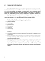
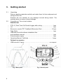
2 Contents 1. 2. 3. 4. 5. 6. 7. 8. 9. 10. 11. 12. Safety Precautions General Information Getting Started Calibration Operation Approved methods for microorganism cultivation Recommendations for creating personal settings for cultivation of microorganisms. Points that should be considered: 7.1 Temperature distribution specifics (psychrophiles, mesophiles, thermophiles) 7.2 Cell growth depending on rotation intensity 7.3 Aeration and types of recommended tubes 7.4. Cell growth depending on measurement frequency (aerobes, anaerobes) 7.4. Particle size and calibration coefficients 600nm/850nm 7.5. Linear range of OD measurement as a function of medium volume Specifications Maintenance Device calibration for maintenance Warranty and Claims Declaration of Conformity 3 1. Safety Precautions The following symbol means: Caution! Make sure you have fully read and understood the present Manual before using the equipment. Please pay special attention to sections marked by this symbol. GENERAL SAFETY Use only as specified in the operating manual provided. The unit should not be used if dropped or damaged. After transportation or storage keep the unit under room temperature for 2— hrs before connecting it to the electric circuit. Use only cleaning and decontamination methods recommended by the manufacturer. Do not make modifications in design of the unit. ELECTRICAL SAFETY 4 Do not plug the unit into the main socket without grounding, and do not use extension lead without grounding. Connect only to a power supply with voltage corresponding to that on the serial number label. Use only the external power supply unit provided with this product. Ensure that the external power supply unit and switch are easily accessible during use. Disconnect the unit from the electric circuit before moving. Turn off the unit by switching off the power switch and disconnecting the external power supply unit from the power socket. If liquid penetrates into the unit, disconnect it from the external power supply unit and have it checked by a repair and maintenance technician. Do not operate the unit in premises where condensation can form. Operating conditions of the unit are defined in the Specifications section. DURING OPERATION Do not operate the unit in environments with aggressive or explosive chemical mixtures. Please contact manufacturer for possible operation of the unit in specific atmospheres. Do not operate the unit if it is faulty or has been installed incorrectly. Do not use outside laboratory rooms. Do not check the temperature by touch. Use a thermometer. Always clean and decontaminate the rotor after operation. BIOLOGICAL SAFETY It is the user’s responsibility to carry out appropriate decontamination if hazardous material is spilt on or penetrates into the equipment. 5 2. General Information Real Time Cell Growth Logger is a device which can be used as an incubator with optical density measurement in real time. Temperature control allows using RTS-1C as an incubator, for example, to cultivate cells. Due to innovative mixing technology (reverse spinning of the sample around its own axis) it is possible to make OD measurement without probe interference. Developed software for recording, displaying and data analysis allows working in real time. Real Time Cell Growth Logger is equipped with a cooling unit that allows cooling the samples to +4°C and temperature profiling through sofware. The Real Time Cell Growth Logger is applicable in: Molecular biology Cell biology Biotechnology Biochemistry Chemistry Microbiology Features 6 Innovative mixing due to reverse spinning of the tube with the sample around its own axis; Due to innovative mixing technology it is possible to measure optical density and light scattering of the sample in real time without probe interference, maintaining process sterility; Changing the parameters such as temperature, revolution per minute and period of spinning in one direction, together with possibility of creating experiment algorithms (including temperature profiling, mixing intensity profiling, optical density control, etc.) allows both performance of difficult sequence of algorithms of fermentation process, and achieving consistent and repeatable results. Software possibilities: Remote tracking and control of fermentation process; Real-time registration of cell growth kinetics or particle suspension aggregation/ disaggregation processes; User graphs, including 3D graphs; Pause; Saving and loading result data; PDF and Excel spreadsheet reports Simultaneous connection of up to 10 units that allows, on one hand, to research the influence of different chemical and physical factors on fermentation process, and, on the other hand, to research the interdependance of those factors in matrix experiments. 7 3. Getting started 3.1. Unpacking Remove packing materials carefully and retain them for future shipment and storage of the unit. Examine the unit carefully for any damage incurred during transit. The warranty does not cover in-transit damage. Complete set. The unit set includes: Standard set 3.2. - RTS-1C, Real Time Cell Growth Logger with cooling ............................ 1 pce Lid .......................................................................................................... 1 pce Bioreactor vessels TPP TubeSpin® Bioreactor 50ml .......................... 20 pcs Data Cable............................................................................................. 1 pce USB disk drive with software installation files and installation manual .......................................................................... 1 pce External power supply ........................................................................... 1 pce Operating Manual, Certificate .............................................................. 1 copy Optional accessories USB hub with 10 ports ................................................................... on request Fig. 1 Rear panel 8 Fig. 2 Control panel 3.3. 3.4. - Set up: Place the unit on even, horizontal working surface; Connect the external power supply unit to the socket (fig. 1/1) on the rear side of the unit; Switch on the computer, if it was turned off; Install the software following the software installation procedure described in software installation manual. Bioreactor vessel features: Falcon type tubes. TPP TubeSpin® Bioreactor 50 type tubes are required to use the kid with openings; Working volume 10 - 30 ml; Conical form; 5 openings (A, B, C, D, E) of different size above the gas permeable, sterile PTFE filter of the screw cap; Openings can be sealed and by this, exchange adjusted to need; Steril gas exchange is guaranteed by the 0.22 µm filter membrane; Even with a high cell density the supply of oxygen through the openings is sufficient; Tube fits in a standard 50 ml centrifuge rotor. 9 4. Calibration The device is pre-calibrated at the factory for operation with 50ml falcon at temperature range from +4°C to +70°C and saves calibration data when being switched off. To verify the conformity of calibration follow the subsequent procedures: - 10 Take a 50 ml falcon tube; Add 10 ± 0.1ml distilled water; Close the cap of the falcon thoroughly; Insert the falcon into the socket (fig. 1/4); Set the volume parameter of the distilled water on the display (fig. 2/11); Press Run Stop key (fig. 2/9) (the device will start the OD measurement cycle by accelerating to 2000 rpm); The measurement cycle should complete after 15—20 seconds and OD value should appear on the display; If OD value equals 0 (±0.05 OD) then the device corresponds to factory precalibration settings and is suitable for use. 5. Operation Recommendations during operation Remove the falcon tube from the tube socket before connecting or disconnecting the external power supply during operation. It is recommended to start operation approximately 15 minutes after switching on the device (the time necessary for stabilization in the working mode). 5.1. Connect external power supply unit to electric circuit (fig. 1/1). 5.2. Turn on the unit by pressing the power switch on the rear panel (fig. 1/3). 5.3. Insert the tube into the socket (fig. 1/4). 5.4. Press the Select key (fig. 2/1) to choose a parameter that you want to change (the active parameter is blinking). 5.5. Use and keys (fig. 2/2) to set the necessary value (if the key is pressed for more than 2 seconds the parameter should change quicker). 5.6. It is possible to set time between optical density measurements (fig. 2/3), spinning speed (fig. 2/4), temperature (fig. 2/5), time between Reverse Spins (fig. 2/8), operating volume (fig. 2/11). Actual values of the temperature and speed are displayed on the display (fig. 2/6 and fig. 2/7). Note! After turning on the unit starts heating and continues to maintain the temperature regardless of other operations. 5.7. Press the Run Stop key (fig. 2/9) to start and stop operation. 5.8. Press the Run Stop key (fig. 2/9) to stop the operation. Caution! Operation stop will not stop the heating process. To stop heating process set temperature has to be decreased manually until “off” indication appears (fig. 2/5). 5.9. After finishing the operation switch OFF the unit with the Power switch (fig. 1/3). 5.10. Disconnect external power supply unit from electric circuit (fig. 1/1). 11 6. Approved methods for microorganism cultivation We are completely aware that the world of microorganisms is infinite, and each strain requires its own growth optimization. New methods for cultivation of microorganisms using RTS-1C technology will, with no doubt, increase and we will inform our customers about it. Here are the 3 approved methods that were developed by Biosan application lab: 6.1. Facultative anaerobe Escherichia Coli: 2000 rpm (vessel spinning speed), 1 s-1 (Reverse Spin Frequency, RSF), 37° C (socket temperature), 15 ml (sample volume in testing vessel), 10 min., but not less (Measurement Frequency, MF) 6.2. Thermophilic aerobe Thermophilus sp.: 2000 rpm, 1 s-1 RSF, 70° C (Real tube temperature 5°C lower), 15 ml 10 min MF Evaporation rate at 70° C = 5 ml / 24 h (please adjust Volume parameter accordingly for measurement system to work correctly) 6.3. Aerotolerant anaerobe L. acidophilus: 0 rpm, 0 s-1 RSF, 37° C, 30 ml, 10 min MF We recommend using Profiling/Cycling preset “”No mixing, OD meas.” for homogeneous distribution of cell suspension in the bioreactor tube prior to measurement 6.4. Currently studies are being conducted to better understand the advantages of reverse spin (RS) technology for growing different types of microorganisms such as yeast and lactic acid bacteria. 6.5. It is possible for the end-user to contact the manufacturer for advising or suggesting a required microorganism or strain for cultivation to be tested. Please contact the R&D department of Biosan at these e-mail adress: [email protected], [email protected], Igor Bankovsky, consulting biotechnologist on application questions. 12 7. Recommendations for creating personal settings for cultivation of microorganisms. Points that should be considered: 7.1 Temperature distribution specifics (psychrophiles, mesophiles, thermophiles) The optimal growth temperatures of microorganisms are divided three principal groups (see Fig. 3): Fig. 3 Temperature boarders and optimal growth zones of prokaryotes and their classification. I. Psychrophiles 1; 2 —facultative. II. Mesophiles. III. thermophiles: 3 —thermotolerant 4 —facultative; 5 —obligate; 6 —extremophile Thick line mark represents optimal growth temperature. 7.1.1 For psychrophiles the device must be installed in a cold room or refrigerated chamber. Despite the active cooling device, the sample is heated through the open upper part of falcon tube. Moreover, it also should be considered that the actual temperature of the reactor will always differ from the actual temperature of the sample because of its rotation (at low temperatures below 10 ° C) and will be higher. 13 7.1.2 For mesophilic microorganisms the device can be situated at room temperature. 7.1.3 For thermophilic microorganisms please observe Fig. 4, where comparison of thermoblock temperature, real temperature in the tube depending on rotation intensity can be observed. Fig. 4. Comparison of thermoblock temperature, real temperature in the tube depending on rotation intensity. The end point data was collected 1:30h after start of the heating process from room temperature 14 7.2 Cell growth depending on rotation intensity It is known that aeration affects the growth and growth rate of aerobic microorganisms. The reverse spin frequency affects the rate of oxygen uptake in the bioreactor. Results obtained indicate that the maximum rate of cell division is detected at a frequency of 1 Reverse Spin per second (1 s -1) at a speed of 2000 rpm. The increase of pause between reverse spins reduces cell growth rate, reaching 50% of the maximum value, when RS frequency is 30 s-1 (see Fig 5. and Fig. 6.). Fig 5. Influence of Frequency of Reverse Spinning on the Growth kinetics (ΔOD(λ=850nm)/Δt) vs Time of fermentation (hrs). 7.2.1. Legend of experiment (Fig. 5.): Real Time Cell Growth Logger RTS-1C was used with 850 nm LED, volume of LB media in 50 ml Falcon tube is approximately 15 ml, Reverse Spin Frequency 1, 2, 4, 8, 16, 30 s -1, measurement frequency (MF) is approximately 10 min-1, reactor rotation speed 2000 rpm , temperature 37° C, diameter of filter pores (for aeration) 0.25 μm. 15 Fig 6. Influence of Frequency of Reverse Spinning on the Growth kinetics (ΔOD(λ=850nm)/Δt) vs Time of fermentation (hrs). 7.3. 16 Aeration and types of recommended tubes. For aerobic microorganisms, we recommend using tubes that are supplied by us (TPP TubeSpin® Bioreactor 50ml), but for aerotolerant anaerobes like Lactobacillus acidophilus it is necessary to use test tubes with sealed lids (non-membrane). For obtaining optimal results growing aerotolerant anaerobes it is required to seal the screw cap of TPP TubeSpin® Bioreactor 50ml by tape. User can also use standard centrifuge tubes of 50 ml Falcon type, taking into account that the tube will be as transparent as TPP TubeSpin® Bioreactor tube. 7.4. 7.5. Particle size and calibration coefficients 600nm/850nm Calibration of the instrument is designed for specific microorganism size of 0.4-0.8 x 1-3 μm and a cell volume of about 0.6-0.7 μm3. In case of exceeding the allowable size, the measurement system will not work correctly. Optical density OD (λ = 850 nm) to OD (λ = 600 nm) conversion rate coefficient is equal to 2.2. Example of calculation: to convert 3.5 OD (λ = 850 nm) to OD (λ = 600 nm), simply multiply the result by 2.2, resulting in 7.7 OD (λ = 600 nm). Linear range of OD measurement as a function of medium volume (Fig. 7) Fig 7. Influence of Broth medium volume on linear range of OD measurement (ΔOD(λ=850nm)/Δt) vs Time of fermentation (hrs). As can be seen from Fig. 7, the device registers optical density of the sample in linear range until 15 OD (λ = 600 nm) at a volume of 10 ml, 8 OD (λ = 600 nm) at 20 ml and 6 OD (λ = 600 nm) at 30 ml. 17 8. Specification The unit is designed for operation at ambient temperature from +4°C to +40°C in a non-condensing atmosphere and maximum relative humidity 80% for temperatures up to 31°C decreasing linearly to 50% relative humidity at 40°C. 8.1. Measurement specifications Light source ........................................................................................ IR LED Wavelength (λ), nm ......................................................................... 850 ± 15 Measurement range, OD at 10-20 ml volume .................................................................... 0 - 10.00* at 20-30 ml volume .................................................................... 0 – 8.00** 8.2. 8.3. Measurement precision, OD ................................................................... ± 0.3 Real time measurement, min/measurement .......................................... 1 - 60 Time setting resolution, min .......................................................................... 1 Temperature specifications Setting range, °C ............................................................................... +4...+70 Bottom control range point, °C............................................ 15 below ambient Top control range point, °C ....................................................................... +70 Setting resolution, °C ................................................................................. 0.1 Stability, °C .............................................................................................. ±0.1 General specifications Recommended max. number of units connected to the software ............... 12 Sample volume, ml .............................................................................. 10 - 30 Speed range, rpm ............................................................................ 50 - 2000 Speed setting resolution, rpm ....................................................................... 1 Display ..................................................................................................... LCD Overall dimensions (W × D × H), mm ....................................... 130×212×200 Weight***, kg ............................................................................................. 1.5 Input current / power consumption .............................. 12 V DC, 3.3 A / 40 W External power supply ....................................... Input AC 100-240V 50/60Hz Output DC 12V Optional accessories USB 2.0 Hub Description 10 ports Catalogue number BS-010158-BK Biosan is committed to a continuous programme of improvement and reserves the right to alter design and specifications of the equipment without additional notice. * ** *** 18 0–25 OD λ600 nm equivalent 0–20 OD λ600 nm equivalent Accurate within ±10%. 9. Maintenance 9.1. If the unit requires maintenance, disconnect the unit from the mains and contact Biosan or your local Biosan representative. All maintenance and repair operations must be performed only by qualified and specially trained personnel. Standard ethanol (75%) or other cleaning agents recommended for cleaning of laboratory equipment can be used for cleaning and decontamination of the unit. Clean the rotor of the device from liquid droplets and possible contamination after finishing fermentation. 9.2. 9.3. 9.4. 19 10. Device calibration for maintenance Note! 10.1. 10.2. 10.3. 10.4. 10.5. 10.6. 10.7. 10.8. 10.9. 20 Only use this calibration if the measurement system does not work correctly. Turn on the device. Insert a 50 ml centrifuge tube filled with 10ml of H2O into the device. Set the Volume parameter to 10ml. Using control panel or software unit control panel, set RPM to 2000. Press Run/Stop button. Press and hold Select button until ”CC” command will appear and blink on the display. Press button and ”0.00” number will appear and blink on the display. Wait 15 seconds and press button. Device is now calibrated and will make one verification measurement 11. Warranty and Claims 11.1. The Manufacturer guarantees the compliance of the unit with the requirements of Specifications, provided the Customer follows the operation, storage and transportation instructions. 11.2. The warranted service life of the unit from the date of its delivery to the Customer is 24 months. Contact your local distributor to check availability of extended warranty. 11.3. If any manufacturing defects are discovered by the Customer, an unsatisfactory equipment claim shall be compiled, certified and sent to the local distributor address. Please visit www.biosan.lv, Technical support section to obtain the claim form. 11.4. The following information will be required in the event that warranty or postwarranty service comes necessary. Complete the table below and retain for your records. Model Real Time Cell Growth Logger with cooling RTS-1C Serial number Date of sale 21 12. Declaration of Conformity 22 23 Biosan SIA Ratsupites 7, build.2, Riga, LV-1067, Latvia Phone: +371 67860693, +371 67426137 Fax: +371 67428101 http://www.biosan.lv Version 1.01 - January 2015 24