1
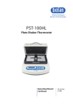
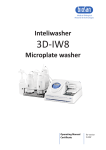
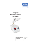
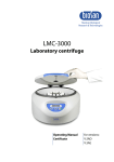
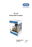
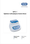
2 Contents 1. 2. 3. 4. 5. 6. 7. 8. 9. Safety Precautions ....................................................................................... 4 General Information ...................................................................................... 6 Getting started .............................................................................................. 6 Operation ...................................................................................................... 8 Specifications ............................................................................................. 12 How to choose a proper adapter ................................................................ 13 Maintenance ............................................................................................... 13 Warranty and claims ................................................................................... 14 Declaration of conformity ............................................................................ 15 3 1. Safety Precautions The following symbols mean: Caution! Make sure you have fully read and understood the present Manual before using the equipment. Please pay special attention to sections marked by this symbol. GENERAL SAFETY This unit is a state-of-the-art piece of equipment, which is extremely safe to operate. Nevertheless, it may lead to danger for users or others nearby if used by untrained staff, in an inappropriate way or for purposes other than those it was designed for. Save the unit from shocks or falling. Store and transport the unit in a horizontal position (see package label). After transportation or storage, keep the unit under room temperature for 23hrs before connecting to electric circuit. Before using any cleaning or decontamination methods except those recommended by the manufacturer, check with the manufacturer that the proposed method will not damage the equipment. Do not make modifications to the design of the unit. ELECTRICAL SAFETY Connect only to the external power supply with voltage corresponding to that on the serial number label. Use only the external power supply provided with this product. Ensure that the external power supply is easily accessible during use. Do not plug the unit into an ungrounded mains outlet, and do not use an ungrounded extension lead. Disconnect the unit from the electric circuit before moving. Disconnect the external power supply from mains outlet to turn off the unit. If liquid penetrates into the unit, disconnect it from the external power supply and have it checked by a repair and maintenance technician. Do not operate the unit in premises where condensation can form. Operating conditions of the unit are defined in the Specifications section. 4 DURING OPERATION Do not use rotors with visible signs of corrosion, wear or mechanical damage. Do not use the unit without the rotor safety cover. Do not operate the unit in environments with aggressive or explosive chemical mixtures. Please contact manufacturer for possible operation of the unit in specific atmospheres. Observe the safety area of 300 mm around the unit. Persons and hazardous materials must not be located in the safety area whilst the unit is operating. Do not centrifuge flammable or chemically active substances. Do not use outside laboratory rooms. Do not operate the unit if it is faulty or was installed incorrectly. Always fix rotor securely. Stop the operation immediately with the Stop key if any unusual noise occurs during acceleration, which can be due to improper rotor fixation. Use only original accessories (rotors, adapters, etc.) provided by the manufacturer and ordered specifically for this model BIOLOGICAL SAFETY According to EN 61010-2-020 a centrifuge without biological safety system is not considered a biologically safe and therefore cannot be used for centrifuging hazardous materials contaminated with toxic, radioactive or pathogenic microorganisms. Take additional measures if a contact of bare skin with hazardous substances is possible. Take care not to cut, puncture, or tear the gloves. Not one glove material is impervious to all substances. Disposable surgical or PVC gloves provide substantial but not complete protection. PVC gloves are probably more protective than surgical gloves, but they are stiffer and less tactile. Discard gloves after each use. It is the user's responsibility to carry out appropriate decontamination if hazardous material spills on or penetrates into the equipment. Some inner components are susceptible to contamination. Only qualified specialists, who are experienced in deactivations procedures, must perform cleaning these components for their future use. The user is responsible for decontaminate the unit before its decommissioning and utilization. 5 2. General Information After many years of Combined Centrifuge/Vortex concept success, we are proud to introduce the long awaited Centrifuge/Vortex for PCR plates, CVP-2, to the sample preparation market. The application range of CVP-2 is PCR plates: with skirts, semi-skirts or without them. The Spin-mix-spin technology is intended to spin-down micro volumes of reagents on the well’s bottom (first centrifugation spin), following mixing (mix) and spin-down the reagents again (second spin). We named this repetitive algorithm sms, spin-mix-spin. It aims at reducing the mistakes during sample preparation for PCR analysis. The algorithm was published for the first time and patented by Biol. Dr. V. Bankovskis (V. Bankovskis et al., Riga, Latvia, Pat. No. P94-74). CVP-2 is a fully automatic device for reproducing sms for 2 PCR plates at the same time, thus saving time considerably. A must-have instrument for PCR and DNA analyses laboratory. CVP-2 is 4 devices combined in 1: 1. Centrifuge –Maximum RCF: 245 × g (1500 rpm) 2. Vortex (regulation timer 0 – 60 s) 3. Centrifuge/Vortex 4. SMS for realization of the sms algorithm 3. Getting started 3.1. Unpacking. Remove packing materials carefully and retain them for future shipment or storage of the unit. Examine the unit carefully for any damage incurred during transit. The warranty does not cover in-transit damage. Warranty covers only the units transported in the original package. 3.2. Standart set. Package contents: Standard set CVP-2 Centrifuge/Vortex ....................................................................... 1 pce R-2MP rotor for PCR plates with fixation nut for fastening and safety cover .................................................................................... 1 pce AP-96 adapter for semi-skirted and non-skirted PCR plates, 96 wells .......................... 2 pcs wrench for rotor removing .................................................................. 1 pce key for cover unblocking (fixed into rear panel of the unit) .................... 1 pce external power supply ............................................................................ 1 pce power cable ........................................................................................... 1 pce Operating manual, Certificate .............................................................. 1 copy 6 - Optional accessories AP-384 adapter 384-well PCR plates (Eppendorf) .................... on request 3.3. 3.4. - - Setup. place the unit on the even, stable, horizontal and clean surface; remove protective film from the display; plug the power cord into the external power supply; plug the external supply into the power socket on the rear of the unit and position the unit so that there is easy access to the power switch and mains outlet; according to EN 61010-2-20 people and hazardous materials must not be within a 300 mm area around the device during the centrifuge operation; Rotor installation. connect the power cord to a properly grounded mains outlet. Switch on the power switch (I position) on the rear; press the Open key and open the lid by lifting it upwards by hand; unscrew the fixation nut (Fig. 1/1) counter clockwise using the wrench included in standard set and remove the nut. place the rotor and secure it tightly with the fixation nut, placing the nut with the key holes up (Fig.1/1) and turning it clockwise by the included wrench. place the safety cover (Fig. 1/2) on the rotor by pressing the cover clip (Fig. 1/3) down; close the centrifuge lid. Note! To close the lid, press down the middle part of the edge of the lid until the clicking sound is heard. Otherwise, the lid will not be secured properly, which will cause operation malfunction. turn off the centrifuge with switch on the rear (position O). Fig. 1. Rotor replacement 7 4. Operation Recommendations during operation Do not use rotors with visible signs of corrosion, wear or mechanical damage. Check the rotor, buckets for any signs of wear or corrosion, and replace if necessary. When using semi-skirted or non-skirted PCR plates, put the plate into an appropriate adapter. Insert the plate into the rotor with the adapter. Refer to section 6. How to choose a proper adapter. Load both PCR plates to balance the unit during operation. Before operation check PCR plates and ensure that they are closed properly. Content can be spilled from open PCR plates, endangering personnel working with hazardous materials. For proper mixing, it is recommended to fill PCR plates not more than 75% of their nominal volume. Seal the microplates with an appropriate adhesive film to avoid spilling the sample. Fig. 2. Front panel 4.1. 4.2. 4.3. 4.4. 8 Connect the external power supply to a properly grounded power socket. Turn on the power switch (I position) on the rear side of the unit. Lid unlocks automatically. Press the Open key (fig. 2/1) and open the lid by lifting it upwards by hand (indication “OPEN” will appear in the Mode bottom line, fig. 2/2). Lid will open only with rotor stopped. Remove the safety cover by lifting the safety cover clip. Insert TWO microtest plates in rotor one opposite another. 4.5. 4.6. 4.7. 4.7.1. 4.7.2. 4.7.3. 4.7.4. 4.8. 4.8.1. 4.8.2. 4.8.3. 4.8.3. 4.8.4. 4.8.5. Place the safety cover on the rotor and secure it by pressing the safety cover clip down tightly. Close the outer lid carefully and smoothly until the clicking sound is heard (indication “STOP” will appear in the Mode bottom line). Note! To close the lid, press down the middle part of the edge of the lid until the clicking sound is heard. Otherwise, the lid will not be secured properly, which will cause operation malfunction. Quick centrifugation. Press the QS (fig. 2/10) button for quick mixing / sedimentation and hold it pressed for the desired time. The unit will automatically when the QS button is released. Setting parameters. By pressing Select key (fig. 2/3) choose a parameter to change. Each pressing of the Select key consecutively activates parameters in operation cycle, currently active parameter is indicated by blinking. Use ▼ and ▲ keys (fig. 2/4) for setting the corresponding values (pressing a key for longer than 2 seconds will increase change rate). Speed (RPM) and spinning / mixing time (Time) can be changed during operation — when a new operation cycle starts, microprocessor automatically accept changes as current operation mode. Cycle count (Cycle) and operating mode (Mode) cannot be changed during operation. Mode (fig. 3/1) parameter can be one of the following: S.M.S. sms-algorithm mode. M.S. alternating centrifugation and vortexing. SPIN centrifugation only. MIX vortexing only. Sms-algorithm Select the sms-algorithm (indication S.M.S. of Mode parameter, fig. 3/1). Set the required centrifugation speed, from 300 to 1500 rpm (increment 100 rpm, fig. 3/2). Set the required centrifugation time, from 1 s to 30 min (increment 1 s, after 1 min - 1 min, fig. 3/3). Set the required vortexing speed, from 300 to 1200 rpm (increment 100 rpm, fig. 3/4). Set the required vortexing time, from 1 to 60 s (increment 1 s, fig. 3/5). Set the required sms-algorithm cycle count, from 1 to 999 (fig. 3/6). Fig. 3. Sms-algorithm 9 4.9. Centrifugation + vortexing 4.9.1. Select the alternating centrifugation and vortexing algorithm (indication M.S. of Mode parameter, fig. 4/1). 4.9.2. Set the required centrifugation speed, from 300 to 1500 rpm (increment 100 rpm, fig. 4/2) 4.9.3. Set the required centrifugation time, from 1 s to 30 min (increment 1 s, after 1 min - 1 min, fig. 4/3). 4.9.3. Set the required vortexing speed, from 300 to 1200 rpm (increment 100 rpm, fig. 4/4). 4.9.4. Set the required vortexing time, from 1 to 60 s (increment 1 s, fig. 4/5). 4.9.5. Set the required sms-algorithm cycle count, from 1 to 999 (fig. 3/6). Fig. 4. Centrifugation + vortexing 4.10. Centrifugation 4.10.1. Select the centrifugation mode (indication SPIN of Mode parameter, fig. 5/1). 4.10.2. Set the required centrifugation speed, from 300 to 1500 rpm (increment 100 rpm, fig. 5/2) 4.10.3. Set the required centrifugation time, from 1 s to 30 min (increment 1 s, after 1 min - 1 min, fig. 5/3). Fig. 5. Centrifugation 10 4.11. Vortexing 4.11.1. Select the vortexing mode (indication MIX of Mode parameter, fig. 6/1). 4.11.2. Set the required vortexing speed, from 300 to 1200 rpm (increment 100 rpm, fig. 6/2). 4.11.3. Set the required vortexing time, from 1 to 60 s (increment 1 s, fig. 6/3). Fig. 6. Vortexing 4.12. Press Run key (fig. 2/5) to start operation. 4.13. Rotor will begin rotating and on the display, indication RUN (fig. 2/2), cycle countdown (fig. 2/6) and changing parameters of the current mode (fig. 2/7 and fig. 2/8). 4.14. Operation can be stopped before the set number of cycles elapses if necessary by pressing the Stop key (fig. 2/9). 4.15. Unit stops automatically after executing set number of cycles (blinking indication STOP (fig. 2/2) on the display) and the lid unlocks automatically. A sound signal is emitted after full stop of the rotor. Press Stop key (fig. 2/9) to stop the signal. 4.16. At the end of operation set the power switch in position O (OFF) on the rear. Disconnect the external power supply from electric circuit. Note: The electrical lid lock allows opening the lid only when the unit is connected to the mains and is turned on. 4.17. Lid emergency opening Disconnect the power cord from external power supply unit. Wait until the rotor stops completely. Insert the provided lid unblocking key (found on the rear panel of the unit) into opening on the right side of the unit and press to unlock the lid. 11 5. Specifications The unit is designed for operation in cold rooms, incubators and closed laboratory rooms at ambient temperature from +4°C to +40°C in a non-condensing atmosphere and maximum relative humidity 80% for temperatures up to 31°C decreasing linearly to 50% relative humidity at 40°C. Speed setting range Centrifugation ....................................................................... 300 — 1500 rpm Vortexing .............................................................................. 300 — 1200 rpm Speed setting increment ................................................................... 100 rpm Relative centrifugal force ........................................................... up to 245 x g Centrifugation mode time range .................................................. 1 s - 30 min Centrifugation mode time increment ........................... 1 s; after 1 min - 1 min Vortex mode time range ..................................................................... 0 - 60 s Vortex mode time increment ...................................................................... 1 s Number of programmable cycles .............................................. 1 - 999 cycles Maximum plate height ......................................................................... 17 mm Display .................................................................................. LCD, 64х128 px Safety measures.......................................................................Lid with a lock Dimensions .........................................................................285x350x190 mm Weight* ............................................................................................... 6,15 kg Operating voltage/power consumption .......................... 24 V, 750 mA / 18 W External power supply input.............. in AC 100-240V 50/60 Hz, out DC 24 V Optional accessories R-2MP AP-96 AP-384 Description Rotor for PCR plates, with a fixator lid Set of 2 adapters for semiskirted and unskirted 96-well PCR plates Set of 2 adapters for 384-well PCR plates (Eppendorf) Catalogue number BS-010219-AK BS-010219-DK BS-010219-EK Biosan is committed to a continuous program of improvement and reserves the right to alter design and specifications of the equipment without additional notice. * 12 Accurate within ± 10%. 6. How to choose a proper adapter 6.1. Displayed in the table below are PCR plate types in relation to available adapters. Effective mixing Do not use Plate type 96-well skirted PCR plate Piko PCR plates, in frame, 4 pcs/frame 96-well semi-skirted PCR plate 96-well non-skirted PCR plate 384-well PCR plate (Eppendorf) Warning! No adapter AP-96 adapter AP-384 adapter PCR plate height inside an adapter should not be higher than 17 mm. 7. Maintenance 7.1. If the unit requires maintenance, disconnect the unit from electric circuit and contact Biosan or your local Biosan representative. Only qualified and specially trained personnel must perform all maintenance and repair operations. Standard ethanol (75%) or other cleaning agents recommended for cleaning of laboratory equipment can be used for cleaning and disinfection of the unit. Follow these steps for cleaning the rotor: to open a powered unit, press Open key (fig. 3/1) and open the outer lid lifting it upwards by hand; to open an unpowered unit, insert the provided lid unblocking key (screwed in the rear panel of the unit) into opening on the right side of the unit and press; open the rotor safety cover by lifting the cover clip by hand (fig.1/3); holding the rotor with one hand, unscrew rotor fixation nut, turning it counterclockwise using included wrench; retrieve the rotor and perform necessary cleaning. The rotor is autoclavable (120°С, 20 min); after cleaning, place the rotor and secure it tightly with the fixation nut, placing the nut with the key holes up and turning it clockwise by securing wrench; place the rotor safety cover on the rotor pressing the cover clip down tightly. 7.2. 7.3. - 13 8. Warranty and claims 8.1. The Manufacturer guarantees the compliance of unit with the requirements of Specifications, provided the Customer follows the operation, storage and transportation instructions. The warranted service life of unit from date of delivery to the Customer is 24 months. Contact your local distributor to check availability of extended warranty. Warranty covers only the units transported in the original package. If any manufacturing defects are discovered by the Customer, an unsatisfactory equipment claim shall be compiled, certified and sent to the local distributor address. Please visit www.biosan.lv, Technical support section to obtain the claim form. The following information will be required in the event that warranty or postwarranty service comes necessary. Complete the table below and retain for your records. 8.2. 8.3. 8.4. 8.5. Model Serial number Date of sale 14 Centrifuge/Vortex for PCR plates CVP-2 9. Declaration of conformity 15 Biosan SIA Ratsupites 7, build.2, Riga, LV-1067, Latvia Phone: +371 67426137 Fax: +371 67428101 http://www.biosan.lv Edition 1.01 — May 2015