1
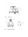
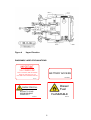
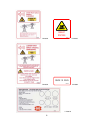
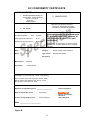
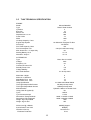
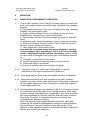
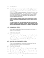
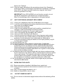
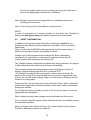
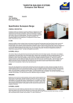
TABLE OF CONTENTS
Section
Subject
Page
1
WARRANTY
3
2
2.1
2.2
2.3
WARNING & SAFETY INSTRUCTIONS
Warning
Safety instructions
Instruction & Safety Labels on Machine
3
3
3
4
3
3.1
3.2
3.3
3.4
3.5
GENERAL
Using the operation & maintenance manual
Telelight description
Marking
EC Declaration of Conformity
Technical information
6
6
6
7
7
9
4
4.1
4.2
4.3
4.4
4.5
4.6
4.7
4.8
4.9
4.10
4.11
OPERATION
Inspection & preliminary operation
Manoeuvring
Maximum wind speeds
Earth requirements
Miniature circuit breakers
Starting the engine
Unit positioning and mast deployment
Operating the lights
Outlet power sockets
Lowering of mast
Preparing for removal from site
10
10
11
11
11
11
11
12
13
13
13
13
5.
5.1
5.2
5.3
5.4
TRANSPORT and STORAGE
Prior to transporting
Lifting the Telelight
Transporting by lorry
Storage
14
14
14
15
15
6
6.1
6.2
6.3
6.4
MAINTENANCE
Service
Safety information
Maintenance
Diesel generator maintenance
15
15
17
17
18
2
1.
WARRANTY
Warranty pertaining to your Telelight is explained in the Company’s separate
booklet entitled Registration & Warranty Information (RW1).
This booklet should be read in conjunction with these operator’s guidance
notes.
2.
WARNING & SAFETY INSTRUCTION
Failure to follow the warning instructions could result in severe injury or death to
the operator, a bystander or a person inspecting or repairing the machine.
2.1
WARNING
Operators should be trained in the safe use of the Telelight. If training has not
been carried out this should be reported to to your designated Company safety
officer. Do not operate the Telelight unless trained in its safe use.
Voltage used in this equipment can endanger life. Before attempting
replacement of components or maintenance operations, ensure that any power
supply and the generator are switched off.
The engine and generator set comprises components and fluids that, in
operation, are subject to high temperature. Caution is required to avoid burns
and scalding.
The Telelight is equipped with moving parts, pulleys & belts. Be careful in the
vicinity of the machine and avoid wearing loose clothing.
In case of fire do not use water. Use only an appropriate fire extinguisher.
Do not operate the Telelight in poorly ventilated areas, as exhaust gasses can
be extremely dangerous/fatal.
2.2
SAFETY INSTRUCTIONS
For safety operation observe the following instructions:
Exhaust gases
The exhaust gases contain harmful carbon monoxide. Operate the Telelight in
a spacious, well ventilated, area.
Electric shock prevention
Never touch the Telelight with wet hands.
IMPORTANT: Ensure the Telelight is EARTHED correctly.
3
Fire prevention
Avoid placing any flammable materials near the exhaust outlet during
operation.
When filling the fuel tank be sure to stop the engine and take care not to
spill fuel. Do not refuel near fire, flame or sparks. Do not smoke whilst
refuelling. Wipe off any spilt fuel immediately before re-use.
Other precautions
Never allow untrained persons to operate the Telelight.
Never move the Telelight during operation.
Operate the Telelight on a level base.
During use, keep the Telelight at distance from buildings and be sure that the
exhaust gases are not conveyed into buildings or closed environments.
Do not use the unit for lifting purposes for anything other than that for which it
is designed.
2.3 INSTRUCTION & SAFTEY LABELS ON MACHINE
The drawings are provided by way of example. The operating instruction,
warning & safety labels form an integral part of the Telelight. The unit you have
in your possession may differ in minor areas, the safety of the unit and the
information provided are nevertheless guaranteed.
DIAGRAMS/ LABEL EXPLANATIONS
Figure 1
Front Elevation
4
Figure 2
Side Elevation
Figure 3
Rear Elevation + Radiator
5
Figure 4
Upper Elevation
DIAGRAMS/ LABEL EXPLANATIONS
IMPORTANT
FULLY BUNDED UNIT
INSPECT REGULARLY, DRAIN AS REQUIRED
ENSURE ALL PLUGS ARE RE-FITTED.
KEEP DOORS CLOSED WHENEVER PRACTICAL.
BATTERY ACCESS
LA15459
LA03022
Diesel
Fuel
RADIATOR FILL
ALLOW TO COOL
DEPRESSURISE
CAREFULLY
LA01945C
FLAMMABLE
LA15447
6
WARNING
Do not operate lamps with glass
removed or broken.
Fully slacken BOTH clamps prior
to adjusting the lamp angle
LA15602
LA15462
Lamp Deployment
Transport Mode
L
Deployed Mode 1
WA
85
dB
Deployed Mode 2
LA15587
LA15649
LA15461
LOCK
MAST
ROTATOR
7
RELEASE
LA15647
FORKLIFT
POSITIONS
LA15584
LA15653
LA15653
ENGINE OIL DRAIN
LA15604
LA15654
LA15518
8
LA15654
3.
GENERAL
3.1
USING THE OPERATION & MAINTENANCE MANUAL
The scope of this document is to support the operator in safely deploying and
maintaining the Telelight.
This manual is organised in sections with the following information:
Section 1
Warranty Information.
Section 2
Section 2 contains the most important warning and safety instructions. More
specific safety information is contained in the specific sections for maintenance
and operation.
Section 3
Section 3 gives general information about the Telelight. This section also
includes help in handbook interpretation includes the technical data of the
Telelight and it’s main sub-assembly components. The information included in
this section may be duplicated or integrated in the diesel engine manuals, the
AC alternator manual and the control panel wiring diagrams.
Section 4
Section 4 refers to inspection and preliminary operation. It includes useful
information on deployment, outlet sockets, earthing, manoeuvring and
preparing for removal of Telelight from site.
Section 5
Section 5 provides information on transport, storage, lifting and handling the
Telelight.
Section 6
Section 6 provides information and procedures for routine, corrective
maintenance and advice on safety. The section also includes a timetable for
periodic maintenance. This section has to be read in conjunction with the
engine and alternator maintenance books that are supplied with the Telelight.
3.2
TELELIGHT DESCRIPTION
The Telelight consists of a diesel engine coupled to an AC alternator
mounted within a fully sound suppressed canopy. The rotating mast has 9
sections which extend by hydraulic cylinder and via wire ropes to a height of
9.0 metres. The mast is fitted with four Metal Halide Lamps.
9
An optional Power Tilt mechanism for remote adjustment of lamps is available.
Two external power sockets are provided. Four stabiliser legs are fitted for safe
operation when mast is deployed.
The entire unit is fully mounted onto a fast tow trailer with overrun and park
brake facility. Road lighting is fitted as standard.
The Serial Number of the Telelight should be quoted in any communication.
3.3
MARKING
The Telelight identification plate contains all the identification data required to
conform to the provisions for CE Marking. The plate is fitted on the front right
hand side of each Telelight, an example is shown in Fig. A.
SANDHURST MANUFACTURING CO.
SGN
KG
1-
MACHINE TYPE
SERIAL No.
ENGINE POWER
YEAR OF MANUFACTURE
KG
Sandhurst Mfg Co
Gosberton, Spalding,
Lincolnshire. PE11 4HG
Tel: 44 (0) 1775 840020
Fax: 44 (0) 1775 843063
100 KG
Figure A
3.4
7.7 kW @ 1500rpm
LA10454
SERIAL NO. PLATE
DECLARATION OF CONFORMITY
The Telelights supplied by Sandhurst Manufacturing Company Ltd are in
conformity with all the applicable EEC Directives and are furnished with an EC
Declaration of Conformity, an example is shown in Fig. B.
10
EC CONFORMITY CERTIFICATE
2. EC CONFORMITY CERTIFICATE No.
1. MANUFACTURER
1
Sandhurst Manufacturing Co
2 SMC/EC/2222
Roman Bank, Cherry Holt Road
Bourne, Lincolnshire
PE10 9LQ
United Kingdom
3. CERTIFICATE HOLDER
4. ISSUING DIRECTIVE APPLICABLE
98/37/EC as amended by 98/79/EC
2000/14/EC 89/336/EEC 89/336/EC
73/23/EEC as amended by 93/68/EEC
3 As above
5. NOISE TECHNICAL CONSTRUCTION FILE
No. SMC/2002/0029
Date
6.
Conformity assessment procedure to
EC directive 2000/14/EC annexes V1
(UK regulation SI 2001/1701) unit
verification.
25/10/05
Measured sound power level
db 84
Guaranteed sound power level
db 85 (LWA)
Notified body: AV Technology Ltd. AVTech House
Birdhall Lane, Cheadle Heath, Stockport, Cheshire
SK3 0XU
7. DESCRIPTION OF EQUIPMENT
Make:
SMC
Category:
Mobile Lighting Tower/Generator
Model:
TL90
Type of drive:
Diesel (Kubota D905)
Serial No.(s)
Manufacturer:
Sandhurst
Power/Revs.
7.7 kW/1500 rpm
8. Complies with transposed harmonised standards, national standards and technical specifications
applicable to it. In particular one or more of the following;
ISO 1103,3853,4223/1,7641/1,IEC227, IEC972, EN40
BSI 7211,6651,7530,5000,AU114b, AU113c, AU50
EN 292,349 & 4745. ISO 3744, 6395
9.
Signature of responsible person ____________________
Name of responsible person
Position of responsible person
Issued on behalf of:
Robin Brand
Technical Director
Date ____________________
Figure B
11
Bourne, Lincolnshire
PE10 9LQ
United Kingdom
3.5
TL90 TECHNICAL SPECIFICATION
ENGINE
Model
Type
Cylinders
Bore mm
Stroke mm
Displacement cu.cm.
Power. kWm
RPM
Oil Sump Capacity. Litres
Engine Stop System
Fuel Pump
Fuel Tank Capacity. Litres
Fuel Consumption. l/hr.
Max. Hours Run. 4 Lamps Only
Starting Battery. Ah-V
Alternator Amps-V
Kubota D905-BG
Diesel Water Cooled
3
72
73.6
898
7.7
1500
5.1
12v Solenoid. Energised To Run
12v Electric
130
2.25 (at Continuous rating)
80
70 12
30 12
ALTERNATOR
Type
Voltage
Frequency. Hz
Continuous Power. kW
Standby Power. kW.
Voltage Stability
Std. Outlet Sockets
Mecc Alte C2 130/4P
230v
50
5
5.6
6%
2 x 16 Amp 230v
Mast: Max. Height
Mast: No. of Sections
Mast Raise Time secs.
Mast Lower Time secs.
Lamp Specification
Total Light Output Initial lumens
Total Light Output Mean lumens
Mast Actuation
Lamp power tilt (optional).
Tyres
Tyre Pressure bar/psi
Dimensions Transport Mode
Dimensions Fully Deployed
Weight. Kg. Fully Fuelled
Weight. Kg. No fuel
9
9
12
18
4x 1000w 230v Metal Halide
106,000 per lamp head
85000 per lamp head
Hydraulic-185bar 12v Power Pack
12v
175R13
2.4/35
2500L x 1320W x 2100H
2500L x 2630W x 9000H
1050
933
Noise Level @ 7 Metres
Sound Power Level LwA
Vibration m/sec sq.
Enclosure Protection
60dB(A) Approx.
85dB(A)
Less than 2.5
IP 23
12
Max. Wind Speed kph (mph)
Bund 120% of fluid content
100 (60)
Engine Liquids & Fuel Tank
4.
0PERATION
4.1
INSPECTION & PRELIMINARY OPERATION
4.1.1 Prior to each operation of the Telelight, including raising or lowering the
mast, a thorough inspection should be made. Included in this inspection
must be:
a) Wire ropes and pulleys. Check rope for fraying, kinks and stretching.
Replace if not good working order.
b) Power cable and fittings. Check for chaffing and cuts and other
visible defects. Replace if not in good working order.
c) Mast hydraulic cylinder. Inspect mountings and check for hydraulic
leaks.
d) Mast wear pads. Inspect for damage or wear, replace as necessary.
e) Rotation mechanism function correctly. Check rollers & bushes for
damage or wear, replace as necessary.
f) Lamp fittings are in good working order.
Important! Do not operate lamps with glass damaged or missing,
replace damaged glass immediately. Failure to do so can damage
health. Faulty lamps must be replaced immediately. Failure of lamp
can also result in damaged to the control gear if unit remains switched
on.
c) Outriggers, prop stands & jockey wheel.
d) Check mast deployment warning device is fully functional.
e) Check park brake is operational.
f) Ensure all operation and warning labels are legible.
4.1.2
Check fuel, engine oil, and coolant if appropriate, as per the
instructions in the engine manufacturer’s handbooks.
4.1.3 Check bund daily for fluids, drain into suitable container if necessary.
4.1.4
Each week and before each new operation of the mast; hydraulic
cylinder, wire ropes, electric cable and sockets, lifting points, brakes and
all other safety aspects should be checked by an authorised engineer.
Check battery electrolyte.
4.1.5 Notwithstanding obligations as described in 4.1.1, at 12 monthly ntervals
an examination should be made of the Telelight structure, mast, mast
hydraulic cylinder, and lifting points (if applicable). Wire ropes should be
thoroughly examined at 6 monthly intervals. New wire ropes should be
fitted every 12 months. A competent authority should issue new
certificates after satisfactory testing.
Note! The latter two items apply particularly to the UK. Units used
outside the UK should be homologated to conform to local regulations,
the onus being on the user to research these and comply. In the
absence of local regulations follow as a minimum the rules as above for
the UK, and consult your distributor.
13
4.2
MANOEUVRING
4.2.1 Use sufficient persons and equipment to control the lighting tower when
manoeuvring. Never manoeuvre with the mast raised. Prior to raising
mast check for overhead obstructions and in particularly overhead
electric power lines.
Please consult HSE Guidance Note GS 6, Avoidance of danger from
overhead electric power lines. This provides guidance to the user on
safe working practice when working on sites where overhead electric
power lines may be present. The information within this publication
should be adhered to at all times.
Please note that the Telelight is fitted with an audible warning system
which will automatically be activated when the mast is being raised or
lowered.
The warning system also interacts with the park brake, should the park
brake be released, to inadvertently move the Telelight whilst the mast is
deployed, the audible alarm will sound and the mast will automatically
lower. Beware of mast movement.
4.3
MAXIMUM WIND SPEEDS
Never raise the mast or allow it to remain elevated in wind speeds in
excess of 100 kph (60mph).
4.4
EARTH REQUIREMENTS
The Telelight should be earthed. Use a ground earthing spike driven into
the ground to a minimum depth of 0.5 meter and connect with a suitable
cable to the trailer earth connector. An earth spike of minimum 10 mm
diameter and a 10 sq.mm copper cable is supplied with the unit.
Ensure a good earth is achieved either by utilising this earthing rod
or other suitable means.
4.5
MINATURE CIRCUIT BREAKERS (MCB’s)
These are incorporated in the control panel to protect both lamp and
external socket outlets, they are switched manually.
4.6
STARTING THE ENGINE
4.6.1
Ensure MCB’s are switched off when starting and stopping the engine,
failure to do so could damage the alternator.
4.6.2 If, having started the engine, you intend to use the power supplied by the
alternator you should earth the lighting tower unit as at 4.4 above.
4.6.3 Check fuel, oil and coolant, if appropriate, as per the instructions in the
engine manufacturer’s handbook.
4.6.4 Follow the starting procedure on the ‘Operator’s Instruction Label
14
fitted to the Telelight.
4.6.5 Stop the engine according to the procedures given in the ‘Operator’s
Instructions’ label. Consult engine manufacturer’s handbook, if required.
Note: RCD’s are fitted; test their function by using the ‘test’ button
when the generator is running.
IMPORTANT! If the RCD’s/RCBO’s do not function correctly, do not
operate the equipment, seek advise from a competent party.
Note: For terminology refer to descriptions in the parts manual.
4.7
UNIT POSITIONING AND MAST DEPLOYMENT
4.7.1 Check your obligations under 4.1 and 4.2 above and comply.
4.7.2 Level the unit by adjusting the jockey wheel and ensure the ground
upon which it is installed is stable.
4.7.3 Apply the trailer handbrake.
4.7.4 Lower the rear jacklegs first and lock in position, extend the front
outriggers, lower front jacklegs and lock in position.
4.7.4 Check that the jacklegs are on good, stable ground.
4.7.5 Carry out inspection as described in 4.1.1 above.
4.7.6 Carry out check described in 4.1.2 above.
4.7.7 Check the area surrounding the unit is clear of persons and property.
4.7.8 Check overhead, care must be taken to avoid raising the mast in the
proximity of overhead power lines, cables and any obstructions.
4.7.9 Check the emergency stop push button is in the open position (out),if it
is closed turn to release.
4.7.10 Check MCB’s are ‘off’
4.7.11 Connect plugs to outlet sockets on control panel, if applicable.
4.7.12 Adjust lamp units for illumination; slacken retaining fasteners fully prior
to adjusting. Ensure all fasteners are fully tightened after adjustment.
When positioning and illuminating lamps due consideration should be
given to the safety and health implications due to glare for other parties
in the vicinity including motorists.
4.7.13 Raise the mast to the required height with the obvious maximum being
the full extension of all sections, this is controlled by the maximum stroke
of the mast cylinder. The hydraulic relief valve in the power pack will
protect against undo hydraulic overload. Observe during extension that
all mast parts are functioning correctly including the coiled cable.
4.7.14 If illumination is not required, switch off the engine as per procedure
described in 4.6.5 above.
4.8
OPERATING THE LIGHTS
4.8.1 Ensure procedures described in 4.4 have been carried out.
4.8.2 Check, wherever practical, that electrical connections are in good
condition.
4.8.3 Carry out procedures described in 4.6.1
4.8.4 Switch on lamp MCB’s, one at a time.
4.9
OUTLET POWER SOCKETS.
4.9.1 Do not connect or disconnect plugs/sockets without first switching off the
MCB’s.
15
4.9.2 Consult the alternator manufacturer’s handbook to understand the
capability of your alternator. If your proposed use will overload the
alternator adjust your requirement to suit. If you are unsure seek advice
from the Company or your distributor and do not proceed to connect to
the unit until you have been correctly advised. Ensure that when
connecting equipment to the outlet sockets that you may do so safely
and without detriment to the equipment, persons or property.
4.9.3 Subject to your obligations under 4.9.2 above:
a) Switch off MCB’s one at a time
b) Connect and disconnect plugs/sockets as applicable
c) Check that all connections are properly and firmly made and that all
electrical fittings and wiring are in good condition.
d) Switch on the MCB’s one at a time.
.
4.10
LOWERING OF THE MAST.
4.10.1 Check that the Telelight park brake is ON.
4.10.2 Switch off MCB’s and ensure the engine is not running..
4.10.3 Ensure that the area around the unit is clear of persons and property.
4.10.4 Manually rotate the mast until the transport lock engages, see
instruction label on the Telelight.
4.10.5 Operate the hydraulic mast cylinder to lower the mast. Beware of
lamps when lowering.
4.10.6 Observe that all mast parts are functioning correctly and that the coiled
cable retracts into it’s transport stowage tube.
4.10.7 Adjust lamps into their transport position and ensure all fastenings
4.10.8 Failure of the mast to fully lower.
In the unlikely event of the mast sections not fully retracting during
lowering:
4.10.9 Check the mast wires, if any are slack, raise the mast until the wires
are taut.
4.10.10 Ensure that all personnel, including the operator are clear of the
Telelight and remain clear of the working area around the unit.
4.10.11 Consult authorised personnel for advice if required..
NEVER USE UNSAFE EQUIPMENT
4.11
PREPARING FOR REMOVAL FROM SITE.
4.11.1 Following lowering of the mast as described in 4.10 above,
recover the ground earthing spike and cable. Pack for transportation.
4.11.2 Raise jacklegs and ensure they are well secured in their clamps.
Retract outriggers and ensure they are well secured.
4.11.3 Adjust lamp fittings to transport position, see instruction labels on unit,
lock off all retaining fasteners. Caution: lamp fittings may be HOT.
4.11.4 Connect the Telelight to the towing vehicle as required. Raise the jockey
wheel and ensure that it is secure
16
5.
TRANSPORT AND STORAGE
Failure to follow instructions in this section could result in severe injury or death
to the machine operator, bystander or others!
5.1
BEFORE TRANSPORT.
Prior to transportation ensure that the following:
5.1.1
5.1.2
5.1.3
5.1.4
5.1.5
5.1.6
Ensure preparation as listed in 4.11 has been carried out.
Check battery is secure.
Make sure that all loose components are correctly stowed.
Verify that the fuel and oil tank caps are securely tightened.
Verify that all doors and covers are secure.
If intending to road tow on public highways, ensure tow vehicle is
suitable for purpose, check a suitable tow coupling is fitted and that the
Telelight is coupled correctly to the tow vehicle. Check breakaway cable
is connected to tow vehicle. Affix towing vehicle’s registration plate to the
Telelight retaining clips at rear of unit. Plug lights and indicators into the
towing vehicle’s supply source.
5.1.7 Check the Telelight unit and towing vehicle to be suitable for travel.
Check that road lights and indicators are working correctly. Check
lighting tower unit tyres to ensure that they are not perished or damaged
and that they are correctly inflated. See 3.5,technical information, for
recommended tyre pressure.
5.1.8 Release park brake and check overrun brakes are operating
satisfactorily.
5.1.9 Check content of bund, drain if necessary into suitable container.
5.1.10 Tow away when satisfied that it is safe and legal to do so.
5.2
LIFTING THE TELELIGHT
5.2.1 Employ suitable slings and equipment. Follow best practices and obey
local regulations.
5.2.2 Ensure mast, lamps, stabiliser legs and control panel covers are all
locked in their transport mode as 4.11.
5.2.3 Rear access lifting pockets for forklift tines and a top mounted central
lifting eye are provided on the Telelight for safe lifting of the unit.
(Subject to local regulations).
5.2.4 Inspect fork tine lifting pockets & central lifting eye prior to anyy lifting
operation.
Important!
The lifting pockets for forklift tines and central lifting eye are designed for
lifting the unit onto transport vehicles within close proximity. They are
not designed for transporting units over distances particularly over rough
terrain.
5.2.5 Care should be taken to avoid damage to lamps, etc. during lifting
operations.
5.2.6 Do not attempt to lift Telelight with mast raised.
Follow local regulations-Be safe.
17
Note : The Company issues a type-test certificate valid in the UK only.
5.3
TRANSPORT BY LORRY
For transporting by lorry ensure that the lorry payload is sufficient for the
Telelight(s).
After loading firmly secure the Telelight(s) to the lorry. Note: Retaining lugs are
incorporated on the underside of the Telelight chassis for retaining straps.
5.4
STORAGE
The storage operation is very important in order to preserve the efficiency of the
Telelight. There are some operations suggested only for long-term storage
(over 3 months) and others for medium term storage (up to 3 months). Others
are to be carried out each time that the Telelight is out of regular use.
OPERATION DESCRIPTION
Disconnect the cables and store all loose
components
SHORT
TERM
MEDIUM
TERM
LONG
TERM
X
X
X
X
X
Disconnect the batteries
Remove the batteries and keep them in a fresh
dry room recharging them every 3 months
Remove the fuel from the tank
X
Remove the engine lube oil
X
Wipe off any spilt liquids
X
X
Wash the canopy externally with water and
spray surfaces with protective oil and lubricate
the hinges and door locks
Drape the Telelight with plastic to protect
against dust and humidity
X
X
X
X
X
X
Clean the control panel and spray the cabling
and connectors with protective oil.
X
Lubricate all wire ropes.
X
X
More information regarding storage is available in the engine handbook.
The storage environment is to be free from humidity and dust
Be sure that there is no danger of flame or heat in the storage environment.
6.
6.1
MAINTENANCE
SERVICING
18
Service the engine, alternator and running gear as per the instructions
given in the appropriate manufacturer’s handbook.
Note: Operators and owners are responsible for undertaking all services
including the first service.
Note: for terminology refer to descriptions in parts manual.
NOTE!
In case of emergency it is always possible to shut down the Telelight by
pushing the Emergency Stop push button located on the control panel.
6.2
SAFETY INFORMATION
In addition to the general safety information mentioned in section 2, it is
important to pay attention during maintenance operation to the instructions
listed below:
Failure to follow the WARNING instructions could result in severe injury or
death to the machine operator, a bystander or others.
Voltage used in this equipment can endanger life. Before attempting
replacement of components or maintenance operation ensure that all
power supplies and equipment are switched off.
The Telelight includes components and fluids that, during operation, are subject
to high temperature. Be careful to avoid burns and scalding.
Use protective gloves and safety glasses during refuelling and engine oil
changes. Before draining allow the oil to cool below 50qC.
The Telelight is equipped with moving parts, pulleys, wires and belts. Be
careful in the vicinity of the machine and be sure to dress in appropriate work
clothes. Do not wear loose clothing, rings or necklaces when working near the
machine or moving parts.
Pressurised air used for cleaning must be lower than 2 bars. Wear a protective
helmet when appropriate and wear protective shoes and overalls. Immediately
change wet overalls.
Do not light fires during refuelling. In case of fire do not use water use only an
appropriate fire extinguisher.
When working on parts under voltage ensure that hands and feet are dry.
Do not execute unfamiliar repairs, follow instructions and if not available contact
the manufacturer/dealer.
Keep the engine clean. Remove all fuel, oil or other liquids from its surfaces.
Provide an adequate container for waste oil.
19
6.3
ROUTINE MAINTENANCE
This section provides general instructions for the Telelight maintenance and a
summary of the principal maintenance operations of the parts.
Complete maintenance instructions for the main parts (engine & alternator) are
detailed in the relevant specific manuals supplied with the Telelight.
OPERATION
Check engine oil level
Clean air filter
Check battery condition and
connections
Clean cooling system
Replace engine lube oil *
Replace oil filter *
Replace fuel filter
Replace air filter
Check engine fan belt tension
& condition
Replace engine fan belt
Replace AVM’s
Check fuel pipes and rubber
parts
Change fuel pipes
Replace engine injector
nozzles
Clean fuel pump
Clean fuel tank
Check valve clearance
Clean control panel
Check hydraulic power pack
oil level
Check bund, drain as
necessary
DAILY
125Hr
150Hr
250Hr
500Hr
1000Hr
2000Hr
X
X
X
X
X
X
X
X
X
X
X
X
X
X
X
X
X
X
X
X
X
* Note!
The first engine oil change and filter must be carried out after 50hrs of
operation.
Note! Operators and owners are responsible for undertaking all services
including the first service.
Note! Hydraulic power pack oil specification is Qualube Enviroyl Hydrasyn
HT.46 Biodegradable. DIN 51524 Part 2.(modified for biodegradable fluid).
Please ensure when topping up and/or replacing hydraulic oil that specification
is compatible with the above.
20
6.4
DIESEL GENERATOR MAINTENANCE
OPERATION
The engine oil level should be checked daily. The level must be between the marks
‘Min’ and ‘Max’ marked on the dipstick. Refill if necessary without exceeding the
‘Max’ position.
The oil must be replaced in accordance with the engine manufacturers
recommendation. Drain the oil by opening the drain valve on the engine sump.
The fuel filter must be replaced every 500 hours. When replacing the fuel filter, fill the
new filter with diesel fuel before installation to help extract air from the fuel system.
The oil filter must be replaced every 500 hours.
The air filter should be cleaned daily and replaced every 500 hours. This should be
reduced if the engine works in a dusty environment or in conditions of high humidity.
The engine fan belt must be checked every 500 hours and replaced every 1000
hours.
The anti-vibration mounts must be replaced after 2000 hours. Replace all units
together as a complete set.
Fuel pipes and other rubber parts should be checked every 500 hours. Fuel pipes
should be replaced after 1000 hours.
The fuel pump, injector nozzles and valve clearance should be checked every 2000
hours. Trained personnel must perform this operation.
The battery and connectors must be checked every 125 hours.
The fuel tank must be cleaned every 1000 hours. It is important to drain water and
sediments from the tank. Use the tank drain valve for this purpose.
.
21