1
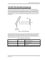
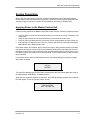
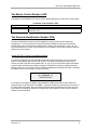
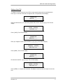
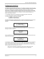
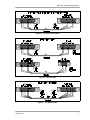
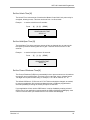
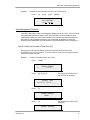
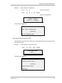
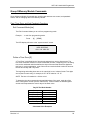
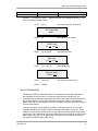
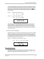
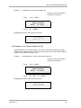
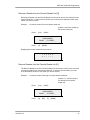
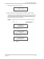
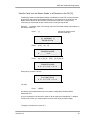
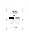
Keri Systems
User Manual
HPP-100
Hand-Held Programmer
HPP-100 Hand-Held Programmer
© 1996 Keri Systems, Inc. ALL RIGHTS RESERVED
Document Number 01817-001, Revision 3.3
September 1999
Keri Systems, HPP-100 Hand-Held Programmer, PXL-100, OB-1, and KMM-40 Memory Module
are trademarks of Keri Systems, Inc. Other product names are trademarks or registered
trademarks of their owners.
Keri Systems reserves the right to change, without notice, product offerings or specifications.
No part of this publication may be reproduced in any form without written permission from Keri
Systems Inc.
Revision 3.3
iii
HPP-100 Hand-Held Programmer
Contents
THE HPP-100 HAND-HELD PROGRAMMER
1
Programming Command Groups
2
System Preparation
Applying Power to the Master Control Unit
The Master Control Reader’s LED
The Personal Identification Number (PIN)
Using the PIN to Enter Programming Mode
Setting a New PIN
Configuring the Serial Port
3
3
4
4
4
5
6
Command Descriptions
Standard Commands
Timing Functions
Set the Date [G]
Set the Time [G]
Set the Unlock Time [N]
Set the Held-Open Time [N]
Set the Close of Business Time [N]
Card Management Functions
Enroll a Card in a Slot and a Time Zone [G]
Enroll Cards in Batch Mode [G]
Void a Card [G]
Voiding Consecutive Cards [G]
Change a Card’s Time Zone [N]
Change the Time Zone for Consecutive Cards [N]
Printing Functions
Verify a Card [G]
Print Transactions [G]
Print Enrolled Cards [G]
Print Status Information [G]
Print the Last nnnn Transactions [G]
Print Cards from a Time Zone [G]
Group 0/Memory Module Commands
Card, Time Zone, and Anti-Passback Functions
Exit Command Mode [n/a]
Define a Time Zone [G]
Set Anti-Passback [N]
Set Auto-Unlock Time Zones [N]
Memory Module Functions
Set the Data File Identifier [n/a]
Transfer Cards to the Memory Module [N]
Transfer Events to the Memory Module [N]
Erase the Memory Module [n/a]
Erase Events in the Memory Module [n/a]
Transfer Cards from the Memory Module [G]
8
9
9
9
9
10
10
10
11
11
12
13
14
14
15
15
15
16
16
17
18
19
20
20
20
20
21
22
22
23
23
24
24
24
25
Contents (continued)
Revision 3.3
iv
HPP-100 Hand-Held Programmer
Level Commands
Serial Port Function
Configure the Serial Port [N]
Manual Card Enrolling Function
Enroll Card by the Number Code [G]
Security Functions
Reset Anti-Passback for All Cards [G]
Set the Card Security Fence [N]
Set Daylight Savings Time [G]
Favorite Reader List Functions
Display the Favorite Reader List [G]
Add a Reader to the Favorite Reader List [G]
Add Readers to the Favorite Reader List [G]
Remove a Reader from the Favorite Reader List [G]
Remove Readers from the Favorite Reader List [G]
Transfer a Card from the Master Reader to all Readers on the FRL [G]
Transfer Cards from the Master Reader to all Readers on the FRL [G]
Master Control Commands
Change a PIN [G]
Clear Reader Memory [N]
25
25
25
26
26
27
27
28
28
29
29
29
30
31
31
32
33
34
34
35
APPENDICES
36
Glossary
38
HPP-100 Hand-Held Programmer Quick Start Guide
39
Customer Support Information
41
Warranty Information
42
Figures
FIGURE 1 – HPP-100 ORIENTATION
FIGURE 2 - THE SERIAL PRINTER CABLE
FIGURE 3 - THE PC CABLE
FIGURE 4 - THE MODEM CABLE
Revision 3.3
1
7
7
7
v
HPP-100 Hand-Held Programmer
Revision 3.3
vi
HPP-100 Hand-Held Programmer
The HPP-100 Hand-Held Programmer
The HPP-100 Hand-Held Programmer is a powerful and convenient tool, yet its operation is
simple enough for anyone to master in a short period of time. The HPP-100 has the appearance
of a TV remote control, but has a different principle of operation. It is a mini-transmitter using a
radio frequency (RF) rather than an infrared signal to transmit data. Unlike a television remote
control (that requires a direct line-of-sight between the infrared transmitter in the remote and the
infrared receiver in the television) the HPP-100 should be held parallel to the proximity antenna
(see Figure 1).
Reader
Hand Held
Programmer
Figure 1 – HPP-100 Orientation
Hold the HPP-100 within the range of the proximity antenna (approximately 1-foot) and press the
appropriate button to send a command. Allow about 0.5 seconds for a response from the reader.
Point it at the Master Control Reader (within three to four inches of the reader) and press the
appropriate button to send a command. Allow about a half-second for a command response. The
reader’s sound alert will respond to the command with a distinct beep.
BEEP
BEEP-BEEP
BEEEEEEEEP
BEEP-BEEP-BEEP-BEEP
Revision 3.3
Command Response “BEEP” Status
1 short
Confirms the depression of a key on the
Hand-Held Programmer.
2 short
Confirms acceptance of a complete
command sequence.
1 long
Confirms rejection or an invalid operation was
attempted.
continuous short
Indicates the door sense switch is open.
1
HPP-100 Hand-Held Programmer
In conjunction with the Hand-Held Programmer, there are three hardware options that can be
used as programming aids.
1. The 32-character LED display is strongly recommended when using the HPP-100 to program
a PXL-100 network or a stand-alone system. The display is standard with the OB-1 option
board, but can be used with any of the plug-in option boards. The display is not necessary if a
Personal Computer (PC) is used as the control system host, but it is a handy troubleshooting
tool that can be plugged into any networked control unit for diagnosing local system problems.
2. A Programming Reader is a second reader connected in parallel with the Master Control
Reader. It is located beside the Master Control Unit to assist in enrolling cards or in
programming the network if a PC is not used.
3. A Serial Printer may be attached to the Master Control Unit, providing printouts of system
configuration information. It will also provide brief printouts confirming the completion of each
programming command.
NOTE: The HPP-100 Hand-Held Programmer is meant for use in networks with less than 8
controllers. In networks with 8 or more controllers, a PC system must be used for programming.
Programming Command Groups
Basic programming commands are broken into four groups:
1) Standard Commands are used for setting system time and date, event timing, card
management, and printing operations.
2) Group 0/Memory Module Commands are used for card and time zone control, anti-passback
control, and for managing data in the Memory Module.
3) Level Commands are used for configuring the serial port, enrolling cards by code number,
transferring cards from a master reader, adding and removing readers, and setting security
features.
4) Master Control Commands are used for changing a user’s Personal Identification Number
(PIN) and for clearing a reader’s memory.
See Appendix 2 for a Quick Start Guide that provides summaries for all programming commands.
Revision 3.3
2
HPP-100 Hand-Held Programmer
System Preparation
When using the Hand-Held Programmer, all system programming is done through the Master
Reader. Before using the Hand-Held Programmer, perform the following system preparation and
verification steps to ensure your system is fully operational and ready for programming.
Applying Power to the Master Control Unit
If power is being applied to the Master Control Unit for the first time, perform the following checks.
•
•
•
•
Verify all power and network communication wiring is correctly and securely connected to the
control units.
Verify all option boards are correctly and securely connected to the control units.
Verify all control unit addresses are set correctly, with a unique address for each control unit.
If the optional LCD display is used, verify it is correctly and securely connected to the Master
Option Board on the Master Control Unit.
Once these checks are complete, apply power to the system. After several seconds of operation,
the network will begin to communicate, and the Network Activity LED (in the upper left corner of
the Master Control Unit’s option board) will pulse in rapid bursts followed by a short pause. If the
LED does not pulse, the network is not communicating. Turn all system power off and review the
above checklist.
If the system has the optional LCD display installed, it will briefly display the following message
when power is applied.
OB-xxx
MASTER
The upper field displays type of option board connected and the lower field displays the mode of
operation (Master, APB Master, or Reader Number).
When the unit completes its power-up sequence, the following message appears and remains on
the LCD display. This is the “system at work” screen.
KERI SYSTEMS
DAY HH : MM : SS
Revision 3.3
3
HPP-100 Hand-Held Programmer
The Master Control Reader’s LED
The Master Control Reader’s LED can be used to identify the Master Control Unit’s current status.
Single Quick Flash
Fast Blinking
Slow Blinking
The Master Control Reader’s LED
confirms an access card was read during normal operation
indicates the Master Control Unit is in the programming mode
indicates the Master Control Unit is set to the enrollment mode (for PC
operation only)
The Personal Identification Number (PIN)
A Personal Identification Number (PIN) is assigned to provide security for the Hand-Held
Programmer. A user must enter the correct PIN before the Master Control Unit will enter the
programming mode. A default PIN is assigned at the factory; the default PIN is [0] [0] [0] [0].
We recommend that you set a unique PIN as soon as possible to ensure the security of your PXL100 access control system.
Using the PIN to Enter Programming Mode
To enter the programming mode, point the Hand-Held Programmer within 3 to 5 inches of the
Master Control Reader and enter the PIN number. The very first time programming mode is
entered, the PIN will be the factory default PIN: [0] [0] [0] [0]. If the PIN is accepted, the Master
Control Reader’s LED will pulse quickly indicating commands can now be programmed into the
Master Control Unit. The optional LCD (if installed) will display the following information, indicating
the Master Control Unit is ready to accept commands.
[h] COMMAND [1]
ENTER OPTION
If the PIN is not accepted, the Master Control Reader’s LED will not pulse and the reader will
respond with a command rejected ‘NO-BEEP.’ Press the CLEAR key and repeat the command. If
the PIN is still not accepted, this may mean the PIN has been changed and will need to be reset.
Instructions for resetting the PIN can be obtained from Keri Systems. Please contact Customer
Support for this information.
Revision 3.3
4
HPP-100 Hand-Held Programmer
Setting a New PIN
To assign a new PIN, enter the current PIN to enter programming mode as described above.
Press [9] to enter the command to change the PIN. The optional LCD will display:
CHANGE PIN
OLD PIN _ _ _ _
Enter the old PIN value. (If it is the factory default PIN, it will be [0] [0] [0] [0].) The LCD will
display:
[VOID] [CLEAR]
OLD PIN x x x x
Press [VOID]. The LCD will display:
CHANGE PIN
NEW PIN _ _ _ _
Enter your 4 digits to make up the new PIN: [x] [x] [x] [x]. The LCD will display:
[ENROLL] [CLEAR]
NEW PIN x x x x
Press [ENRL]. The LCD will display:
CHANGE PIN
NEW PIN _ _ _ _
Re-enter the new PIN: [x] [x] [x] [x]. The LCD will display:
[SEND] [CLEAR]
NEW PIN x x x x
Press [SEND] to complete the command. The Master Control Unit will now respond to the new
PIN.
Revision 3.3
5
HPP-100 Hand-Held Programmer
Configuring the Serial Port
To establish communication with a serial printer, PC, or Modem, the Master Control Unit’s serial
port must be configured for the device to be used. To configure the serial port for the serial printer
or the PC, the serial printer or PC cabling at the Master Control Unit’s serial port must be
disconnected. To configure the serial port for the modem, the modem must be connected and
ready to receive initialization string from the Master Control Unit. The serial printer or PC cabling
can be reconnected after the Serial Port is configured. Use the Hand-Held Programmer to
perform the following commands.
1) If the Master Control Unit is not already in the programming mode, enter the PIN.
2) Press [LVL] [9] [2] to enter the ‘set serial port’ mode.
3) Press [0] [SEND] for Serial Printer operation,
[1] [SEND] for PC operation, or
[2] [SEND] for Modem operation.
The optional LCD display (if installed) will assist in monitoring command status as you enter this
information. For example, beginning with Step 2 from above, the following information is
displayed.
SERIAL PORT
PRT = 0 PC = 1 REM = 2
And as the selection is made for step 3 from above (for example 0, for the Serial Printer), the
following information is displayed.
SERIAL PORT
PRINTER
When the [SEND] key is pressed, the command is executed and the Master Control Unit is now
ready for the next command.
[p] COMMAND [1]
ENTER OPTION
In this “Ready for Command” screen, the field in the upper left corner indicates the configuration
of the serial port: [p] for the Serial Printer, [h] for host PC or Memory Module, and [m] for the
Modem. These characters will be in lower-case when the communication line is “off-line” and in
upper case when the communication line is “on-line.”
NOTE: Each communication configuration requires unique cabling. Please refer
to Figures 2, 3, and 4 to determine the cabling required for your application.
Revision 3.3
6
HPP-100 Hand-Held Programmer
Figure 2 - The Serial Printer Cable
Figure 3 - The PC Cable
Figure 4 - The Modem Cable
Revision 3.3
7
HPP-100 Hand-Held Programmer
Command Descriptions
This section provides descriptions and usage instructions for every command that is available for
the Hand-Held Programmer. Before using any command, the Master Control Unit must be in the
programming mode. This is done by entering your PIN as described in the Setting a New PIN
section listed above.
The following notes apply to every command described in this document.
1. When pressing keys, please remember the following:
•
•
•
1 short BEEP confirms the depression of a key on the Hand-Held
Programmer.
2 short BEEPs confirm the acceptance of a complete command.
1 long BEEP confirms the rejection of a command or that an invalid operation
was attempted.
2. While not in programming mode:
•
•
Pressing [LVL] toggles Monitor Mode ON and OFF.
Pressing [SND] toggles the LCD display through system status screens (time,
date, software version, responding readers).
3. To cancel a command at any time during command entry, press [CLR].
4. Commands can be applied to either an individual Control Unit/Reader or to all Control
Units/Readers on the Favorite Reader List (FRL).
•
•
•
To select a specific Reader, press [LVL] followed by the Reader number (18). The Reader number will appear in the upper-right field of the LCD display.
To select all readers on the FRL, press ZIP (an * will appear in the upperright field of the LCD display.
To configure the FRL see the instructions for adding a Reader or Readers to
the FRL in the Level Commands section below.
5. Some commands apply to the Master Control Unit and all slave units on the network.
These are “Global” commands, and are identified by a [G] beside the command’s title.
The balance of the commands are “Non-global” commands, and are identified by a
[N] beside the command’s title. These commands apply to only the readers on the
FRL or can be directed to a specific reader as described in item 4, above.
6. All time commands are formatted to a 24-hour clock – for example, 6:15 P.M. is
coded as 18:15.
7. For serial printer commands, sample printouts are included in the descriptions as
applicable. If the serial printer is connected and on-line during the execution of a
programming command, a summary of the command’s results is printed upon
command completion.
8. If the optional LCD display is installed, it will display prompting messages for the
command in progress. Sample LCD displays are included in the descriptions as
applicable.
9. The Hand-Held Programmer can program slot numbers 0000 through 6999 and time
zones 0 through 7 (except for time zone 6). Time zone 0 is used to disable time zone
Revision 3.3
8
HPP-100 Hand-Held Programmer
checking for that card, allowing free access at any time. Time zones 1 through 5 are
user programmable. Time zone 6 is reserved for network use. Time zone 7 is used to
disable time zone access for a card (called the “Never” time zone).
NOTE: When using a PC host system for programming, you can program a greater
number of time zones to provide a greater degree of flexibility.
Standard Commands
Standard Commands are used for setting system time and date, event timing, card management,
and printing operations.
Timing Functions
Set the Date [G]
The Date is set in a two digit, month / day / year format. Two digits are required for each
entry; for example, the month of July is coded as ‘07’ and the fourth day is coded as ‘04.’
Example . . . to set the date as July 4, 1995:
Press . . . [7]
[0] [7]
[0] [4]
[9] [5]
[SEND]
SYSTEM DATE
M: 0 7 D: 0 4 Y: 9 5
Set the Time [G]
The Time is set in a two digit, hours / minutes format. Two digits are required for each
entry; for example, 7:15 A.M. is coded as ‘07’ ‘15.’
Example . . . to set the time as 7:15 P.M.:
Press . . . [8]
[1] [9]
[1] [5]
[SEND]
SYSTEM TIME
H: 1 9 M: 1 5
Revision 3.3
9
HPP-100 Hand-Held Programmer
Set the Unlock Time [N]
The Unlock Time is the amount of time that the Master Control Unit’s lock power relay is
energized, allowing access. This time can be set from 1 to 99 seconds.
Example . . . to set the unlock time to 5 seconds:
Press . . . [4]
[0] [5]
[SEND]
DOOR UNLOCK TIME
SECS: 0 5
Set the Held-Open Time [N]
The Held-Open Time is the maximum amount of time an alarmed door or gate may be
held open by someone entering that door or gate. This time can be set from 1 to 99
seconds.
Example . . . to set the held-open time to 10 seconds:
Press . . . [5]
[1] [0]
[SEND]
DOOR OPEN TIME
SECS: 1 0
Set the Close of Business Time [N]
The Close of Business (COB) time automatically locks or prevents access to a location at
one specific time on a daily basis. This time is set in a two digit, hours / minutes format.
Two digits are required for each entry; for example, 7:15 A.M. is coded as ‘07’ ‘15.’
The default COB time is 17:00 hours or 5 P.M. This time should be changed, as needed,
to meet your application. We recommend always having a COB time programmed to
avoid the possibility of leaving an access point open or unlocked.
If your application will not use the COB feature, it can be disabled by entering a time of
00:00 hours. If your application requires setting the COB to 24:00 hours (Midnight), enter
a time of 23:59 or 00:01 (one minute before or one minute after Midnight).
Revision 3.3
10
HPP-100 Hand-Held Programmer
Example . . . to set the close of business time to 6 P.M. (18:00 hours):
Press . . . [6]
[1] [8]
[0] [0]
[SEND]
SET COB TIME
H: 1 8 M: 0 0
Card Management Functions
In the PXL-100 system, cards are managed by assigning them to a “Slot.” A slot is a list of
information that applies to a specific card. The information in a slot includes the slot’s
identification number, the card’s unique number code, and the time zone that applies to
that card. (In a PC programmed system, more information is applied to a card’s slot,
allowing for the identification and categorization of the individual the card is assigned to.)
Enroll a Card in a Slot and a Time Zone [G]
Enrolling a Card through the Master Control Unit provides the card with access
authorization to the security system. To enroll a card you must have an empty slot and a
time zone to assign the card.
Example . . . to enroll a card into slot 47, time zone 2:
Press . . . [ENRL]
ENROLL CARD[S]
#: _ _ _ _ TO #: _ _ _ _
Press . . . [0] [0] [4] [7]
(the empty slot number where
the card is to be enrolled)
[LEVEL] [ZIP]
#: 0 0 4 7 TO #: _ _ _ _
Press . . . [L]
ENROLL CARD[S]
LEVEL: _
Press . . . [2]
(the time zone the card is to be
assigned)
[SEND]
Revision 3.3
[CLEAR]
11
HPP-100 Hand-Held Programmer
LEVEL: 2
Press . . . [SEND]
PRESENT CARD[S]
ENROLLING 0 0 4 7
Present the card to the Master Reader and the reader responds with two short-BEEPs
that signify the command is complete.
Notes on Card Enrollment:
1. Attempting to enroll a card in an occupied slot will cause the program to exit, requiring
reentering the PIN and beginning again. Attempting to enroll a card that is already
enrolled will produce a “NO-BEEP,” but will hold the program until a valid (unenrolled)
card is presented.
2. For ease of card/slot management, you should consider marking each card with the
slot number you have assigned to it. This can make it easier for you to work with the
cards within the system.
3. When cards are enrolled in the Master Control Unit, they are also enrolled in all slave
units. Slaves on the FRL will take on the programmed time zone value, slaves not on
the FRL will take on the “Never” time zone access value.
Enroll Cards in Batch Mode [G]
Enrolling cards in Batch Mode is similar to entering a single card. There must be one
empty slot per card, the slots must be in consecutive order, and one time zone must be
selected for all of the cards to follow (each card entered in batch mode will be assigned to
the same time zone).
Example . . . to enroll a batch of cards into slots 10 through 20, time zone 2:
Press . . . [ENRL]
ENROLL CARD[S]
#: _ _ _ _ TO #: _ _ _ _
Press . . . [0] [0] [1] [0]
[ZIP]
[0] [0] [2] [0]
(the beginning slot number to
the ending slot number - all
empty slots)
[LEVEL] [ZIP]
#: 0 0 1 0 TO #: 0 0 2 0
Revision 3.3
12
HPP-100 Hand-Held Programmer
Press . . . [L]
ENROLL CARD[S]
LEVEL: _
Press . . . [2]
(the time zone for all cards in
the batch to follow)
[SEND] [CLEAR]
LEVEL: 2
Press . . . [SEND]
PRESENT CARD[S]
ENROLLING 0 0 1 0
Present each card to the Master Reader one at time. With each correct entry, the reader
will respond with a two short BEEPs signifying the card was accepted. If a slot is occupied
or the card is already enrolled, the response will be a “NO-BEEP.”
Void a Card [G]
Voiding a Card removes it from the Master Control Unit’s list of occupied slots. To void a
card you must know the card’s slot number. You do not have to have the card in hand to
void it from the Master Control Unit.
Example . . . to void the card in slot 47:
Press . . . [VOID]
VOID CARD[S]
#: _ _ _ _ TO #: _ _ _ _
Press . . . [0] [0] [4] [7]
(the slot number)
VOID CARD[S]
#: 0 0 4 7 TO #: _ _ _ _
Press . . . [SEND]
Revision 3.3
13
HPP-100 Hand-Held Programmer
Voiding Consecutive Cards [G]
Voiding Cards removes them from the Master Control Unit’s list of occupied slots. Voiding
cards in Batch Mode is similar to voiding a single card. You must know the slot number
assigned to each card. You do not have to have the cards in hand to void them from the
Master Control Unit.
Example . . . to void a batch of cards in slots 10 through 20:
Press . . . [VOID]
VOID CARD[S]
#: _ _ _ _ TO #: _ _ _ _
Press . . . [0] [0] [1] [0]
[ZIP]
[0] [0] [2] [0]
(the beginning slot number to
the ending slot number)
VOID CARD[S]
#: 0 0 1 0 TO #: 0 0 2 0
Press . . . [SEND]
Change a Card’s Time Zone [N]
Changing a Card’s Time Zone allows a card’s time zone to be changed to a new value.
You must know the slot number for the card to be changed.
Example . . . to change card 1012 to time zone 3:
Press . . . [3]
[1] [0] [1] [2]
CHANGE LEVEL
#: 1 0 1 2 TO #: _ _ _ _
Press . . . [LVL]
[3]
[SEND]
CHANGE LEVEL
LEVEL: 3
Revision 3.3
14
HPP-100 Hand-Held Programmer
Change the Time Zone for Consecutive Cards [N]
Changing the Time Zone for Consecutive Cards allows the time zone for consecutive
cards to be changed to a new value. You must know the slot numbers for the cards to be
changed and they must be consecutive slot numbers.
Example . . . to change the time zone for consecutive cards in slots 10 through 20 to time
zone 2:
Press . . . [3]
CHANGE LEVEL
#: _ _ _ _ TO #: _ _ _ _
Press . . . [0] [0] [1] [0]
[ZIP]
[0] [0] [2] [0]
(the beginning slot number to
the ending slot number - all
for the new time zone)
[LEVEL] [ZIP]
#: 0 0 1 0 TO #: 0 0 2 0
Press . . . [LVL]
CHANGE LEVEL
LEVEL: _
Press . . . [2]
(the time zone for all cards in
the batch to follow)
[SEND]
[CLEAR]
LEVEL: 2
Press . . . [SEND]
Printing Functions
NOTE: All printing commands assume a serial printer is connected to the Master Control
Unit.
Verify a Card [G]
Revision 3.3
15
HPP-100 Hand-Held Programmer
Verifying a Card sends the card’s internal code number and the time zone that card has
been assigned to the serial printer.
Example . . . to verify the card in slot 2139:
Press . . . [1]
[2] [1] [3] [9]
CARD VALIDATION
SLOT#: 2 1 3 9
The printout will appear as:
CARD VALIDATION FOR SLOT 2139
CODE NUMBER: 0 1 2 3 4 5 6 7 8 9
TIME ZONE: 01
Print Transactions [G]
Printing Transactions sends a list of all transactions (programming, alarm, access, or
egress) occurring at the Master Control Unit to the serial printer.
Example . . . to print transactions:
Press . . . [0]
[0]
[SEND]
PRINT EVENTS
[SEND] [CLEAR]
The printout will appear as:
ALL TRANSACTIONS FOR DOOR [ID#]
DATE TIME TRANSACTION
(continued)
END OF TRANSACTIONS
Print Enrolled Cards [G]
Printing Enrolled Cards sends a list of all cards (by slot number) which are enrolled in the
Master Control Unit to the serial printer.
Revision 3.3
16
HPP-100 Hand-Held Programmer
Example . . . to print enrolled cards:
Press . . . [2]
[#]
[SEND]
PRINTER
[SEND] [LEVEL]
The printout will appear as:
ENROLLMENT FOR DOOR [ID#] LEVEL
(beginning card slot number)
(continued)
(ending card slot number)
[total] Cards
Print Status Information [G]
Printing Status Information sends a list of the Master Control Unit’s status to the serial
printer.
Press . . . [2]
[#]
Revision 3.3
[0]
[SEND]
PRINTER
[SEND] [LEVEL]
17
HPP-100 Hand-Held Programmer
The printout will appear as:
SYSTEM INFORMATION FOR DOOR: [ID#]
Firmware Rev: [rev #]
Option Board: [option board type]
Time: [xx:xx]
Date: [day-of-week MM-DD-YY]
System ID: [xx]
Cold Reset: [number that have occurred]
Warm Reset: [number that have occurred]
POST Errors: [number that have occurred]
Local APB: [anti-passback status ON/OFF]
Open time: [time or OFF]
Unlock time: [time or OFF]
COB time: [time or OFF]
Auto-Unlock: [time or OFF]
Capacity Trip: [value or OFF]
Security Fence: [value or OFF]
Daylight Savings: [ON or OFF]
TIMEZONES:
TZ0: [current status]
through
TZ15: [current status]
(continued next page)
HOLIDAYS:
[current status]
DATABASE:
# Transactions: xxx
# Cardholders: xx
# Temporaries: xx
Print the Last nnnn Transactions [G]
Printing the Last nnnn Transactions sends a list of the last nnnn (a user defined quantity)
transactions (programming, alarm, access, or egress) that occurred at the Master Control
Unit to the serial printer.
Revision 3.3
18
HPP-100 Hand-Held Programmer
Example . . . to print the last 10 transactions:
Press . . . [2]
[1]
Press . . . [0]
[0]
(the print command)
[1]
[0]
[SEND]
(the last 10 transactions)
[SEND] [CLEAR]
LAST 0 0 1 0 EVENTS
The printout will appear as:
LATEST TRANSACTIONS FOR DOOR [ID#]
DATE TIME TRANSACTION
(continued)
END OF TRANSACTIONS
Print Cards from a Time Zone [G]
Printing Cards from a Time Zone allows you to list the cards that are valid for a given time
zone by slot number.
Example . . . to print cards from a given time zone:
Press . . . [2]
[LVL]
[TZ#]
[SEND]
PRINT ENROLLMENT
LEVEL: __
The printout will appear as:
ENROLLMENT FOR DOOR [ID#] LEVEL
(beginning card slot number)
(continued)
(ending card slot number)
[total] Cards
Revision 3.3
19
HPP-100 Hand-Held Programmer
Group 0/Memory Module Commands
Group 0/Memory Module Commands are used for card and time zone control, anti-passback
control, and for managing data in the Memory Module.
Card, Time Zone, and Anti-Passback Functions
Exit Command Mode [n/a]
The Exit Command allows you to exit from programming mode.
Example . . . to exit from programming mode:
Press . . . [0]
[SEND]
The LED display will return to the “system at work” screen.
KERI SYSTEMS
DAY HH : MM : SS
Define a Time Zone [G]
A Time Zone is a defined block of time that is assigned to a card to allow access. The
time zone command consists of a zone identification number, a beginning time, an ending
time, and a calculated value that defines the days of the week that should be applied to
this zone. In a given application, a set of time zones must be defined to take into account
the full 24-hour day and 7-day week.
The beginning and ending times are set in a two digit, hours / minutes format. Two digits
are required for each entry; for example, 6:15 P.M. is coded as ‘18’ ‘15.’
NOTE: The time is formatted to a 24-hour clock.
To determine the value representing the applicable days of the week, each day of the
week is assigned a number (see the Table below). These numbers are added together
and the result represents the zone’s days of the week value.
Day Of The Week Number
Sunday
Monday
Tuesday
Wednesday
Thursday
Friday
Saturday
=1
=2
=4
=8
= 16
= 32
= 64
Calculated Value Examples
Revision 3.3
20
HPP-100 Hand-Held Programmer
Saturday and Sunday
64 + 1 = 65
Monday through Friday
2+ 4 + 8 + 16 + 32 = 62
7-Days
1 + 2 + 4 + 8 + 16 + 32 + 64 = 127
Example . . . to create time zone 1 – beginning at 8:00 A.M., ending at 5:00 P.M. (17:00
hours), for Monday through Friday:
Press . . . [0] [1]
(the create time zone command)
SET TIME ZONE
ZONE: _
Press . . . [1]
(the desired zone number)
START TIME
H: x x M: x x
Press . . . [0] [8] [0] [0]
(the beginning time)
END TIME
H: x x M: x x
Press . . . [1] [7] [0] [0]
(the ending time)
DAYS OF WEEK
CODE: x x x
Press . . . [0] [6] [2]
(the days of the week value)
Press . . . [SEND]
Set Anti-Passback [N]
The Set Anti-Passback command enables or disables the local anti-passback feature.
Anti-passback is used to ensure one-card/one-way access into and then out of a
controlled area. An authorized card presented to the access reader will allow access, but
will not work again for access until presented to the egress reader, or until either the
Master Control Unit is reset with the Reset Anti-Passback command (described below) or
24 hours have passed.
There are two types of anti-passback operations: local and networked. For local antipassback operation, two readers must be connected to the Master Control Unit. These
readers are connected in parallel to TB-3 on the control unit except for the reader’s blue
signal leads. The signal lead for the access reader must be connected to the control unit’s
ANT-A input (TB-3, Pin 5). The signal lead for the egress reader must be connected to
the control unit’s ANT-B input (TB-3, Pin 6).
Revision 3.3
21
HPP-100 Hand-Held Programmer
For networked anti-passback, two to eight control units may be networked. One control
unit must be designated as the Master Control Unit and must be equipped with a Master
Option Board. The Master Option Board must have address switches 7 and 8 ON. This
unit will be the only access reader. The remaining control units must be equipped with
Slave Option Boards. All of these units must have unique addresses set. These units will
be egress readers.
Example . . . to enable the anti-passback mode:
Press . . . [0]
[3]
[1]
[SEND]
Example . . . to disable the anti-passback mode:
Press . . . [0]
[3]
[0]
[SEND]
SINGLE DOOR APB
[0] = OFF [1] = ON
Please Note: When in a local anti-pass back application (but not in a networked antipassback application), to support situations where a user presents a valid card but
decides not to enter or is delayed entering, the system does not impose anti-passback
checking until the user actually opens the door to enter. If the user does not open the
door, the same card can be presented again to the reader without being considered an
anti-passback violation.
Set Auto-Unlock Time Zones [N]
Setting the Auto-Unlock Time Zones provides automatic unlocking of a door or controlled
access area according to the “open” time of the time zones. Up to two auto-unlock time
zones can be assigned. In a standard application, the first time zone corresponds to a
typical Monday through Friday work week. The second time zone would provide flexibility
for weekend hours. The default value for both time zones is ‘07,’ representing the ‘Never”
time zone which disables the auto-unlock feature.
Example . . . to set the auto-unlock time zones to 1 and 2:
Press . . . [0]
[4]
[1] [8]
[0] [0]
[SEND]
AUTO UNLOCK
TZ: 0 1 TZ: 0 2
Memory Module Functions
The KMM-40 Memory Module is a device that is used to transfer data between Control
Units when there is no direct connection between the units. The Memory Module has 32
Kbytes of non-volatile memory for storing card and event data.
Revision 3.3
22
HPP-100 Hand-Held Programmer
Set the Data File Identifier [n/a]
Setting the Data File Identifier allows you to assign a file name to the data being loaded
into the Memory Module.
Example . . . to set a data file identifier of 1 2 3:
Press . . . [0]
[7]
ID: x x x
ID: _ _ _
Press . . . [1] [2] [3]
SET SYSTEM ID
ID: 1 2 3
Press . . . [SEND]
Transfer Cards to the Memory Module [N]
Transferring Cards to the Memory Module allows you transfer card data from a Control
Unit to the Memory Module for transfer to another Control Unit or a PC system.
Example . . . to transfer cards to the memory module:
Press . . . [0]
[2]
[SEND]
(allow time for the data to
transfer)
DUMP CARD DATA
[SEND] [CLEAR]
Revision 3.3
23
HPP-100 Hand-Held Programmer
Transfer Events to the Memory Module [N]
Transferring Events to the Memory Module allows you transfer event data from a Control
Unit to the Memory Module for transfer to another Control Unit or a PC system.
Example . . . to transfer events to the memory module:
Press . . . [0]
[5]
[SEND]
(allow time for the data to
transfer)
DUMP EVENT LOG
[SEND] [CLEAR]
Erase the Memory Module [n/a]
Erasing the Memory Module allows you to erase data from the Memory Module to free it
for use again.
Example . . . to erase the memory module:
Press . . . [0]
[6]
[VOID]
ERASE MEM MODULE
[VOID] [CLEAR]
Erase Events in the Memory Module [n/a]
Erasing Events in the Memory Module allows you to erase event data from the memory
module to free it for use again.
Example . . . to erase event data in the memory module:
Press . . . [0]
[8]
[SEND]
ERASE EVENT LOG
[SEND] [CLEAR]
Revision 3.3
24
HPP-100 Hand-Held Programmer
Transfer Cards from the Memory Module [G]
Transferring Cards from the Memory Module allows you transfer card data from the
Memory Module to a PXL-100 control unit. You must know the ID number of the data file
you wish to transfer.
Example . . . to transfer cards from data file identifier 1 2 3 in the memory module:
Press . . . [0]
[VOID]
LOAD CARD DATA
ID: _ _ _
Press . . . [1] [2] [3]
LOAD CARD DATA
[SEND] [CLEAR]
Press . . . [SEND]
(allow time for the data to
transfer)
Level Commands
Level Commands are used for configuring the serial port, manually enrolling a card by code
number, setting security features, and managing the Favorite Reader List.
Serial Port Function
Configure the Serial Port [N]
Configuring the Serial Port establishes communication between the Master Control Unit
and either a serial printer, a PC, or a Modem. To configure the serial port for the serial
printer or the PC, the serial printer or PC cabling at the Master Control Unit’s serial port
must be disconnected. To configure the serial port for the modem, the modem must be
connected and ready to receive initialization string from the Master Control Unit. The
serial printer or PC cabling can be reconnected after the Serial Port is configured.
Revision 3.3
25
HPP-100 Hand-Held Programmer
Example . . . to configure the serial port:
Press . . . [LVL]
[9]
[2]
SERIAL PORT
PRT = 0 PC = 1 REM = 2
For serial printer operation,
Press . . . [0]
[SEND]
For PC operation,
Press . . . [1]
[SEND]
For modem operation,
Press . . . [2]
[SEND]
SERIAL PORT
PRINTER or PC or MODEM
(the appropriate serial port
status will be displayed)
NOTE: Each communication configuration requires unique cabling. Please refer
to Figures 1, 2, and 3 (given above) to determine the cabling required for your
application.
Manual Card Enrolling Function
Enroll Card by the Number Code [G]
Enrolling a Card by the Number Code is used to manually enroll a card when you do not
physically have the card in hand. To perform this command, you must know the card’s
internal code number and the slot number you wish the card to be in.
Example . . . to enroll a card with internal code number 0 0 7 9 3 3 4 2 7 4 into slot
number 17:
Press . . . [LVL]
[9]
[4]
MANUAL ENROLL
SLOT # : _ _ _ _
Press . . . [0] [0] [1] [7]
ENTER CODE
Revision 3.3
26
HPP-100 Hand-Held Programmer
_ _ _ _ _ _ _ _ _ _
Press . . . [0] [0] [7] [9] [3] [3] [4] [2] [7] [4]
[LVL] [SND] [CLR]
0 0 7 9 3 3 4 2 7 4
At this point, you have a choice.
You may . . .
Press . . . [SEND]
and all the default card/slot time zone and system configuration attributes will be
transferred as is.
Or you may assign a time zone value for the card being entered. To assign a time zone
value, you must know the time zone value you wish to apply.
To assign a time zone value of 3:
Press . . . [LVL]
ENTER CODE
LEVEL : _
Press . . . [3]
[SEND]
Security Functions
Reset Anti-Passback for All Cards [G]
Anti-passback is used to ensure one-card/one-way access into and then out of a
controlled area. An authorized card presented to the access reader will allow access, but
will not work again for access until one of three things happens: the card has been
presented to an egress reader, 24 hours have passed, or the Master Control Unit has
been reset with the Reset Anti-Passback command. The Reset Anti-Passback for All
Cards command resets the passback status for all cards in the system. This will allow a
card previously considered inside the access area to be reused for access once.
Revision 3.3
27
HPP-100 Hand-Held Programmer
Example . . . to reset the anti-passback mode for all access cards:
Press . . . [LVL]
[9]
[0]
[SEND]
APB AMNESTY
[SEND] [CLEAR]
Set the Card Security Fence [N]
The Card Security Fence feature allows cards to be used to remotely arm or disarm an
alarm panel. To set the security fence, a slot number is designated to be a boundary
between “privileged” and “non-privileged” cards. Cards at or below this number become
privileged cards, cards that are above this number become non-privileged cards.
Privileged cards can then be used to remotely control an alarm panel. Non-privileged
cards can still be granted access, but will cause an alarm event if a privileged card has
armed the alarm panel. Please refer to the manual for the OB-3 Input/Output and Alarm
Panel Control Option Board for hardware implementation information. The factory default
value is card/slot 0, disabling this feature.
Example . . . to set the card security fence for card/slot 100:
Press . . . [LVL]
[9]
[6]
(the LCD displays the current
value)
AT: 0 0 0 0
AT: _ _ _ _
Press . . . [0] [1] [0] [0]
[SEND] [CLEAR]
AT: 0 1 0 0
Press . . . [SEND]
Set Daylight Savings Time [G]
Setting Daylight Savings Time is used to enable or disable the one-hour daylight savings
time change in the Master Control Reader’s clock.
Revision 3.3
28
HPP-100 Hand-Held Programmer
Example . . . to enable daylight savings time:
Press . . . [LVL]
[9]
[7]
[1]
DAYLIGHT SAVINGS
[0] = OFF [1] = ON
Favorite Reader List Functions
The Favorite Reader List is a list of readers on the access control network that are
programmed to be treated equally. Although all readers may be networked together,
programming commands that directed to readers on the favorite reader list affect all
readers on the list; programming commands directed to an independent reader (one not
on the favorite reader list) affect only that reader.
Display the Favorite Reader List [G]
The Display the Favorite Reader List command is used to display those readers that are
tied together on the favorite reader list versus those readers that are independent. All
readers will be listed by reader ID number; those on the favorite reader list will be
identified by a ‘+’ symbol.
Example . . . to view the favorite reader list:
Press . . . [LVL]
[9]
[1]
(this shows there are 6 readers
on this network, addressed as 1
through 6)
1 2 3 4 5 6
+ + – – – –
(and that only readers 1 and 2
are on the favorite reader list)
Add a Reader to the Favorite Reader List [G]
Adding a Reader to the Favorite Reader List is used to add one reader to the favorite
reader list. To perform this command, you must know the address number of the reader
you wish to add.
Revision 3.3
29
HPP-100 Hand-Held Programmer
Example . . . to add reader 4 to the favorite reader list:
(readers 1 and 2 are already on
the favorite reader list)
Press . . . [LVL]
[ENRL]
ENROLL DOOR[S]
DOOR: _ TO DOOR: _
Press . . . [4]
[SEND]
Displaying the favorite reader list will now show:
1 2 3 4 5 6
+ + – + – –
Add Readers to the Favorite Reader List [G]
Adding Readers to the Favorite Reader List is used to add several consecutive readers
together on the favorite reader list. To perform this command, you must know the address
numbers of the readers you wish to add.
Example . . . to add readers 4, 5, and 6 to the favorite reader list:
(readers 1 and 2 are already on
the favorite reader list)
Press . . . [LVL]
[ENRL]
ENROLL DOOR[S]
DOOR: _ TO DOOR: _
Press . . . [4]
[ZIP]
[6]
[SEND]
Displaying the favorite reader list will now show:
1 2 3 4 5 6
+ + – + + +
Revision 3.3
30
HPP-100 Hand-Held Programmer
Remove a Reader from the Favorite Reader List [G]
Removing a Reader from the Favorite Reader List is used to remove one reader from the
favorite reader list. To perform this command, you must know the address number of the
reader you wish to remove.
Example . . . to remove reader 2 from the favorite reader list:
(readers 1 and 2 are already on
the favorite reader list)
Press . . . [LVL]
[VOID]
VOID DOOR[S]
DOOR: _ TO DOOR: _
Press . . . [2]
[SEND]
Displaying the favorite reader list will now show:
1 2 3 4 5 6
+ – – – – –
Remove Readers from the Favorite Reader List [G]
The Remove Readers from the Favorite Reader List command is used to remove several
consecutive readers from the favorite reader list. To perform this command, you must
know the address number of the reader you wish to remove.
Example . . . to remove readers 4 through 6 from the favorite reader list:
(readers 1, 2, and 4 through 6
are already on the favorite
reader list)
Press . . . [LVL]
[VOID]
VOID DOOR[S]
DOOR: _ TO DOOR: _
Press . . . [4]
Revision 3.3
[ZIP]
[6]
[SEND]
31
HPP-100 Hand-Held Programmer
Displaying the favorite reader list will now show:
1 2 3 4 5 6
+ + – – – –
Transfer a Card from the Master Reader to all Readers on the FRL [G]
Transferring a Card from the Master Reader to all Readers on the FRL is used to transfer
all time zone and system configuration attributes for one card from the Master Control
Unit to all other readers on the favorite reader list. To perform this command, you must
know the slot number of the card you wish to add.
Example . . . to transfer card 12 from the master reader to all readers on the favorite
reader list:
Press . . . [*]
(selects all readers on the
favorite reader list)
[h] COMMAND [*]
ENTER OPTION
Press . . . [LVL]
[9]
[3]
TRANSFER CARDS
#: _ _ _ _ TO #: _ _ _ _
Press . . . [0] [0] [1] [2]
TRANSFER CARDS
#: 0 0 1 2 TO #: _ _ _ _
Press . . . [SEND]
Revision 3.3
32
HPP-100 Hand-Held Programmer
Transfer Cards from the Master Reader to all Readers on the FRL [G]
Transferring Cards from the Master Reader to all Readers on the FRL is used to transfer
all time zone and system configuration attributes for a continuous set of cards from the
Master Control Unit to all other readers on the favorite reader list. To perform this
command, you must know the slot numbers of the cards you wish to add.
Example . . . to transfer cards 100 through 200 from the master reader to all readers on
the favorite reader list:
Press . . . [*]
(selects all readers on the
favorite reader list)
[h] COMMAND [*]
ENTER OPTION
Press . . . [LVL]
[9]
[3]
TRANSFER CARDS
#: _ _ _ _ TO #: _ _ _ _
Press . . . [0] [1] [0] [0]
[ZIP]
[0] [2] [0] [0]
TRANSFER CARDS
#: 0 1 0 0 TO #: 0 2 0 0
At this point, you have a choice.
[LVL] [SND] [CLR]
#: 0 1 0 0 TO #: 0 2 0 0
You may . . .
Press . . . [SEND]
and all the current card/slot time zone and system configuration attributes will be
transferred as is.
Or you may assign a new time zone value for all the cards to be transferred. To assign a
new time zone value, you must know the new time zone value you wish to apply.
To assign a new time zone value of 3:
Revision 3.3
33
HPP-100 Hand-Held Programmer
Press . . . [LVL]
TRANSFER CARDS
NEW LEVEL : _
Press . . . [3]
[SEND]
There will be a short delay as the card/slot time zone and system configuration attributes
are transferred from the Master Control Unit to all readers on the favorite reader list. As
the transfer is taking place, the LCD will display the following information.
[P] COMMAND [+]
0 2 0 0 > 6 DOOR[S]
(this shows that up to card/slot
200 is being transferred to 6
readers on the favorite reader
list)
Master Control Commands
Master control commands are fundamental commands used for securing and initializing the
Master Control Unit.
Change a PIN [G]
To ensure Master Control Unit programming security, the PIN may be changed at the
user’s discretion.
Example . . . to change the PIN from the factory default value of 1234 to 1156:
Press . . . [9]
CHANGE PIN
OLD PIN _ _ _ _
Press . . . [1] [2] [3] [4]
[VOID] [CLEAR]
OLD PIN * * * *
Press . . . [VOID]
CHANGE PIN
Revision 3.3
34
HPP-100 Hand-Held Programmer
NEW PIN _ _ _ _
Press . . . [1] [1] [5] [6]
[ENROLL] [CLEAR]
NEW PIN * * * *
Press . . . [ENRL]
CHANGE PIN
NEW PIN _ _ _ _
Press . . . [1] [1] [5] [6]
[SEND] [CLEAR]
NEW PIN * * * *
Press . . . [SEND]
The Master Control Unit will now respond to the new PIN.
Clear Reader Memory [N]
Clearing Reader Memory completely erases all card/slot and event information and
restores the Master Control Unit to all of its factory default values. This command should
be used if the need arises to completely reprogram the system’s access control data.
Example . . . to clear reader memory:
Press . . . [0]
[999]
[SEND]
[999]
[SEND]
SYSTEM RESET
[SEND] [CLEAR]
If the serial printer is connected to the Master Control Unit, the Print Status Information
command will be executed immediately following the Clear Reader Memory command.
The Print Status Information command was described above in the Printing Functions
section.
Revision 3.3
35
HPP-100 Hand-Held Programmer
Appendices
1.
2.
3.
4.
Glossary of Terms
HPP-100 Hand-Held Programmer Quick Start Guide
Customer Support Information
Warranty Information
Revision 3.3
36
HPP-100 Hand-Held Programmer
Revision 3.3
37
HPP-100 Hand-Held Programmer
Glossary
anti-passback — Ensures one-card/one-way access into and then out of a controlled area. An
authorized card presented to the access reader will allow access, but will not work again
for access until presented to the egress reader.
card — A small electro-mechanical device that has a unique electro-magnetic signature. Cards
are programmed to grant access and egress to an access control system.
event — A programming change, an alarm condition, an access, or an egress that occurred at a
control unit. Synonomous with transaction.
Favorite Reader List (FRL) — A list of readers on the access control system that are
programmed to be treated equally. Commands sent to any reader on the list affect all
readers on the list.
global commands — Programming commands that apply to the master control unit and to all
slave units on the system.
master reader — The reader attached to the master control unit. Typically, this reader controls
the primary access point for the system. See reader.
memory module — A device used to transfer data between control units when there is no direct
connection between the units. A memory module has 32 Kbytes of non-volitile memory for
storing card and event data.
non-global commands — Programming commands that apply only to the control units on the
Favorite Reader List or are directed to a specific control unit.
non-privileged card — A card that is above a designated slot boundary number, thereby not
granted the ability to remotely arm an alarm panel. See security fence.
Personal Identification Number (PIN) — A code number that is used to limit access to the
programming commands for control units on a system. A user must enter the correct PIN
before the system will enter the programming mode.
privileged card — A card that is at or below a designated slot boundary number, thereby granted
the ability to remotely arm an alarm panel. See security fence.
programming reader — A secondary reader connected in parallel with the master reader. It is
located beside the master control unit to assist in enrolling cards or in programming the
network if a PC is not used. See reader.
reader — An electro-magnetic device that “reads” a unique signature from a card.
security fence — Allows a privileged card to be used to remotely arm or disarm an alarm panel.
Privileged cards are allowed access at the armed alarm panel, non-privileged cards may
be programmed to have access at the alarm panel, but will cause an alarm event.
slot — A list of information that applies to a specific card. This list includes the slot’s identification
number, the card’s unique number code, and the time zone that applies to that card. (In a
PC programmed system, more information is applied to a slot, allowing for the
identification and categorization of the individual the card is assigned to.)
time zone — A defined block of time that is assigned to a card to allow access. A time zone
consists of a zone identification number, a beginning time, an ending time, and a
calculated value that defines the days of the week that should be applied to this time
zone.
transaction — A programming change, an alarm condition, an access, or an egress that
occurred at a control unit. Synonymous with event.
Revision 3.3
38
HPP-100 Hand-Held Programmer
HPP-100 Hand-Held Programmer Quick Start Guide
The following table is a quick reference guide to all commands that are available for the HPP-100 Hand-Held Programmer Guide. The following
information applies to the programmer and all programming commands.
•
•
•
While NOT in programming mode:
pressing [LVL] toggles Monitor Mode on and off
•
pressing [SND] toggles the LCD display through system status screens (time, date, software version, responding readers).
•
Commands must be entered while in Programming Mode.
To enter Programming Mode, the correct, 4-digit PIN must be entered.
•
Pressing the [SND] key completes commands.
•
Press [CLR] at any time to cancel a command in progress.
•
Global Commands apply to all Control Units/Readers on the network. Non-Global Commands apply to either an individual Control
Unit/Reader or to all Control Unit/Readers on the Favorite Reader List (FRL)
To select a specific Reader, press [LVL] followed by the Reader number (1-6). The Reader number will appear in the upper-right
•
field of the LCD display.
To select all readers on the FRL, press ZIP (an * will appear in the upper-right field of the LCD display).
•
Standard Commands
Set Date
Set Time
Set Unlock Time
Set Held-Open Time
Set COB Time
Enroll Card in Slot and Time Zone
Enroll Cards in Batch Mode
Void a Card
Void Consecutive Cards
Change Card Time Zone
Change Consecutive Cards Time Zone
Check Card
Print Transactions
Print Enrolled Cards
Print Status Information
Print the Last nnnn Transactions
Print Cards from a Time Zone
G/N
G
G
N
N
N
G
G
G
G
N
N
G
G
G
G
G
G
Key-In Data
7 [mm dd yy] SEND
8 [hh mm] SEND
4 [ss] SEND
5 [ss] SEND
6 [hh mm] SEND
ENRL [slot#] LVL [tz#] SEND
ENRL [slot#] ZIP [slot#] LVL [tz#] SEND
VOID [slot#] SEND
VOID [slot#] ZIP [slot#] SEND
3 [slot#] LVL [tz#] SEND
3 [slot#] ZIP [slot#] LVL [tz#] SEND
1 [slot#] SEND
0 0 SEND
2 SEND
2 0 SEND
2 1 [nnnn] SEND
2 LVL [tz#] SEND
Parameters
month, day, year
hour (00-23), minute
seconds (01-99)
seconds (01-99)
hour (00-23), minute
(0000-6999), (0-5, 7)
(0000-6999), (0000-6999), (0-5, 7)
(0000-6999)
(0000-6999), (0000-6999)
(0000-6990), (0-5, 7)
(0000-6999), (0000-6999), (0-5, 7)
(0000-6999)
(0000-9999)
(0-5, 7)
HPP-100 Hand-Held Programmer Quick Reference Guide (continued)
Revision 3.3
39
HPP-100 Hand-Held Programmer
Group 0 Commands
Exit Command Mode
Define a Time Zone
Set Anti-Passback
Set Auto-Unlock Time Zones
Memory Module Commands
Transfer Cards to Memory Module
Transfer Events to Memory Module
Erase Memory Module
Set Data File Identifier
Erase Events in Memory Module
Transfer Cards from Memory Module
G/N
n/a
G
N
N
N
N
n/a
n/a
n/a
G
Key-In Data
0 SEND
0 1 [tz#] [start : hh mm] [stop : hh mm] [day code]
SEND
0 3 [1/2] SEND
0 4 [tz#] [tz#] SEND
Key-In Data
0 2 SEND
0 5 SEND
0 6 VOID SEND
0 7 [id#] SEND
0 8 SEND
0 VOID [id#] SEND
Level Commands
Configure Serial Port
Enroll Card by Number Code
Reset Anti-Passback (all cards)
Set Security Fence (for Cards)
Set Daylight Savings
Display Favorite Reader List
Transfer Card from Master to FRL
Transfer Cards from Master to FRL
Add Reader to the FRL
Add Readers to the FRL
Remove Reader from the FRL
Remove Readers from the FRL
N
G
G
N
G
G
G
G
G
G
G
G
Key-In Data
LVL 9 2 [#] SEND
LVL 9 4 [card#] SEND
LVL 9 0 SEND
LVL 9 6 [slot#] SEND
LVL 9 7 [#] SEND
LVL 9 1 SEND
LVL 9 3 [slot#] SEND
LVL 9 3 [low-slot#] ZIP [high-slot#] SEND
LVL ENRL [rdr#] SEND
LVL ENRL [rdr#] ZIP [rdr#] SEND
LVL VOID [rdr#] SEND
LVL VOID [rdr#] ZIP [rdr#] SEND
Master Control Commands
Change PIN
Clear Reader Memory
G
N
Key-In Data
9 [old PIN] VOID [new PIN] ENRL [new PIN] SEND
0 999 SEND 999 SEND
Revision 3.3
Parameters
(0-5, 7), hour (00-23), day code (000-127)
1 = ON, 2 = OFF
(0-5, 7), (0-5, 7)
Parameters
(000-999)
(000-999)
Parameters
0 = Printer, 1 = PC, 2 = Modem
(0000000000-9999999999)
(0000-6999)
0 = Disabled, 1 = Enabled
(0000-6999)
(0000-6999)
(1-6)
(1-6), (1-6)
(1-6)
(1-6), (1-6)
Parameters
(0000-9999), (0000-9999), (0000-9999)
40
HPP-100 Hand-Held Programmer
Customer Support Information
Whenever using Keri Systems, Inc. hardware or software, if a data entry mistake or error
condition is detected, a dialog box will appear listing the possible causes for the error and
potential solutions (except when using the HPP-100 Hand-Held Programmer). If these
suggestions do not solve the problem, contact either your dealer or your distributor. To facilitate
support, please have the model number of your equipment, the software version number, and be
prepared to use your computer while on the phone.
Factory Authorized Dealer or Distributor
Revision 3.3
41
HPP-100 Hand-Held Programmer
Warranty Information
1. Keri Systems, Inc. products are warranted to the original Buyer to be free from
defects in material and workmanship for eighteen (18) months from the date of
shipment from Keri Systems, Inc. This Limited Warranty does not apply if accident,
abuse, misuse, misapplication, modification, or negligence has damaged the
product. NO WARRANTIES, EXPRESS OR IMPLIED, EXTEND BEYOND THE
TERMS OF THIS CONTRACT. THE GOODS SOLD ARE WITHOUT ANY
WARRANTY OF MERCHANTABILITY OR FITNESS FOR A PARTICULAR
PURPOSE, IN NO EVENT SHALL KERI SYSTEMS, INC. BE RESPONSIBLE OR
LIABLE FOR ANY SPECIAL, INCIDENTAL, OR CONSEQUENTIAL DAMAGES
INCURRED BY BUYER OR ANY THIRD PARTY ARISING OUT OF THE USE OR
INABILITY TO USE THE PRODUCT, OR RESULTING FROM ANY BREACH OF
WARRANTY, OR UNDER ANY OTHER LEGAL THEORY, EVEN IF KERI
SYSTEMS, INC. HAS BEEN ADVISED OR MAY OTHERWISE HAVE REASON TO
KNOW THE POSSIBILITIES OF SUCH DAMAGES. Keri Systems, Inc.’s maximum
liability under any circumstance shall be limited to the actual price of the product.
Some States do not allow the exclusion or limitation of implied warranties, or liability
for incidental or consequential damages. This warranty gives you specific legal
rights; you may have other rights that vary from state to state. No Keri Systems, Inc.
agent, employee, or representative is authorized to make any modification,
extension, or addition to this warranty.
2. No affirmation or representation concerning the goods sold under this contract shall
be valid unless stated in Keri Systems, Inc. current sales literature or expressed in
writing in this contract. Additionally, Keri Systems, Inc. reserves the right to improve,
modify, or enhance the specifications or composition of the product, without further
notice, if it is necessary or advisable in the judgment of Keri Systems, Inc.
Goods returned for repair, warranty or non-warranty, should be returned freight prepaid
and must be assigned a Return Material Authorization (RMA) number. The customer is
to provide a description of the specific problem, the items to be returned, including serial
numbers, card ID numbers, and correct facility codes, if applicable. If exact duplicates of
returned cards or tags are requested, the customer must provide Keri Systems, Inc. with
the ID numbers needed. For returned units not covered by the warranty, a quote for the
repairs will be issued. The rate for repairs is a flat $125.00 per unit, plus materials. Keri
Systems, Inc. reserves the right to determine materials beyond economical repair. Items
beyond economical repair shall be returned to the Buyer. Units left over thirty (30) days
without a repair authorization and a purchase order will be returned with evaluation
charges and shipping costs applied.
Revision 3.3
42