1
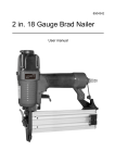
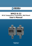
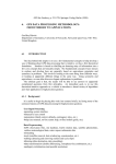
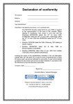
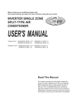
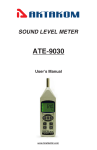
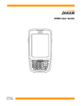
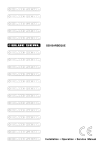
S503 Humidity Calibrator User’s Manual S-503 HUMIDITY GENERATOR RH TEMP 5V 1V mA INPUT SELECT 8 6 3 SETPOINT 15Vdc % RH 10V INPUT VOLT OFF INPUT 4-20mA ON GND 97210 Issue 01, April 2011 Michell Instruments Inside front cover (blank) S503 User’s Manual S-503 HUMIDITY GENERATOR RH TEMP 5V 1V mA INPUT SELECT 8 6 3 SETPOINT 15Vdc % RH 10V OFF INPUT VOLT INPUT 4-20mA ON GND S503-DIG © 2011 Michell Instruments This document is the property of Michell Instruments Ltd. and may not be copied or otherwise reproduced, communicated in any way to third parties, nor stored in any Data Processing System without the express written authorization of Michell Instruments Ltd. 97210 Issue 01, April 2011 iii Michell Instruments S503 User’s Manual Contents Safety............................................................................................................................................... v Electrical Safety.......................................................................................................................... v Toxic Materials........................................................................................................................... v Repair and Maintenance............................................................................................................. v Calibration................................................................................................................................. v Safety Conformity....................................................................................................................... v Abbreviations.....................................................................................................................................vi Recycling Policy.................................................................................................................................vii WEEE and RoHS Compliance.............................................................................................................. vii Calibration Facilities...........................................................................................................................vii Manufacturing Quality....................................................................................................................... viii Warranty......................................................................................................................................... viii Return Policy.................................................................................................................................... viii 1 INTRODUCTION......................................................................................................................... 1 1.2 Applications..................................................................................................................... 1 1.3 Dimensions..................................................................................................................... 1 1.4 S503 Combinations.......................................................................................................... 2 1.4.1 S503-DIG.................................................................................................................... 2 1.4.2 S503-DIG-OPT............................................................................................................. 2 1.4.3 S503-DIG-SET............................................................................................................. 3 1.4.4 S-503-DIG-LC.............................................................................................................. 3 2 OPERATION............................................................................................................................... 4 2.1 Front Panel Functions....................................................................................................... 5 2.2 Back Panel Functions....................................................................................................... 6 2.3 Getting Started................................................................................................................ 7 2.4 Operating Instructions...................................................................................................... 8 2.5 Connecting a Transmitter................................................................................................. 8 3 MAINTENANCE........................................................................................................................... 9 4 TROUBLESHOOTING.................................................................................................................10 5 CALIBRATION...........................................................................................................................11 Figures Figure 1.1 Figure 1.2 Figure 1.3 Figure 1.4 Figure 1.5 S503 dimensions.......................................................................................................1 S503-DIG Digital Humidity Generator.........................................................................2 S503-DIG-OPT Digital Humidity Generator & Optidew Vision.......................................2 S503-DIG-SET Calibration Kit.....................................................................................3 S503-DIG-LC S503 with extended chamber.................................................................3 Figure 2.1 Figure 2.2 Figure 2.3 Figure 2.4 Figure 2.5 Inside the S503.........................................................................................................4 S503 front panel.......................................................................................................5 S503 back panel.......................................................................................................6 Maximum water level................................................................................................7 Sponge inside chamber.............................................................................................7 Appendices Appendix A Technical Specifications............................................................................................13 Appendix B Recommended Practices in Humidity Measurements...................................................15 Appendix C List of Worldwide Michell Instruments’ Offices...........................................................20 97210 Issue 01, April 2011 iv Michell Instruments S503 User’s Manual Safety The manufacturer has designed this equipment to be safe when operated using the procedures detailed in this manual. The user must not use this equipment for any other purpose than that stated. Do not apply values greater than the maximum value stated. This manual contains operating and safety instructions, which must be followed to ensure the safe operation and to maintain the equipment in a safe condition. The safety instructions are either warnings or cautions issued to protect the user and the equipment from injury or damage. Use qualified personnel and good engineering practice for all procedures in this Manual. Electrical Safety The instrument is designed to be completely safe when used with options and accessories supplied by the manufacturer for use with the instrument. Toxic Materials The use of hazardous materials in the construction of this instrument has been minimized. During normal operation it is not possible for the user to come into contact with any hazardous substance which might be employed in the construction of the instrument. Care should, however, be exercised during maintenance and the disposal of certain parts. Repair and Maintenance The instrument must be maintained either by the manufacturer or an accredited service agent. Refer to Appendix B for details of Michell Instruments’ worldwide offices contact information. Calibration Under normal ambient conditions (0 to +50ºC (+32 to +122ºF) 0-70% RH) and for accuracy of ±2% RH, an annual calibration is recommended. For an accuracy ±5% RH a calibration is recommended every five years. For environments with airborne chemicals or for high humidity and high temperature conditions more frequent calibration is recommended. Safety Conformity This product meets the essential protection requirements of the relevant EU directives. Further details of applied standards may be found in Section 5. Michell Instruments v 97210 Issue 01, April 2011 S503 User’s Manual Abbreviations The following abbreviations are used in this manual. AC alternating current DC direct current ºC degrees Celsius ºF degrees Fahrenheit g grams in inches lbs pounds kg kilograms mA milliampere mm millimetres oz ounces % percentage RH relative humidity RS232 serial data transmission standard temp temperature T temperature V Volts Ω Ohms Warnings The following general warning listed below is applicable to this instrument. It is repeated in the text in the appropriate locations. Where this hazard warning symbol appears in the following sections, it is used to indicate areas where potentially hazardous operations need to be carried out. 97210 Issue 01, April 2011 vi Michell Instruments S503 User’s Manual Recycling Policy Michell Instruments is concerned with the protection of the environment. It is our commitment to reduce and eliminate from our operations, wherever possible, the use of substances which may be harmful to the environment. Similarly, we are increasingly using recyclable and/or recycled material in our business and products wherever it is practical to do so. The product that you have purchased may contain recyclable and/or recycled parts and we will be happy to provide you with information on these components if required. WEEE and RoHS Compliance The Waste Electronic and Electrical Equipment (WEEE) Directive, and the Restriction of Hazardous Substances (RoHS) Directive place rules upon European manufacturers of electrical and electronic equipment. The directives’ aim is to reduce the impact that electronic devices have on the environment. Michell products are currently exempt from the RoHS directive, however all future products will be developed entirely using compliant materials. Furthermore, Michell is taking active steps to remove non-compliant materials and components from existing products wherever possible. Michell is in full compliance with the WEEE Directive (Registration No. WEE/JB0235YW). Customers may be required to return certain instruments for treatment at the end of their working life. June 2010 Calibration Facilities Each unit has an internal reference which is calibrated against our working factory standard which is traceable to ‘VSL’ in The Netherlands and National Physical Laboratory (NPL) in the UK. Calibration Certificates: In addition to the normal calibration procedure, each internal reference transmitter can be supplied with its own VSL or NPL traceable calibration certificate. Michell Instruments vii 97210 Issue 01, April 2011 S503 User’s Manual Manufacturing Quality Michell Instruments UK is registered with the British Standards Institute for Quality Assurance to: BS EN ISO 9001: 2008 Rigorous procedures are performed at every stage of production to ensure that the materials of construction, manufacturing, calibration and final test procedures meet the requirements laid down by our BSI approved Quality System. Please contact Michell Instruments if the product does not arrive in perfect working order. Warranty Unless otherwise agreed, the Supplier warrants that, as from the date of delivery for a period of 12 months the goods and all their component parts, where applicable, are free from any defects in design, workmanship, construction or materials. The Supplier warrants that the services undertaken shall be performed using reasonable skill and care, and of a quality conforming to generally accepted industry standards and practices. Except as expressly stated, all warranties, whether express or implied, by operation of law or otherwise, are hereby excluded in relation to the goods and services to be provided by the Supplier. All warranty services are provided on a return to base basis. Any transportation costs for the return of a warranty claim shall reside with the Customer. Return Policy If a Michell Instruments’ product malfunctions within the warranty period, the following procedure must be completed: 1. Notify a Michell Instruments’ distributor, giving full details of the problem, the model variant and the serial number of the product. 2. If the nature of the problem indicates the need for factory service then the instrument should be returned to Michell Instruments, carriage prepaid, preferably in the original packaging, with a full description of the fault and the customer contact information. 3. Upon receipt, Michell Instruments will evaluate the product to determine the cause of the malfunction. Then, one of the following courses of action will be taken: • If the fault is covered under the terms of the warranty, the instrument will be repaired at no cost to the owner and returned. • If Michell Instruments determines that the fault is not covered under the terms of the warranty, or if the warranty has expired, an estimate for the cost of the repairs, at standard rates, will be provided. Upon receipt of the owner’s approval to proceed, the product will be repaired and returned. 97210 Issue 01, April 2011 viii Michell Instruments S503 User’s Manual 1 INTRODUCTION The S503 Humidity Generator/Calibrator enables users of humidity sensors, transmitters and read-out devices to quickly and accurately generate reference humidity conditions at ambient temperatures. 1.1 1.2 Features • Generates humidity levels between 10-90% RH • Highly portable • Fast stabilization of humidity chamber • In combination with Michell Instruments’ Optidew Vision, which works on a proven, fundamental optical dew-point measurement principle, calibrations can be done using the most accurate reference (optional). • Multiple sensors can be calibrated at the same time Applications Calibration and validation of RH transmitters, sensors and data loggers. 1.3 Dimensions Side view Top view A Back view Notes: Hole A = Power Hole for adapter Bottom view Figure 1.1 Michell Instruments 1 S503 dimensions 97210 Issue 01, April 2011 S503 User’s Manual 1.4 S503 Combinations 1.4.1 S503-DIG Figure 1.2 S503-DIG Digital Humidity Generator The S503-DIG consists of - S503, including 7 user-specified port adapters, power adapter, desiccant and adapter tool. 1.4.2 S503-DIG-OPT Figure 1.3 S503-DIG-OPT Digital Humidity Generator & Optidew Vision In combination with Michell Instruments’ Optidew Vision, calibrations can be done using the most accurate reference. The Optidew Vision is traceable to national standards. The Optidew Vision is a high performance Optical Dew-point Transmitter working on a proven, fundamental optical dew-point measurement principle and giving unmatched and drift-free long-term performance. It offers a wide measurement range from -60 to +90°Cdp (-76 to +194°Fdp) (or 0.5 to 100% RH) at temperatures from -40 to +90°C (-40 to +194°F), and -20 to +130°C (-4 to +266°F) at temperatures from -20 to +130°C (-4 to +266°F) for the high temperature version. For more information on the Optidew Vision please contact Michell Instruments or your local distributor (see contact details in Appendix B). The S503-DIG-OPT consists of - S503, with 5 user-specified port adapters, 2 Optidew adapters (A000272 (stainless steel port adapter) and A000273 (polymer housing port adapter ø18.5mm (0.73”) to ø3mm (0.19”)), power adapter, desiccant and adapter tool. 97210 Issue 01, April 2011 2 Michell Instruments S503 User’s Manual 1.4.3 S503-DIG-SET Figure 1.4 S503-DIG-SET Calibration Kit The S503-DIG-SET consists of - S503, including hand meter and probe (with calibration certificate), 7 user-specified port adapters, power adapter, desiccant, distilled water bottle (water not included), adapter tool and carrying case. 1.4.4 S-503-DIG-LC Figure 1.5 S503-DIG-LC S503 with extended chamber The S503-DIG-LC has an extended chamber (0.54 liter extra) Michell Instruments 3 97210 Issue 01, April 2011 S503 User’s Manual 2 OPERATION Desiccant chamber Power supply 12 V DC Water chamber Calibration chamber Figure 2.1 Inside the S503 A vapor saturator and desiccant chamber are coupled to the calibration chamber. Saturated or dry air is pumped into the chamber to achieve the set point. The electronics assure fast ramping to the actual calibration point. An LCD displays the actual chamber humidity, as well as the actual chamber temperature. The S503 utilizes a high accuracy reference sensor which has been calibrated to a traceable reference. The overall accuracy between 20 and 80% RH is ±2% RH. Although the internal reference is accurate and stable, an external reference probe, either a traceable RH indicator or a chilled mirror dew-point probe, is recommended as the calibrated reference. 97210 Issue 01, April 2011 4 Michell Instruments S503 User’s Manual 2.1 Front Panel Functions 1 2 3 4 5 67 8 9 10 S-503 HUMIDITY GENERATOR RH TEMP 1V mA 8 6 3 OFF INPUT VOLT 11 12 13 SETPOINT 15Vdc INPUT SELECT % RH 5V 10V 14 INPUT 4-20mA ON GND Figure 2.2 1. Display Screen Input Select S503 front panel 2. Temp Shows the actual calibration chamber temperature 3. RH Shows the actual calibration chamber relative humidity 4. 10 V Shows the actual output of a transmitter in the calibration chamber with an output of 0-10 V. Display reads from 0-100%RH / 0 to +100ºC 5. 5 V Shows the actual output of a transmitter in the calibration chamber with an output of 0-5 V. Display reads from 0-100%RH / 0 to +100ºC 6. 1V Shows the actual output of a transmitter in the calibration chamber with an output of 0-1 V. Display reads from 0-100%RH / 0 to +100ºC 7. mA Shows the actual output of a transmitter in the calibration chamber with an output of 4-20 mA. Display reads from 0-100%RH / 0 to +100ºC 8. Set point Selects the desired relative humidity: 10-90% RH in steps of 0.1% RH 9. Humidify When lit, indicates that the vapor saturator is activated 10. De-Humidify When lit, indicates that the desiccant chamber is activated 11. 15 V DC +15 V DC supply for a transmitter in the calibration chamber 12. Input Volt Connect to v+ transmitter signal in the calibration chamber with voltage output (0-1, 0-5 or 0-10 V) 13. Input mA Connect to + signal of transmitter in the calibration chamber with current output (2-wire 4-20 mA) 14. Gnd Common ground for v- transmitter signal and power supply Michell Instruments 5 97210 Issue 01, April 2011 S503 User’s Manual 2.2 Back Panel Functions Power Supply Socket Figure 2.3 S503 back panel The power supply cable comes with a country-specific plug attached. The input is 12 V (850 mA). 97210 Issue 01, April 2011 6 Michell Instruments S503 User’s Manual 2.3 Getting Started Stabilize the unit to room temperature before use. Always close the calibration chamber ports before use. • Remove the cover from the desiccant chamber (see Figure 2.1) and fill with 25g of new desiccant. • Remove the cover and the blue sponge (see Figure 2.5) from the water chamber (see Figure 2.1) and fill with water to BELOW the maximum water level. Maximum water level (shown with cover removed) Figure 2.4 Maximum water level Do not overfill as the water can flow directly to the calibration chamber, causing the generator to malfunction. IMPORTANT: THE CALIBRATOR SHOULD NOT BE TRANSPORTED WHEN FILLED WITH WATER. ALL WATER MUST BE DRAINED BEFORE MOVING THE UNIT (SEE SECTION 3 FOR DETAILS) • Place the blue sponge back into the water chamber - this sponge prevents water from entering the grey tube and water droplets getting into the humidity chamber. Figure 2.5 Michell Instruments Sponge inside chamber 7 97210 Issue 01, April 2011 S503 User’s Manual 2.4 Operating Instructions 1. The unit must be used at normal room temperature (approximately +20ºC (+68ºF)) and must be stabilized for a minimum of 1 hour, if used for different temperature environments. 2. Power the unit with 12 V DC (connection at the rear of the instrument). A 100 - 240 V AC adapter is included. 3. Make sure the calibration ports are closed. 4. Switch the unit to ‘RH’ and choose the desired humidity. 5. Install the humidity transmitter to be calibrated (without filter) into the calibration chamber. 6. If applicable, connect the transmitter to the built-in power supply and read out. See Section 2.5 for further information. 7. Press ‘ON’. The unit will now start to dry or humidify, depending on the humidity set, until it reaches its set point. 8. If the humidity probe is connected to the built-in power supply and read out, switch to the corresponding input sensitivity. If the transmitter has an output: • of 0-10 V, switch to ‘10 V’ • of 0-5 V, switch to ‘5 V’ • of 0-1 V, switch to ‘1 V’ • of 4-20mA switch to ‘mA’ The display shows the actual output of the transmitter under calibration. 2.5 Connecting a Transmitter The S503 Humidity Generator/Calibrator accepts any probe with a diameter varying from 5mm to a maximum of 25mm. The S503 has a built-in power supply of 15 V DC for transmitters under calibration. For example, if the transmitter under calibration has a 0-10 V output, the output signal should be connected to the voltage input and the input select switch should be set to 10 V. The actual reading of the transmitter is shown on the display from 0-100% RH. To see the actual relative humidity in the chamber the input select switch should be set to ‘RH’. Before placing the transmitter in the calibration chamber, remove the dust filters. Use slotted caps only - this will reduce the stabilization time of the transmitter under calibration. 97210 Issue 01, April 2011 8 Michell Instruments S503 User’s Manual 3 MAINTENANCE WATER Only add distilled water to the water compartment. Do not shake or turn over the instrument as water may flow into the calibration chamber or internal electronics. Do not overfill as the water can flow directly to the calibration chamber, causing the generator to malfunction. IMPORTANT: THE CALIBRATOR SHOULD NOT BE TRANSPORTED WHEN FILLED WITH WATER. ALL WATER MUST BE DRAINED BEFORE MOVING THE UNIT. To remove water (either when exchanging the water or removing before transportation): • Remove the cover and sponge from the water chamber. • Use a syringe to remove the water from the chamber. • Replace the sponge and the cover. DESICCANT Replace desiccant when colorless. Use only dark blue or orange, ultra dry desiccant. The desiccant can be regenerated by heating it to +150ºC for 1-2 hours. NOTE: Remove water before removing desiccant. To remove desiccant: • Firstly, remove water by following the above instructions. • Remove the cap from the desiccant chamber. • Turn the S503 upside-down to remove the desiccant. • Use only genuine desiccant to refill. Michell Instruments 9 97210 Issue 01, April 2011 S503 User’s Manual 4 TROUBLESHOOTING UNIT DOES NOT DRY • Desiccant may be saturated (transparent color) Replace with fresh ultra dry desiccant following the instructions in Section 3. • Condensation or water may be on the wall of the calibration chamber Remove the ports and open the chamber. Wipe carefully with a dry cloth and allow to dry for approximately 15 minutes. • Calibration chamber may contain standing water Remove the water and allow the unit to dry for 2 days with all the ports open or with the top plate removed. UNIT IS TOO MOIST OR TOO DRY • Chamber temperature could be extremely cold or hot Stabilize to room temperature. • Cover is open or there is leakage through the cover Unscrew and remove the top plate of the instrument and check the seals around the chambers (see Figure 2.1). LARGE DEVIATIONS IN CALIBRATION • Large calibration deviations when starting up are usually a result of a difference in temperature between the transmitter under calibration and the actual chamber temperature. Allow to stabilize for at least 1 hour. 97210 Issue 01, April 2011 10 Michell Instruments S503 User’s Manual 5 CALIBRATION Calibration Interval Time: Under normal ambient conditions (0 to +50ºC (+32 to +122ºF) 0-70% RH) and for an accuracy of ±2% RH, we recommend an annual calibration. For an accuracy of ±5% RH we recommend calibration every five years. For environments with airborne chemicals or for high humidity and high temperature conditions we recommend more frequent calibration. EMC Compatibility: The series S503 Humidity Generators/Calibrators are designed to meet the following European standards: EN 61326 (1997) + A1 (1998) + A2 (2001) Emission: Class B Immunity: Industrial EN 61000-3-2 (1995) + A1 (1998) + A2 (1998) EN 61000-3-3 (1995) Michell Instruments 11 97210 Issue 01, April 2011 S503 User’s Manual Appendix A Technical Specifications 97210 Issue 01, April 2011 12 Michell Instruments S503 User’s Manual Appendix A Technical Specifications Humidity Generation range 10-90% RH in steps of 0.1% RH Accuracy ±2% RH or better (5-95% RH) Stability chamber Better than ±0.5% Stabilization time to set point <10 minutes Temperature Temperature accuracy ±0.3ºC (±0.54ºF) - internal reference Operating temperature (ambient) +15 to +35ºC (+59 to +95ºF) Sensor Under Calibration Voltage read out 0-1, 0-5, 0-10 V Current read out 4-20 mA Voltage supply 15 V DC, ±10% at 30 mA max General Probe ports 7 off sensor body diameters 5 to 25mm (0.2 to 0.98”) accommodated by port adapters Desiccant chamber 25g (0.88oz) capacity Saturation chamber 25ml capacity, distilled water Display 3½ digit LCD, 13mm (0.5”) characters Supply 12 V DC (100 - 240 V AC adapter included) Weight 1.85kg (4.08lb) Michell Instruments 13 97210 Issue 01, April 2011 S503 User’s Manual Appendix B Recommended Practices in Humidity Measurements 97210 Issue 01, April 2011 14 Michell Instruments S503 User’s Manual Appendix B Recommended Practices in Humidity Measurements The following text is reproduced with kind permission from the National Physical Laboratory. It is originally published in the booklet, A Guide to the Measurement of Humidity. Definition of Relative Humidity Relative Humidity – The ratio of the actual vapor pressure to the saturation vapor pressure over a plane liquid water surface at the same temperature, expressed as a percentage. This is commonly understood when the term ‘X percent relative humidity’ is used. For actual vapor pressure, e, and saturation vapor pressure, es e relative humidity (in %) = ––– x 100 es USAGE: The phrase ‘relative humidity’ is commonly abbreviated RH although this is not a recognized abbreviation. Values of relative humidity are commonly expressed in units of percent relative humidity (% RH). Recommended practices in humidity measurements General practical recommendations • Where relative humidity is of interest, a direct measurement of relative humidity is usually best. Where an absolute measure of humidity is needed, choose dew point, vapor pressure or similar measurements. • Establish the measurement requirements at the purchasing stage in order to have the right instrument for the job. • Allow hygrometers to equilibrate in any new environment. This is particularly necessary after changes in temperature due to transportation or storage. Depending on the instrument and on how great the change in conditions, this may require from only a few minutes to many hours. • Follow Michell Instruments’ care instructions for the instrument. Some instruments need routine cleaning or other maintenance. Before using any solvent cleaner, check with Michell Instruments that this will not harm the sensor or other materials of construction. • Wherever possible, ensure that hygrometers are calibrated under the conditions of use, i.e. at similar values of humidity and temperature, and (if relevant) in similar conditions of pressure, airflow, etc. • Keep a record of calibrations and any adjustments to the hygrometer. This will show the long-term stability of the instrument and allow the associated uncertainty to be assessed. • Check instruments, if possible, at intervals between calibrations, by comparison with another (stable) instrument, to monitor for long-term drift. Routine checks are also useful before and after subjecting an instrument to transportation or other stress, which might lead to a shift in its performance. Where the check is against two (or more) instruments this is even better: not only does this add confidence, but in the event of one instrument drifting among a set of three, it can be seen which reading is most suspect. • Cleanliness of the environment will affect different hygrometers in different ways. Dust and airborne droplets should be avoided or filtered out if possible. Contaminants can come from the most surprising sources, ordinary urban pollution, for example. Michell Instruments 15 97210 Issue 01, April 2011 S503 User’s Manual • The readings given by some types of hygrometer are sensitive to gas type. For any Instrument which reads in terms of mass per unit volume, e.g. in grams per cubic metre, it must be confirmed whether the calibration is valid for the gas in use. • Avoid using instruments in direct sunlight or near any other source of heat, unless they are suitably shielded to prevent measurement errors. Sampling in general • Relative humidity measurements should be carried out at a representative temperature. Failure to allow temperature equilibration will lead to a false indication of the relative humidity. • Variations in vapor pressure from place to place can occur where an environment is subject to any addition or removal of water. If so, care must be taken over where to make a measurement in order to obtain a representative result. • Sources and sinks of water vapor should be avoided in any sampling system. Invasion of stray water can be minimised by attention to leaks, hygroscopic materials, droplets and condensation. The lower the humidity, the more critical these precautions are. • Hygroscopic materials should be avoided. Many materials contain moisture as part of their structure, particularly organic materials (whether natural or synthetic), salts (or anything which contains them), and anything which has small pores. Temperature changes can increase the tendency of these materials to affect the humidity of the surrounding air. • Condensation in a sampling process can invalidate humidity measurements by reducing the water content of the gas being measured. What is more, condensed liquid may alter the humidity elsewhere by dripping or running to other locations and evaporating there. In these circumstances, measurement results may be misleading if hygrometer location is not considered carefully. • Water droplets or mist must be avoided. These can result in overestimates of the humidity of the air between the droplets. Such results may exceed 100% RH, or may be impossible to interpret meaningfully. Droplets of liquid also damage some electrical types of humidity sensor. Filtering the air sample can eliminate droplets. • If pumps are used for sampling gas, these should be located after the hygrometer, to avoid contaminating the measurement environment. Where possible, oil free pumps should be used, or filters employed. Oscillations in pressure due to pumping can sometimes be reduced or buffered using a needle valve or a reservoir of large volume. • Special treatments such as filtration can change the amount of moisture in a gas. Some drying agents take out other gases, too • When sealing any sensor or probe into a port or manifold in a duct or chamber, leaks through the probe or electrical cable should be considered. These are not always sealed against passage of ambient air. • Where sampling involves a step change in temperature, pressure or gas flow rate, relative to the process being sampled, results may need to be converted or interpreted. For example ‘pressure dew point’ will differ from the value found after expanding the gas sample to atmospheric pressure. Care should be taken to distinguish between ‘gauge’ and absolute values of pressure. Dew point in general • The measuring environment and all parts of the sampling pathway must be kept above the dew point if condensation is to be avoided. Electrical trace heating or other heating methods should be used if necessary. An excess temperature of 10°C above the dew point is usually a safe margin. • For measurements in the region below 0°C it must be clear whether the condensate is dew or frost. Failure to distinguish between these can result in errors of about 1°C for every 10°C below zero. 97210 Issue 01, April 2011 16 Michell Instruments S503 User’s Manual Relative humidity in general • Due care must be taken of temperature. The effect of temperature on humidity is highly significant. Failure to take this into account can sometimes lead to errors so large that the measurement is meaningless. In many situations, the largest single source of uncertainty in a humidity measurement is the effect of temperature differences from place to place in the process, room or chamber. The importance of considering the temperature effects carefully cannot be overstated when relative humidity is the parameter of interest. • Care must be taken when expressing uncertainties, changes or fractional differences in relative humidity. For example, the difference between 50% RH and 52% RH is 2% RH. This can also be expressed as a difference of 4% of value. It is important to distinguish clearly between these two kinds of statement. Recommendations specific to ranges of measurements • Ambient humidity - Avoid using hygrometers near the body, which is a source of heat and moisture. Do not breathe close to the measurement. • High humidity, above the ambient range - Ample lines should be maintained above the dew point of the gas being measured, to avoid condensation. Electrical trace heating is often the most practical method. • Low humidity, and very dry gases - If possible, prepare for measurements by flushing sample lines and hygrometers with dry gas, or by evacuating to low pressure. Drive off stray residual water by baking assemblies if possible (but not instruments – unless designed for this!). The lower the moisture content to be measured, the more dramatically the required drying time multiplies. • Avoid hygroscopic materials. At low humidity (anything much below a dew point of 0°C) the amounts of water given off by organic and porous materials can dramatically affect the value of humidity. The lower the level of moisture, the more significant the effects. • Choose impermeable materials, to avoid inward diffusion of moisture through sampling tubes and enclosures. Steel and other metals are practically impermeable. PTFE (‘Teflon’) is only slightly permeable and will usually be satisfactory for dew points above -20°C, and sometimes below this level. Materials such as PVC and rubber are relatively permeable and so totally unsuitable at low humidity, and not really satisfactory in any humidity range. • Surface finish of pipework is important for very dry gases. Even the tiny quantities of water adsorbed on the surfaces of non-hygroscopic materials can have significant effect. Polished or electropolished steel is recommended for the best results. • Clean environments are always best for humidity measurements, but this is especially critical at very low humidity. Even fingerprints harbour water. High purity cleaning agents are recommended: Analytical Reagent (AR) quality solvents for oil-based contaminants, and purified water (distilled or de-ionised) for salts. Cleaning should be followed by thorough drying by a clean method. • Sample tubing should be as short in length as possible. The surface area should be minimised by using the narrowest tubing that the flow conditions will permit. • Avoid leaks. Minimising the number of connections (elbows, tees, valves, etc.) helps with this. • Adequate flow of the gas sample should be ensured, to minimise the influence of sources of stray water in the flow path. • ‘Dead ends’ should be avoided, as they cannot easily be flushed. • Back-diffusion of moisture should be minimised, e.g. by fast flow rates of gas, long exhaust tubes after the sensor, or by valves which isolate the low-humidity region from ambient air. Michell Instruments 17 97210 Issue 01, April 2011 S503 User’s Manual Practical recommendations for specific types of hygrometer Relative humidity capacitive sensor • Care should be taken to avoid mechanical shock (impact) or thermal shock (sudden temperature changes). Sensors should be protected from steam or water sprays, and from direct sunlight. • Where a sensor is at risk of exposure to dust, droplets, or the occasional knock during handling, the appropriate guard or filters for the sensor head should be used. • Any temptation to breathe on the sensor, or to wave it over cups of tea, etc. should be resisted. Filters and saturation guarding may protect the sensor, but these actions carry a risk of damage by condensation or other contamination. • Protective filters can slow the response time of sensors. This can be avoided by removing any filter, but the benefit must be weighed against the risk of damage to the sensor. • Sensors should not normally be submerged in liquids. In the case of a resistive (electrolytic) sensor, water or other liquids would certainly damage the sensor beyond repair. • Salt solutions are especially commonly used for calibration of electrical sensors, and should be provided with traceability directly or via a calibrated hygrometer. Protection of sensors from direct contact with salt or solution is most important as contamination would destroy or seriously impair the sensing element. 97210 Issue 01, April 2011 18 Michell Instruments S503 User’s Manual Appendix C List of Worldwide Michell Instruments’ Offices Michell Instruments 19 97210 Issue 01, April 2011 S503 User’s Manual Appendix C List of Worldwide Michell Instruments’ Offices Asia Michell Asia PO Box 3149 Joondalup WA 6027 Australia Tel: +61 893 046587 E-mail: [email protected] Web: www.michell.com/au Benelux Michell Instruments Benelux BV Krombraak 11 4906 CR Oosterhout The Netherlands Tel: +31 162 680 471 Fax: +31 162 437 566 E-mail: [email protected] Web: www.michell.com/nl China Michell Instruments (Shanghai) Ltd Room 505, Qilai Building 889 Yishan Road Shanghai, 200233 P R China Tel: +86 21 5401 2255 Fax: +86 21 5401 2085 E-mail: [email protected] Web: www.michell.com/cn France Michell Instruments SAS 2-4, rue Jean Desparmet 69008 Lyon France Tel: +33 437 53 88 20 Fax: +33 437 53 88 21 E-mail: [email protected] Web: www.michell.com/fr Germany, Austria, Switzerland Michell Instruments GmbH Industriestrasse 27 D-61381 Friedrichsdorf Germany Tel: +49 6172 591700 Fax: +49 6172 591799 E-mail: [email protected] Web: www.michell.com/de Italy Michell Italia Srl Via Capecelatro, 10 20148 Milano Italy Tel: +39 02 4047194 Fax: + 39 02 40010565 E-mail: [email protected] Web: www.michell.com/it Japan Michell Japan KK Musashino Center Building 1-19-18 Nakacho, Musashino Tokyo 180-0006 Japan Tel: +81 422 502600 Fax: +81 422 521700 E-mail: [email protected] Web: www.michell-japan.co.jp Middle East Michell Instruments Middle East P-06, #097 Sharjah Airport Int’l free zone Sharjah, United Arab Emirates Tel: +971 6 5575028 +971 6 5575029 Fax: E-mail: [email protected] North America Michell Instruments Inc 319 Newburyport Turnpike, Suite 207 Rowley, MA 01969 USA Tel: +01 978 484 0005 Fax: +01 978 843 7669 E-mail: [email protected] Web: www.michell.com/us United Kingdom Michell Instruments Ltd 48 Lancaster Way Business Park Ely, CB6 3NW Cambridgeshire England Tel: +44 1353 658000 Fax: +44 1353 658199 E-mail: [email protected] Web: www.michell.com/uk 97210 Issue 01, April 2011 20 Michell Instruments S503 User’s Manual NOTES: Michell Instruments 21 97210 Issue 01, April 2011 S503 User’s Manual NOTES: 97210 Issue 01, April 2011 22 Michell Instruments S503 User’s Manual NOTES: Michell Instruments 23 97210 Issue 01, April 2011 http://www.michell.com