1
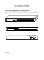
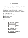
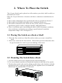
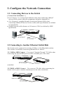
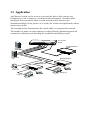
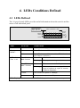
KS-116
16-Port 10/100 Workgroup Switch
Installation Guide
We make no warranties with respect to this documentation and disclaim any implied warranties of
merchantability, quality, or fitness for any particular purpose. The information in this document is subject to
change without notice. We reserve the right to make revisions to this publication without obligation to notify any
person or entity of any such changes.
Trademarks or brand names mentioned herein are trademarks or registered trademarks of their respective
companies.
Installation Guide
16-Port 10/100Mbps Workgroup Switch
Sixteen 10/100Mbps RJ45 TX ports /w one MDI uplink port shared with Port
16.
Front View :
Indicator Panel
MDI-X Ports
MDI Port
Rear View :
Power Switch
Power
P/N:17000067
Power Socket
100-240VAC 1A
Contents
Installation Guide
1. Introduction
1.1 Package Contents
1.2 Installation Procedure
2. Where to Place the Switch
2.1 Placing the Switch onto a Desk or Shelf
2.2 Mounting the Switch onto a Rack
3. Configure The Network Connection
3.1 Connecting Devices to the Switch
3.2 Connecting to Another Ethernet Switch/Hub
3.2.1 MDI to MDX Connect
3.2.2 MDX to MDX Connect
3.3 Application
4. LED Conditions Defined
4.1 LEDs Defined
5. Troubleshooting
5.1 Resolving no Link Conditions
5.2 Q&A
Appendix A - Product Specifications
Appendix B - Cable Specifications
Appendix C - Electro-magnetic and Safety Compliances
Appendix D - Warranty
1. Introduction
This 16-port Switch is a plug-and-play 10/100Mbps Fast Ethernet switching
hub. This switch can auto-sense the operation speed (10Mbps or 100Mbps) and
operation mode (full or half duplex). It is very easy to install and use.
Every network connection can use up to 200Mbps bandwidth to transfer data
because of the switch architecture of the Switch. The total bandwidth of the
Switch is 1.6Gbps. Users can use this 16-port Switch to enhance their network
performance easily. There is a clear indicator panel for Link/Act, Fullduplex/Collision and connection speed of each port for network status monitor.
1.1 Package Contents
l One 16-port 10/100Mbps Ethernet Switch
l One AC power cord
l Two rack-mount kits and screws
l This installation guide
1.2 Installation Procedure
Install the Switch
Section 2
Connecting Devices
to the Switch
Section 3
Diagnosis the
Network Connections
Section 4
Troubleshooting
Section 4, 5
2. Where To Place the Switch
This 16-port Switch can be placed on a flat surface (your desk, shelf or table) or
mounted onto a rack.
Place the 16-port Switch at a location with these connection considerations in
mind:
l
l
l
l
The switch configuration does not break the rules as specified in Section 3.
The switch is accessible and cables can be connected easily to it.
The cables connected to the switch are away from sources of electrical
interference such as radio, computer monitor, and light fixtures.
There is sufficient space surrounding the hub to allow for proper ventilation
(the switch may not function according to specifications beyond the
temperature range of 0 to 40 degrees C).
2.1 Placing The Switch on a Desk or Shelf
1. Place the first switch on a firm flat surface where you want to install the
stack.
2. Place next switch on the first switch. Please don't put more than three this
16-port Switches in a stack to prevent shaking of the stack.
2.2 Mounting The Switch Onto a Rack
1. Use the brackets and screws supplied in the rack mounting kit.
2. Use a cross-head screwdriver to attach the brackets to the side of the switch.
3. Position the switch in the rack by lining up the holes in the brackets with the
appropriate holes on the rack, and then use the supplied screws to mount the
switch onto the standard EIA 19-inch rack.
3. Configure the Network Connection
3.1 Connecting Devices to the Switch
[ Connection Guidelines: ]
Use Category 3 or 5 twisted-pair Ethernet cable when connecting 10BaseT
devices to the switch (cable pin assignments defined in Appendix A)
l Use Category 5 (straight-through) twisted-pair Ethernet cable when
connecting 100BaseTX devices to the switch (cable specifications are defined
in Appendix B)
l Always limit the cable distance to 100 meters (328 ft) as defined by IEEE
specification
l
100BASETX:
Cat-5 Twisted-pair cable
)
Max. 100m (328 feet)
FS
10BASET:
Cat-3,4,5 Twisted-pair cable
)
Max. 100m (328feet)
PC
3.2 Connecting to Another Ethernet Switch/Hub
The Switch can be connected to existing 10 Mbps or 100 Mbps hubs/switches.
The switch to switch/hub connection guidelines are as follows:
3.2.1 MDI to MDX Connect - Use normal "Straight Through" TP Cable when
connecting the Switch MDI port to another standard port at the other
FROM: MDI port
Straight-Through cable
Max. 100m (328feet)
)
TO: MDX port
switch/hub.
3.2.2 MDX to MDX Connect - Use crossover TP cable when connecting the
Switch device port to another standard port at the other switch/hub.
FROM: MDX port
Cross-over cable
Max. 100m (328feet)
)
TO: MDX port
3.3 Application
An Ethernet switch can be used to overcome the hub to hub connectivity
limitations as well as improve overall network performance. Switches make
intelligent decisions about where to send network traffic based on the
destination address of the packet. As a result, the switch can significantly reduce
unnecessary traffic.
The example below demonstrates the switch ability to segment the network.
The number of nodes on each segment is reduced thereby minimizing network
contention (collisions) and boosting the available bandwidth per port.
The 16-port
Switch
FS
Another Ethernet
Switch
FS
Dual Speed Hub
Dual Speed Hub
Power User
Workgroup
Workgroup
4. LEDs Conditions Defined
4.1 LEDs Defined
The 16-port Switch LEDs provide useful information about the switch and the
status of all individual ports.
Green : Link / Act
Yellow : FDX / Col
Yellow : 10M / Green : 100M
Display
Mode
1
2
3
4
5
6
7
8
9
10
11
12 13
14
15
16
Display
Mode
PUSH
Power
LED
STATUS
CONDITION
Power
ON
Switch is receiving power.
Display
Mode**
Green
The LED function of Port 1 ~ 16 is "Link / Act".
Yellow
LEDs of
Port 1~16
if in "Link /
Act" function
The LED function of Port 1 ~ 16 is "FDX / Col."
(Full Duplex / Collision).
ON
Port has established a valid link.
if in "FDX /
Col." function
Flashing
Data packets being received or sent.
ON
The connection is Full Duplex.
Flashing
Green
Packet collisions occurring. A low
level of collision is a part of normal
Ethernet Operation.
The connection speed is 100Mbps.
Yellow
The connection speed is 10Mbps.
** The Display Mode is switched by the "PUSH" (a push button switch) on the panel.
5. Troubleshooting
5.1 Resolving No Link Conditions
The possible causes for a no link LED status are as follow:
l
l
l
l
The attached device is not powered on
The cable may not be the correct type or is faulty
The installed building premise cable is faulty
The switch port may be faulty
Note: Because Port 16 MDI-X port and the MDI port share the same
components, if the Port 16 MDI-X port is used, please don't use the MDI port.
Or, if the MDI port is used, please don't use the Port 16 MDI-X port.
5.2 Q&A
1. Computer A can connect to Computer B, but cannot connect to Computer C
through the 16-port Switch.
ü The network device of Computer C may fail to work. Please check the
link/act status of Computer C on the LED indicator. Try another network
device on this connection.
ü The network configuration of Computer C may be something wrong.
Please verify the network configuration on Computer C.
2. The possible causes for the 16-port Switch no work status are as follow:
ü Power cord or the internal power supply problem. Check the Power LED
indicator.
ü MDI/MDI-X port is misused. Never use MDI port and Port 16 MDI-X port
at the same time because they share the same components.
ü The cable may not be the correct type or is faulty. And the cable length
limit is 100 meters.
ü The installed building premise cable is faulty.
3. The LED display does not work correct.
ü Because the LED of Port 1 ~ 16 can be switched between "Link / Act" or
"FDX / Col." functions, please check if the LED display is in the correct
display mode. Please refer to Section 4 for LED Display.
A. Product Specifications
Access Method
Standards Conformance
Communication Rate
Communication Mode
Media Supported
Indicator Panel
Number of Ports
MDI-X/MDI Selection
Dimensions
Weight
Certification
Emissions
Immunity
Power Consumption
Input Power
Temperature
Humidity
CSMA/CD, 10 Mbps or 100 Mbps
IEEE 802.3 10BASE-T, IEEE 802.3u 100BASETX
10/100 Mbps on RJ-45 ports
Full / Half duplex
10BASE-T - 100 Ohm Category 3,4,5 twistedpair
100BASE-TX - 100 Ohm Category 5 twisted-pair
LEDs for Power, Display Mode, Link/Act(Speed)
or FDX/Col.(Speed). One PUSH button on the
front panel for Display Mode switch.
Sixteen 10BASE-T/100BASE-TX RJ45 ports
Alternate Port
430 x 105 x 44 mm (16.9 x 4.1 x 1.7 inch)
1.4 Kg (3.08lb)
CE Mark
FCC Class A / VCCI Class-I / CISPR Class A
IEC 1000-4-2/3/4
10Watts max.
Full range: 100 to 240V, 50 to 60 Hz
Standard Operating: 0 to 40℃ (32 to 104℉)
Storage: -40 to 70℃ (-40 to 158℉)
5% to 95% (Non-condensing)
Network Bridging Function Filtering, forwarding and learning
Switching Method
Store-and-forward
Address Table
8K entries
Queue Buffer
512K Bytes Shared Buffer
Filtering/Forwarding Rate Line speed
B. Cable Specification
Two different types of cable are specified for use on the 16-port Switch:
l
l
Standard "straight through" cable
Hub to Hub "cross-over" cable
Cable Schematics
1
2
3
4
5
6
7
8
1
2
3
4
5
6
7
8
Standard Straight-Through Cable
Hub / Switch side
Adapter side
Pin #
Pair #
Pin #
Pair #
RX+
White-Green
----------------- 1
RX+
White-Green
RXGreen
----------------- 2
RXGreen
TX+
White-Orange ----------------- 3
TX+
White-Orange
Not Used
Blue
----------------- 4
Not Used
Blue
Not Used
White-Blue
----------------- 5
Not Used
White-Blue
TXOrange
----------------- 6
TXOrange
Not Used
White-Brown
----------------- 7
Not Used
White-Brown
Not Used
Brown
----------------- 8
Not Used
Brown
Hub-to-Hub Cross-Over Cable
Hub / Switch side
Hub / Switch side
Pin #
Pair #
Pin #
Pair #
RX+
White-Green
----- 1
RX+
White-Green
-RXGreen
----- 2
RXGreen
-TX+
White-Orange ----- 3
TX+
White-Orange
-Not Used
Blue
4
Not Used
Blue
Not Used
White-Blue
5
Not Used
White-Blue
TXOrange
----- 6
TXOrange
-Not Used
White-Brown
7
Not Used
White-Brown
Not Used
Brown
8
Not Used
Brown
Cable Type and Use
Connection
Hub to Hub (or Switch)
Hub to Hub (or Switch)
Speed
Cable Type
10Mbps Cross-over, Cat-3,4,5 twisted pair
100Mbps Cross-over, Cat-5 twisted pair
Hub
Hub
Hub
Hub
to
to
to
to
Server or Workstation
Server or Workstation
Print Server
Print Server
10Mbps
100Mbps
10Mbps
100Mbps
Straight-Through,
Straight-Through,
Straight-Through,
Straight-Through,
Cat-3,4,5 twisted pair
Cat-5 twisted pair
Cat-3,4,5 twisted pair
Cat-5 twisted pair
C. Compliances
EMI Certification
FCC Class A Certification (USA)
Warning: This equipment generates, uses, and can radiate radio frequency energy
and, if not installed and used in accordance with the instruction manual, may
cause interference to radio communications. It has been tested and found to
comply with the limits for a Class A digital device pursuant to Subpart B of Part
15 of FCC Rules, which are designed to provide reasonable protection against
such interference when operated in a commercial environment. Operation of
this equipment in a residential area is likely to cause interference, in which case
the user, at his own expense, will be required to take whatever measures are
required to correct the interference.
Canada Department of Communications - Class A
This digital apparatus does not exceed the Class A limits for radio noise
emissions from digital apparatus as set out in the interference-causing equipment
standard entitled "Digital Apparatus", ICES-003 of the Department of
Communications.
VCCI Class-I Compliance (Japan)
CE Mark Declaration of Conformance for EMI and Safety (EEC)
This is to certify that this product complies with ISO/IEC Guide 22 and
EN45014.
It conforms to the following specifications:
EMC: EN55022(1988)/CISPR-22(1985)
EN60555-2(1995)
EN60555-3
IEC1000-4-2(1995)
IEC1000-4-3(1995)
class A
class A
4kV CD, 8kV AD
3V/m
IEC1000-4-4(1995)
1kV - (power line), 0.5kV - (signal
line)
This product complies with the requirements of the Low Voltage Directive
73/23/EEC and the EMC Directive 89/336/EEC.
Warning! Do not plug a phone jack connector in the RJ-45 port. This may
damage this device.
D. Warranty
We warrant to the original owner that the product delivered in this package will
be free from defects in material and workmanship for a period of warranty time
from the date of purchase from us or the authorized reseller. The warranty does
not cover the product if it is damaged in the process of being installed. We
recommend that you have the company from whom you purchased this product
install it.