1
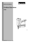
8504342 2 in. 18 Gauge Brad Nailer User manual ※ Technical Data Capacity …………… ………………………………..…….…….100pcs Nail length…………………………………………….……..……15-50mm( 5/8”- 2”) Fastener size……………………………..…………………….….18Gauge (1.25×1.00mm) Operation pressure…………………………………………………70-110PSI(4.8-7.5bar) Air inlet…………………………………………………..………..1/4”N.P.T. Dimension……………………………………………..…………..55×246×249mm Weight………………………………………………..……..……..1.40kg(3.08lb) ※ Important Safety Rules 1. KEEP CHILDREN AWAY. All children should be kept away from the work area. Don’t let them handle the tool. Fig 1. 2. USE SAFETY GLASS AND EAR PROTECTION: Air tool operators and others in work area should always wear safety glass to prevent the injury from fasteners and flying debris when loading and unloading this tool. Maybe the noise would harm your hearing, wear the ear protection to safeguard. (See fig 1.) 3. NEVER USE OXYGEN, COMBUSTIBLE OR ANY OTHER BOTTLE GAS as a power source or would cause explosion and serious personal injury. (See fig 2.) Fig 2. 4. DO NOT CONNECT TOOL TO COMPRESSED AIR which pressure exceeds 120psi. 5. DO NOT PLACE OVER-LONG AIR HOSE in working area in case of the operator’s unexpected tripping .Make sure all connections are tight 6. CARRING TOOL ONLY BY THE HANDLE do not keep the trigger pull on safety Fig 3 yoke mechanism to avoid unintentional firing of fastener. 7. KEEP THE TOOL POINTED AWAY FROM YOURSELF and others at all time and keep hands, any body parts away rear area to Safety guard against possible injury. 8. DISCONNECT TOOL FROM AIR SUPPLY BEFORE LOADING fasteners to prevent a fastener from being fired during connection. (See fig3.) 9. DO NOT KEEP THE TIRGGER OR SAFETY DEPRESSED during loading fasteners or the unintentional firing of a fastener would cause personal injury. 10. DO NOT KEEP THE TIRGGER OR SAFETY DEPRESSED during loading fasteners or the unintentional firing of a fastener would cause personal injury. 11. DISCONNECT TOOL FROM AIR SUPPLY HOSE and close the compressor before performing maintenance, alter the accessories or during non-operation. 12. DO NOT DRIVE FASTENER ON SCAFFOLDINGS,LADDERS and on such similarly construction, not working on airtight case, and vehicles. 13. DO NOT DRIVE FASTENER ON TOP OF NAILED FASTENER, or the fastener can ricochet causing personal injury. 14. NEVER USE A TOOL that is leaking air, had missing or damaged parts or requires repair and make sure all the screws and securely tightened. 15. ONLY USE PARTS AND ACCESSORIES recommend by manufacturer. ※ Operating instruction Description Model F50B drives Ga.18 brad nails from 15mm to 50mm length. Die cast aluminum body for strong and light weight. Comfort grip rubber handle for improved control and comfort even during extended use. Touch-strike security system safe for the operator. Features 360-degree exhaust port can be adjusted to any direction . Quick release nosepiece for fact clearing of jams. It is ideal for door and window trims, decorative trim, and cabinet work, finish paneling, frames, flooring and etc. Air supply 1. Use clean, Dry and Regulated compressed air at 4-7 bar (60-100psi) 2. Never exceed maximum and minimum pressure. Too low or too high pressure would cause noise, fast-worn or misfiring. 3. When connecting air supply always keep hands and body from discharge area of tool. 4. A filter-regulator-lubrication is required and should be located as close to tool as possible.(see fig 4.) 5. Keep air filter clean. A dirty filter will reduce the air pressure to the tool causing a reduction in power and efficiency. 6. For better performance, install a quick connector in your tool and quick coupler on the hose if possible. 7. Be sure all connections in air supply system are sealed to prevent air loss. Fig 4. Tool Loading fastener and operation WARNING: Always disconnect the tool from the compressed air before loading. When loading the tool always point the tool away from yourself and others. Make sure that you are not holding the tool with trigger depressed while loading the tool. 1. Insert a strip of fasteners into magazine Keeping it point down. 2. Release the latch and pusher, slid the pusher against the nails. 3. Connect the tool to the air supply. Make sure the air pressure is in the correct range denoted in the Technical Data. 4. Then test the driving depth in a sample piece of wood before using. If the fasteners are being driven too far or not far enough, adjust the regulator to provide less air pressure or more air pressure. 5. Never operate tool unless safety nose is contact with workpiece. Do not operate tool without fasteners or damage to tool may result. 6. Never fire fasteners into air because fasteners may injury operator or others and damage to tool may result. ※Maintenance WARNING: Disconnect the tool from the air compressor before adjusting, clearing jams, servicing, relocating and during non operation. ·Regular lubrication, if your tool without using the in-liner automatic oilier, place 2 or 6 drops of pneumatic tool oil into the air inlet before each work day or after 2 hours of continuous use depending on the characteristic of workpiece or type of fasteners. ·Check and change all worn or damaged o-rings, seals, etc. Tight all the screws and caps in case personal injury. ·Inspect trigger and safety mechanism to assure safe system is complete and functional: no loose and missing parts, no building or sticking parts. ·Keep magazine and nose of tool clean and free of any dirt lint or abrasive particles. ※ Troubleshooting The following form lists the common operating system with problem and solutions. Please read the form carefully and follow it. WARNING: If any of the following symptoms appears during your operating, stop using the tool immediately, or serious personal injury could result. Only a qualified persons or an authorized service center can perform repairs or replacement of tool. Disconnect tool from air supply before attempting repair or adjustment. When replacing O-rings or Cylinder, lubricate with air tool oil before assembly. SYMPTOM PROBLEM SOLUTIONS Air leak near top of tool or in trigger area 1.O-ring in trigger valve are damage. 2.Trigger valve head are damage. 3.Trigger valve stem ,seal or O-ring are damaged. 1.Check and replace O-ring. 2.Check and replace. 3.Check and replace trigger valve stem, seal or O-ring Air leak near bottom of tool. 1. Loose screws. 2. Worn or damaged O-rings or bumper. 1.Tighten screws. 2.Check and replace O-rings or bumper. Air leak between body and cylinder cap. 1. Loose screws. 2. Worn or damaged O-rings or seals. 1.Tighten screw. 2.Check and replace O-rings or bumper. Blade driving fastener too deep. 1. Worn bumper. 2. Air pressure is too high. 1.Replace bumper. 2.Adjust the air pressure. Tool does not operate well: 1. Inadequate air supply. can not drive fastener or 2. Inadequate lubrication. operate sluggishly. 3. Worn or damaged O-rings or seals. 4.Exhaust port in cylinder head is blocked. 1.Verify adequate air supply. 2.Place 2 or 6 drops of oil into air inlet. 3.Check and replace O-rings or seal. 4.Replace damaged internal parts. Tool skips fasteners. 1.Worn bumper or damaged spring. 2.Dirt in front plate. 3.Dirt or damage prevents fasteners from moving freely in magazine. 4.Worn or dry O-ring on piston or lack of lubrication. 5.Cylinder cover seal leaking. 1.Repalce bumper or pusher spring. 2.Clean drive channel on front plate. 3.Magazine needs to be cleaned. 1.Incorrect or damaged fasteners. 2.Damaged or worn driver guide. 3.Magazine or nose screw loose. 4.Magazine is dirty. 1.Change and use correct fastener. 2.Check and replace the driver. 3.Tighten the magazine. 4.Clean the magazine. Tool jams. 4.O-ring need to be replaced. And lubricate. 5.Replace Sealing washer. ※ Parts Breakdown ※ Parts List No. 1 2 3 4 5 6 7 8 9 10 11 12 13 14 15 16 17 18 19 20 21 22 23 24 Description Bolt Deflector Spring Air Deflector Bolt M5×50 Spring Washer Cylinder Cover O-ring 13.7×2.4 Sealing Washer Compressed Spring Switch Valve Piston Gasket O-ring 31.2×2.5 O-ring 24.8×3.5 Sealing Washer Collar O-ring 26.2×2.4 O-ring 41.7×3 Cylinder O-ring 21×3 Main Piston Bumper Gun body Rubber Washer Rectangle Washer No. 25 26 27 28 29 30 31 32 33 34 35 36 37 38 39 40 41 42 43 44 45 46 47 48 Description Trigger Valve Seat Trigger Valve Stem O-ring 1.7×2 Trigger Valve Guide O-ring 11.2×2 Compressed Spring Step Pin Trigger Safety Spacer E-ring ø 2.5 Safe guide Pusher Spring Safety Stand Spacer Pin 4×20 Ouch Snap Retainer ø2 Pin Cover Plate Pin Bolt M4×14 Driver guide Inlay Slice Fixed Magazine No. 49 50 51 52 53 54 55 56 57 58 59 60 61 62 63 64 65 66 67 68 69 70 71 72 Description Movable Magazine Bolt M4×12 Fixed Seat Stopper Pusher Compressed Spring Bolt M4×7 Washer Fixed Block Pin Lever Bolt M4×8 Spring Support Seat Slice Nut M4 Rubber Handle Case O-ring 36.3×3.55. End Cap Air Inlet Plug Protection cap Spacer O-ring 1.9×1.2