1
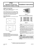
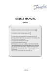
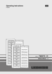
M25_STAN0893_00_SE_C25.QXD
9/4/08
9:54 PM
Page 1
S E C T I O N
F O U R
Refrigerants and the
Refrigeration System
UNIT 25
Accessing Sealed
Refrigeration Systems
OBJECTIVES
After completing this unit you will be able to:
■
■
■
■
■
■
describe the different types of refrigeration service
valves.
explain the operation of gauge manifold valves.
explain how to properly install and remove a gauge
manifold set on manual service valves.
explain the operation of split system installation
valves.
explain how to properly install and remove a gauge
manifold set on Schrader valves.
describe how to gain access to systems without
service valves.
25.1 INTRODUCTION
One of the last things a service technician should do when
troubleshooting a system is attach a set of gauges to the system. Each time a sealed system is accessed there is a chance
that some contaminants can be introduced to the system, or
refrigerant can be lost. However, there are times when a refrigeration system’s operating conditions cannot be accurately
assessed without accessing the system’s refrigerant piping to
determine the pressures. Knowing the temperature difference across the coils, the amperage, and the airflow all give
the technician vital information; but sometimes without the
system operating pressures a final determination of a problem cannot be accurately made.
It is important to attach and remove a gauge manifold
set properly. Understanding how to properly manipulate system access valves and install gauge manifolds is vital to the
personal safety of the service technician. Improper technique
can damage the system or injure the technician. Proper techniques should always be practiced so that they become a
habit performed the same way each time.
SAFETY TIP
The proper personal protective equipment, PPE, for installing refrigeration gauges and manipulating valves
includes safety glasses and gloves. When liquid refrigerant escapes into the atmosphere it boils at extremely cold temperatures. Liquid refrigerant sprayed
in the eyes can cause blindness, sprayed on the skin
can cause frostbite.
1
M25_STAN0893_00_SE_C25.QXD
2
SECTION 4
9/4/08
9:54 PM
Page 2
RESIDENTIAL AND LIGHT COMMERCIAL SYSTEMS
25.2 FACTORY INSTALLED
SERVICE VALVES
With the implementation of the Clean Air Act, all manufacturers are required to install factory-installed service valves
on Type II and Type III equipment. Type I equipment is only
required to have a process stub. Commercial refrigeration
and air conditioning systems have had factory-installed service valves for years.
SERVICE TIP
You must put service valve caps back on all access
ports. This is an EPA refrigerant management requirement. Failure to do so is a violation of EPA rules and regulations. Many service access valve caps have O-rings to
seal the system. Be sure these O-rings are in place before installing the cap to ensure a proper seal. Caps that
have a metal-to-metal seal must be tightened oneeighth turn with a wrench after they have been finger
tightened.
Factory installed service valves may be a manually operated stem shut-off valve, as in Figure 25-1, or a Schrader type
valve. Schrader valves are spring-loaded valves similar to the
valves used on car tires. They have a core that threads down
into them, Figure 25-2. Refrigerant is allowed to flow into
and out of the valve when the core is depressed. To prevent
leaks, Schrader valves should always have their valve caps on
when not in use, Figure 25-3.
Residential split system equipment service valves are
usually located on the suction line and liquid line, Figure 25-4.
The valve on the suction line is used to read the low side system pressure and the valve on the liquid line is used to read
the high side system pressure. Most air conditioning systems
use front-seating split system shut-off valves, as shown in
Figure 25-2 Shrader valve and core
Figure 25-3 Shrader valves should always have their cap on
when not in use
Figure 25-5(b). These valves are used to hold the system refrigerant in during shipping. The gauges connect to the
Schrader valve that is built into them. These valves are normally opened when the unit is installed, and then seldom
used after that. It is not necessary to turn them to read pressure because the Schrader valve in them reads line pressure
regardless of the valve position.
SAFETY TIP
A few residential split systems use manual stem
valves as shown in Figure 25-3(a). The gauge connection on these valves is not a Schrader valve. These
valves must be opened to read pressure. More importantly, they must be closed before removing the
gauges.
Figure 25-1 Manual two-way service valve
M25_STAN0893_00_SE_C25.QXD
9/4/08
9:54 PM
Page 3
UNIT 25
ACCESSING SEALED REFRIGERATION SYSTEMS
3
(a)
(b)
Figure 25-5 Service valves
Figure 25-4 Residential split system installation valves
(b Courtesy Rheem Manufacturing)
On heat pump systems, both lines are on the high side
during the heating cycle. To allow technicians to read low side
pressures in heat, heat pump systems use a third valve which
is always connected to the low side of the system regardless of
the cycle, Figure 25-6. Residential packaged units typically
have a low side and high side Schrader valve mounted on the
outside of the equipment, Figure 25-7.
Commercial refrigeration systems typically have three
manual stem service valves. A suction service valve and a discharge service valve are located on the compressor. A service
valve called the king valve is mounted on the outlet of the receiver. These service valves are equipped with a gauge service
port. Operating refrigerant pressures may be observed on the
service gauge manifold when hoses are connected to these
ports and the valves are cracked open.
ant line, and a service port which is used for servicing the system, Figure 25-8. The refrigerant has two paths it can take
through the valve. It can flow between the middle port to the
line port, the middle port to the service port, or between all
ports. There is not a closed position on these valves because
one of the two exit ports will always be open. Instead, the
terms back seated and front seated are used to describe the
valve positions.
The valve is back seated when the stem is turned all the
way out counterclockwise. This position is called back seated
because the valve is seated on the back port of the valve. In
this position the service port is closed but the middle port is
open to the line port, Figure 25-9. Service valves should always be placed in the back seated position before installing or
removing gauges.
The valve is front seated when the stem is turned all
the way in clockwise. This position is called front seated
because the valve is seated on the front port of the valve.
In this position the line port is closed but the middle port
is open to the service port, Figure 25-10. The front seat
position can be used to isolate refrigeration system components.
25.3 MANUAL STEM SERVICE VALVES
Manual service valves have three ports and two seats. The
three ports include a middle port which connects to the compressor or system, a line port which connects to the refriger-
M25_STAN0893_00_SE_C25.QXD
4
SECTION 4
9/4/08
9:54 PM
Page 4
RESIDENTIAL AND LIGHT COMMERCIAL SYSTEMS
Figure 25-6 The arrow points to the port that is always on the
low side of the system regardless of the operating cycle
Figure 25-7 High side and low side Schrader valves on a
packaged unit
SAFETY TIP
Be sure that internal pressure in the compressor is relieved by recovery and vacuum procedures before attempting to remove an isolated compressor from the
system. Pressure remains in the compressor even after
the service valves are front seated.
Figure 25-8 Two-way system
service valve
SQUARE
HEAD
PACKING
NUT
If the stem is positioned anywhere in between the back
seat and front seat positions, all three ports will be open.
Turning the valve one-half turn off of a fully seated position is called cracking the valve. When checking pressures,
the valves are usually in the back seat cracked position,
Figure 25-11.
The stems on manual service valves should only be
turned with a valve stem wrench, Figure 25-12. The corners
GASKET
SERVICE PORT
VALVE SEAT
REFRIGERANT
LINE
COMPRESSOR
CONNECTION
M25_STAN0893_00_SE_C25.QXD
9/4/08
9:54 PM
Page 5
UNIT 25
ACCESSING SEALED REFRIGERATION SYSTEMS
5
BACK SEAT
REFRIGERANT
STEM ALL THE WAY OUT
Figure 25-12 Square stem service valve and valve wrench
Figure 25-9 Two-way service valve in the back-seated position
FRONT SEAT
REFRIGERANT FLOW
STEM IS ALL THE WAY IN
Figure 25-10 Two-way service valve in the front-seated
position
Figure 25-13 This valve stem has been ruined by a careless
technician using the wrong tool
BACKSEAT CRACKED
of the valve stems round off easily when they are turned
with adjustable wrenches or pliers. Once a stem is rounded
it cannot be turned with the correct wrench, Figure 25-13.
The cap for the valve stem and the cap for the service port
should always be replaced after using manual service
valves.
25.4 SCHRADER VALVES
Figure 25-11 When a two-way service valve is cracked, the
valve is just off of the seat,creating a small opening, or crack
Schrader valves provide a convenient method of checking
system pressures or servicing the system where it is not economical or convenient to use manual stem service valves. The
Schrader valve core, shown in Figure 25-14, is a spring loaded
device for positive seating. The valve is like those used on automobile tires, but the cores used in refrigeration valves are
M25_STAN0893_00_SE_C25.QXD
6
SECTION 4
9/4/08
9:54 PM
Page 6
RESIDENTIAL AND LIGHT COMMERCIAL SYSTEMS
Figure 25-16 This cutaway shows how a Schrader valve
works
Figure 25-14 Schrader valve core
(a)
Figure 25-15 The core depressor on the refrigerant hose
pushes in the Schrader valve core when the hose is connected
not the same as the cores used in car tires. The rubber used in
tire valves is not compatible with refrigerants and would dissolve if used on a refrigeration system.
The stem must be depressed to force the valve seat
open against spring pressure. Refrigerant hoses with built
in core depressors must be used with Schrader valves.
When a hose with a core depressor is connected to a Schrader
valve, the valve core is pushed in and the valve opens,
Figure 25-15. Ideally, the seal in the gauge hose will seat
just as the depressor is pushed in and very little refrigerant
will escape. Flow through a Schrader valve is limited because the core takes up most of the space in the center of
the valve. This leaves only a small passage for refrigerant to
go through, Figure 25-16.
If a valve core leaks, it can be replaced by using a coreremoval tool to unscrew it. Some tools, such as the one in
Figure 25-17, allow this to be done while the system is under
pressure. All Schrader valves should have a leak-proof cap on
them when not in use. The cap can prevent refrigerant loss
even if the valve core does leak.
(a)
(b)
Figure 25-17 This tool can be used to change the core in a
Schrader valve without losing the refrigerant in the system
M25_STAN0893_00_SE_C25.QXD
9/4/08
9:54 PM
Page 7
UNIT 25
Figure 25-18 The condensing unit is shipped with the valve
closed to hold in the system refrigerant
25.5 SPLIT SYSTEM
INSTALLATION VALVES
ACCESSING SEALED REFRIGERATION SYSTEMS
tions, and save time on almost any work that must be done
on the system. The most common gauge manifold test sets
contains two shut-off valves, three external connections, and
two pressure gauges. The gauges and the flexible hoses that
connect to the manifold to connect it to the system are color
coded; blue is the low side of the system, red is the high
side. The left-hand gauge is called a compound or suction
pressure gauge. The right-hand gauge is called the high pressure or discharge pressure gauge. The hoses have 1兾4-inside
diameter and are designed to seal on a 1兾4-inch male flare end.
Typically one end is straight and connects to the manifold
and the other end is angled to allow easier connection to
service valves.
More advanced gauge manifolds are available that have
four hose connections and four shut-off valves, Figure 25-19.
Besides the low side and high side connections, there are two
center connections, each with its own shut-off valve. Typically
one of the middle connections allows the use of a 3兾8-inch hose
for faster evacuation.
Most new residential split systems come equipped with unit
installation valves, as shown previously in Figure 25-4. These
valves are used to hold the refrigerant charge in the outdoor
unit while it is shipped. These valves have three ports: the
port to the unit, the line port, and the Schrader valve service
port. Even though they have three ports, they do not behave
like standard manual service valves. No ports are closed in the
back seat position; the Schrader valve service port is always
open to the line port regardless of the position of the valve.
These valves are used primarily for holding the system
charge during shipping. The systems are shipped with the valve
run all the way down clockwise, Figure 25-18. After connecting
the refrigerant lines and indoor coil, the system is evacuated
through the service port. The valve is turned counterclockwise
to open it and allow the trapped refrigerant to flow throughout the system. Typically the valve is never used again because
it does not control refrigerant flow to the service port.
SAFETY TIP
Be careful when opening split system installation
valves. The only thing that keeps the plug in the valve is
a small lock-ring at the top of the valve. Stop turning
when the valve plug approaches the lock-ring. The valve
does not need to be tightened in the counterclockwise,
or up position. Overtightening the valve can cause the
lock-ring to pop out and the plug will fly out under system pressure, with all the system refrigerant behind it.
25.6 GAUGE MANIFOLD SET
Technicians use the gauge manifold to diagnose trouble in refrigeration systems. Gauges allow the operator to watch both
gauges simultaneously during evacuation or charging opera-
7
Figure 25-19 Four valve manifold gauge set
(Courtesy Imperial)
M25_STAN0893_00_SE_C25.QXD
8
SECTION 4
9/4/08
9:54 PM
Page 8
RESIDENTIAL AND LIGHT COMMERCIAL SYSTEMS
25.7 REFRIGERATION GAUGES
Mechanical gauges require a physical device to translate
pressure changes into movement that can be used to move
a dial. Three types of devices are used in mechanical
gauges: diaphragm, bellows, and Bourdon tube. Diaphragm
gauges are generally used for lower pressures within a limited range and are usually not used in refrigeration. Bellows
gauges are used in refrigeration gauges, but they are not
as common as Bourdon tube gauges. The bellows expand
with an increase in pressure and contract with a decrease
in pressure. Figure 25-21 shows a bellows gauge used in
refrigeration.
Most refrigeration gauges use a Bourdon tube as the operating element. The Bourdon tube is a flattened metal tube
which is sealed at one end, curved and soldered to the gauge
fitting at the other end, Figure 25-22. Figure 25-23 illustrates
how a Bourdon tube operates. The blue shaded section shows
the tube at rest at atmospheric pressure. A rise in pressure inside the tube tends to make the Bourdon tube mechanism
straighten. The position the Bourdon tube will move to when
pressure is applied is shown in Figure 25-23 in the dotted
outline. This movement will pull on the link, which will turn
Figure 25-20 Digital manifold gauge set
(Courtesy of Ritchie Engineering Company, Inc.—Yellow Jacket® Products)
The most advanced gauge manifolds use digital gauges
rather than analog bourdon tube gauges, Figure 25-20. These
provide more accurate pressure measurement, built in saturation temperature charts for several refrigerants, and system
analysis.
All gauge manifold sets are test instruments and should
be handled carefully.
■
■
■
Never drop or abuse the gauge manifold.
Keep ports or charging lines capped when not in use.
Never use any fluid other than clean oil and refrigerant.
SAFETY TIP
There are two major groupings of gauge manifold sets.
One group is designed to be used with R-12, R-22,
R-134A, R-408, R-407, and R-404. The other groups of
gauge manifold sets are designed to be used with R-410A
only. Do not use gauges designed for the lower pressured
refrigerants on the very high pressure R-410A system.
Figure 25-21 Example of a bellows style refrigeration gauge
(Courtesy of REFCO Manufacturing Ltd.)
M25_STAN0893_00_SE_C25.QXD
9/4/08
9:54 PM
Page 9
UNIT 25
ACCESSING SEALED REFRIGERATION SYSTEMS
9
Figure 25-24 High side pressure gauge for most common
refrigerants except R-410a
(Courtesy of Yellow Jacket Division, Ritchie Engineering Company)
Figure 25-22 Bourdon tube
the gear sector counterclockwise. The pointer shaft will move
clockwise to move the needle. On a decrease in pressure, the
Bourdon tube moves clockwise toward its original position
and the pointer moves counterclockwise to indicate a decrease in pressure.
Pressure Gauges
The high pressure gauge has a single continuous scale.
Gauge sets made for refrigerants such as R-134a and R-22
are usually calibrated (marked off) to read 0 to 500 psi.
Figure 25-24 shows a high pressure gauge. The scale is usually marked in 5 lb increments. The black scale is the pressure scale and the colored scales indicate the saturation
temperature of different refrigerants at the indicated pressure. For example, if the gauge pointer indicated 200 psi
pressure for R-22, the saturation temperature of the refrigerant would be approximately 101°F.
Pressure gauges made for R-410a have a higher pressure
range because of the higher pressures of R-410 systems.
R-410a pressure gauges can typically read pressures up to
800 psig. On an R-410a pressure gauge, each mark on the
pressure scale represents 10 psig pressure. Figure 25-25 shows
a high pressure gauge for R410a systems.
Compound Gauges
Figure 25-23 The dashed line shows how the Bourdon tube
responds to a pressure increase
The low side gauge is a compound gauge that measures both
pressure and vacuum, Figure 25-26. Gauge sets made for refrigerants such as R-134a and R-22 are usually calibrated
from 0 to 30 in of mercury vacuum and from 0 to 120 psig
M25_STAN0893_00_SE_C25.QXD
10
SECTION 4
9/4/08
9:54 PM
Page 10
RESIDENTIAL AND LIGHT COMMERCIAL SYSTEMS
The retard range protects the gauges from damage when a
pressure above their normal range of operation is connected
to them. Gauges for R-134a and R-22 typically have a retard
range of up to 350 psig.
Compound gauges made for R-410a have a higher
pressure range because of the higher operating pressures of
R-410a systems. R-410a gauges can typically read pressures
up to 350 psig and have a retard range up to 500 psig. On an
R-410a compound gauge, each mark on the pressure scale
represents 5 psig pressure. Each mark on the vacuum scale
represents 5 in Hg vacuum.
Like the high pressure gauge, the compound gauge also
has scales calibrated to read saturation temperatures of various refrigerants such as R-134a, R-22, and R-410A. With
these scales it is not necessary to refer to pressure-temperature
tables or curves to calculate pressure-temperature relationships. Figure 25-27 shows a compound gauge for an
R-410A system.
Gauge Accuracy
Figure 25-25 High side pressure gauge for R-410a
(Courtesy of Ritchie Engineering Company, Inc.—Yellow Jacket® Products)
Gauges are classified by their percentage accuracy. Class 1
gauges are accurate to ± 1% of the reading throughout their
range. This means that 100 psig can read anywhere between
99 and 101. Class 1 gauges are the most accurate mechanical
pressure. On a typical compound gauge each mark on the
vacuum scale represents 2 in Hg vacuum and each mark on
the pressure scale represents 1 psig pressure.
It is common for the standing pressure on the low side of
a system to exceed the normal range of the compound gauge.
Figure 25-26 Compound gauge for most common refrigerants
except R-410a
Figure 25-27 Compound gauge for R-410a
(Courtesy of Yellow Jacket Division, Ritchie Engineering Company)
(Courtesy of Ritchie Engineering Company, Inc.—Yellow Jacket® Products)
M25_STAN0893_00_SE_C25.QXD
9/4/08
9:54 PM
Page 11
UNIT 25
ACCESSING SEALED REFRIGERATION SYSTEMS
11
Figure 25-28 Comparison of 21兾2 in, 31兾8 in, and 4 in mechanical gauges
(Courtesy of Ritchie Engineering Company, Inc.—Yellow Jacket® Products)
gauges used in refrigeration. Class 1.6 and class 2 gauges are
accurate to 1.6% and 2%, respectively. Class 2-3-2 gauges
are accurate to 2% for the first third of their scale, 3% for
the middle third, and 2% for the final third of their scale.
Class 3-2-3 gauges are the least accurate gauges used in
refrigeration.
Gauge Size
Gauges are available in different sizes. The most common sizes
are 21兾2", 31兾8", and 4" in diameter. Figure 25-28 shows all three
common sizes of gauges. Larger gauges are easier to read than
smaller gauges. Their larger circumference allows for more accurate increments making them more accurate as well. This is
especially important for gauges that are used over a wider range
of pressure, like gauges designed for use with R-410a.
SERVICE TIP
Refrigeration gauges have a small adjustment screw
that allows the gauge to be zeroed. The gauge is adjusted to zero with the hoses open to atmospheric pressure. However, it is possible for a gauge to zero out but
not read other pressures accurately. From time to time
the technician should attach the gauges to a new cylinder of refrigerant at a known temperature and compare
the pressure reading to the temperature-pressure chart
so that the gauge can be checked for accuracy. Gauges
that are zeroed and are still inaccurate should be
replaced.
25.8 GAUGE MANIFOLD VALVES
The valves on a gauge manifold are used to control the flow
of refrigerant from either side of the manifold to the center.
Figure 25-29 shows a cutaway view of a gauge manifold. It is
not necessary to open the valves on the gauge set to read pressure. The parts above and below each valve are interconnected so the gauges will read pressure at all times when
connected to the system. The valves open or close the path
from each side to the middle port. When both valves are
closed (front seated) the center or utility port is isolated,
Figure 25-30(a).
Slightly opening a valve is called cracking the valve.
Cracking open the low side valve connects the low side and
center hoses, Figure 25-30(b). Some refrigerant can now flow
from the center hose to the system. Fully opening the low side
valve opens the low side port to the center port for full flow
or refrigerant or for evacuating the system, Figure 25-30(c).
With the low side valve closed, cracking open the high
side valve will allow some refrigerant to flow from the high
side to the center hose, Figure 25-30(d). Fully opening the
high side valve opens the high side port to the center port to
remove refrigerant from the system or for system evacuation,
Figure 25-30(e).
Opening both the low and high side valves opens both
the low and high side ports to the center port. This valve position is used for system evacuation, Figure 25-30(f).
25.9 REFRIGERATION HOSES
The refrigeration hoses are an important part of a gauge
manifold set. They are what actually connects the gauges to
the system. Charging and vacuum hoses are available in sizes
M25_STAN0893_00_SE_C25.QXD
12
SECTION 4
9/4/08
9:54 PM
Page 12
RESIDENTIAL AND LIGHT COMMERCIAL SYSTEMS
Figure 25-29 Cutaway of a
gauge manifold
LOW SIDE
GAUGE
LOW SIDE
VALVE HANDLE
HOSE CONNECTED
TO LOW SIDE
HIGH SIDE
GAUGE
VALVES
VALVE
SEATS
HIGH SIDE
VALVE HANDLE
HOSE CONNECTED
TO HIGH SIDE
HOSE CONNECTED TO
REFRIGERANT CYLINDER, VACUUM
PUMP OR RECOVERY MACHINE
of 1兾4", 3兾8", 1兾2", and 5兾8" inside diameter. The most common
size is 1兾4". Refrigeration hoses are available in many colors,
Figure 25-31. Many gauge sets use hoses that are color coded
to the gauges: red for the high side, blue for the low side, and
yellow for the center hose. Many four-port gauge manifolds
have a 3兾8" port for vacuum and come equipped with a 3兾8"
hose. Typical charging hoses have a straight end that connects
to the manifold and an angled end that connects to the
Figure 25-30 Gauge manifold
valve positions
(a)
(b)
(c)
(d)
(e)
(f)
M25_STAN0893_00_SE_C25.QXD
9/4/08
9:55 PM
Page 13
UNIT 25
ACCESSING SEALED REFRIGERATION SYSTEMS
COVER FOR
PROTECTION
BRAID FOR
STRENGTH
13
RUBBER FOR
PERMEATION
PROTECTION
NYLON
PERMEATION
AND MOISTURE
BARRIER
Figure 25-31 Refrigeration hoses are available in many colors
UL RECOGNIZED ASSEMBLY
(Courtesy of Ritchie Engineering Company, Inc.—Yellow Jacket® Products)
Figure 25-33 Diagram of refrigeration hose construction
(Courtesy of Ritchie Engineering Company, Inc.—Yellow Jacket® Products)
25.10 CONNECTING A GAUGE
MANIFOLD SET ON MANUAL
SERVICE VALVES
Figure 25-32 The angled end contains a core depressor for
Schrader valves
system. The angled end contains the core depressor for
Schrader valves, Figure 25-32.
Refrigeration hoses are not simply a single tube; they
are built in layers. Figure 25-33 illustrates the construction
of a refrigeration hose. The rubber seen on the outside
simply provides physical protection for the inner layers.
The woven fabric layer just under the outer rubber layer
provides strength. Some refrigeration hoses have two
more inner layers, while others have only a single inner
layer. The innermost layer actually contains the refrigerant. Hoses with two inner layers have extra permeation
protection.
Hoses designed for use with refrigerants which operate at
lower pressures than R-410a typically have a working pressure
of 500 psig and a minimum burst pressure of 2,500 psig. Hoses
designed for use with R-410a typically have a working pressure
of 800 psig and a minimum burst pressure of 4,000 psig.
Locate the suction service valve. It is usually located on the
compressor where the suction line attaches. Check to make
sure the service valve stem is back seated. This will ensure that
no pressure is currently applied to the gauge port of the service valve. Remove the gauge port flare cap and attach the hose
connected to the compound side of your gauges to the gauge
port. Locate the discharge service valve. It is also located on
the compressor, but it is the valve connected to the smaller
discharge line leaving the compressor. Check to be sure the
valve stem is back seated. Remove the gauge port cap and attach the hose connected to the high side of the manifold to
the gauge access port on the discharge service valve.
The gauge manifolds and connecting lines should be
purged to avoid system contamination from air and moisture. To purge a unit that does not operate in a vacuum, crack
both the suction and discharge service valves. Open the gauge
manifold valves one at a time and bleed refrigerant out the
middle line until all the air is out. This usually just takes a few
seconds. This will purge the gauge manifold and the connecting lines. Many technicians simply loosen the hoses at
the manifold connections and purge each hose. However, this
does not purge the manifold or middle line.
SAFETY TIP
Contact with the gases being purged should be avoided.
Oil and liquid refrigerant will sometimes escape during the
purging process. Liquid refrigerant can cause frostbite.
The high side is used to purge both sides of the manifold
on systems whose low side is likely to be in a vacuum. To purge
from the high side only, connect the lines as before, but crack
only the high side service valve. Open the low side and high
side manifold valves at the same time and loosen the hose
M25_STAN0893_00_SE_C25.QXD
14
SECTION 4
9/4/08
9:55 PM
Page 14
RESIDENTIAL AND LIGHT COMMERCIAL SYSTEMS
connection at the low side service valve. This will purge everything but the middle hose. It can then be purged separately by
loosening the middle hose at the plug connection. This procedure will work on any system with manual service valves, but
is only necessary when the low side is likely to be in a vacuum.
Some technicians purge the hoses and gauges from a
separate refrigerant tank. This has the advantage of not losing any of the system charge. It has the disadvantage of requiring a drum of refrigerant even if you are just checking
the pressures. To use this method, connect your gauges as
before; except, connect the middle leg to the refrigerant
drum. Do not open the service valves. Crack the tank valve
and open both manifold valves. Loosen the refrigerant hoses
at both the suction and discharge service valves and purge
each individually. After both hoses are purged, close the
valve on the refrigerant cylinder and close the manifold
valves.
25.11 REMOVING A GAUGE
MANIFOLD SET FROM MANUAL
SERVICE VALVES
The simplest way to remove the gauge set is to back seat both
the service valves. This should prevent any further escape of
refrigerant into the gauges. There is still a considerable
amount of refrigerant in the gauges and hoses that needs to be
carefully released. Generally it is easier to release the refrigerant through the middle leg. Disconnect the middle hose at the
plug connection and direct it into an empty can or other safe
area. Slowly open each manifold valve, one at a time, until all
the refrigerant has been released from the gauges.
There is a way to remove the gauges and avoid losing
quite as much refrigerant. Leave the unit running. Instead of
back seating both service valves, back seat only the discharge
service valve. Crack open both manifold valves. This will allow the high pressure gas in the discharge side of the manifold to pass into the low side of the refrigeration system. The
pressure on the gauges will then be equal to the low side operating pressure. This is the lowest pressure any part of the
system will ever have on it. After the pressures in the gauge
manifold have come down to the operating low side pressure,
back seat the suction service valve. The pressure trapped in
the gauges can now be bled off through the middle hose; except now, the trapped pressure is significantly lower.
25.12 CONNECTING A GAUGE
MANIFOLD SET TO SCHRADER
VALVES
Schrader valves automatically open when a hose with a core depressor is connected to them. The service technician normally
does not have control over when the valve opens and closes.
When hoses are connected the valve opens; when hoses are removed the valve closes. Frequently the valve will open before
the seal is made and release refrigerant. If the Schrader valve is
on the liquid line, the liquid that comes out will be extremely
cold as it flashes off at atmospheric pressure. Occasionally the
hose will seat before the core is depressed, and no pressure will
be read. Some manufacturers’ hoses have adjustable core depressors that can help either of these situations, Figure 25-34.
One way of minimizing the risk to the technician is to install the gauges on the Schrader valves with the system off.
This reduces the pressures available at the high side valve
when the hose is connected and reduces the chance of liquid
refrigerant escaping. Connecting with the system off also
makes purging the gauges easier. The gauges may be purged
by opening the valves one at a time and releasing the air
through the center hose.
Tools are available that give the technician more control
over the valve. With control over when the valves open and
SAFETY TIP
If an error or equipment failure causes an unexpected
release of refrigerant, keep your hands and body out of
the refrigerant spray. Do not try to replace a hose or
valve cap on a valve that has refrigerant escaping. Liquid R-410a is approximately –70°F at atmospheric pressure. It does not take long to get a nasty frostbite burn
at that temperature.
Figure 25-34 Adjustable core depressor
(Courtesy of Ritchie Engineering Company, Inc.—Yellow Jacket® Products)
M25_STAN0893_00_SE_C25.QXD
9/4/08
9:55 PM
Page 15
UNIT 25
ACCESSING SEALED REFRIGERATION SYSTEMS
15
Figure 25-35 Thumbscrew core depressor valve
(Courtesy of Ritchie Engineering Company, Inc.—Yellow Jacket® Products)
Figure 25-36 Positive shut-off adapters make connecting to
Schrader valves easier
close, gauges may be safely connected to Schrader valves with
the unit in operation. A valve core removal tool like the one
shown in Figure 25-17 allows gauges to be connected before
opening the valve. Then the tool is used to remove the core,
opening the system to the gauges. This also has the advantage
of improving flow through the valve. This type of core removal tool can be used to change a Schrader valve core without recovering the system refrigerant.
A simpler tool, the thumbscrew core depressor, also allows the connection of gauges before the valve is opened,
Figure 25-35. Turning in the thumbscrew depresses the valve
core and opens the valve. This process is reversed to remove
the gauges. The thumbscrew is turned out, allowing the valve
to close. After the valve is closed, the gauges are removed.
25.13 REMOVING A GAUGE
MANIFOLD SET FROM
SCHRADER VALVES
When a hose is disconnected from a Schrader valve, the refrigerant that is trapped in the hose and gauges comes back
out. This can be a surprising amount of refrigerant when the
high side is connected to the liquid line. Positive shut-off
hoses can drastically reduce the amount of refrigerant released when the gauges are disconnected. Positive shut-off
devices include check valves on the end of refrigerant hoses,
manually operated ball valves on the ends of hoses, and
adapters that can be used with standard hoses. Available
adapters include check valves, mechanisms like the quick
couplings used on air hoses, and ball valves, Figure 25-36.
The check valves built into the end of a hose keep refrigerant from flowing backward out of the hose, Figure 25-37.
Refrigerant will be trapped in the hoses after the gauges have
been disconnected using a positive shut-off valve. Most of the
trapped refrigerant can be put back in the system if the
proper removal procedure is followed.
Using a positive shut-off hose, disconnect the high side
with the unit still operating. Now crack both the gauge mani-
Figure 25-37 The hoses at the top of the picture have a standard
Schrader core depressors. The hoses on the bottom of the
picture have automatic check valves built in that keep the
refrigerant in the hose from coming back out when the hose is
removed.
fold valves to allow the trapped high pressure refrigerant into
the low side. Last, disconnect the low side with the unit still operating. The remaining amount of refrigerant in the hoses can
be safely and legally vented. Note that the gauges must be
purged when they are connected, or part of what is going back
into the system will be air and contaminants.
Three simple steps will reduce your exposure to refrigerant spray if positive shut-off hoses or adapters are not used.
First, wear gloves and safety glasses. It is always a good idea to
wear gloves and safety glasses when handling refrigerant, but
it is especially important when using Schrader valves.
Disconnect the low side with the system operating because
the low side pressure is lower with the unit on. Turn the system off and let the system sit for several minutes before disconnecting the high side, because the high side pressure is
lower with the unit off.
M25_STAN0893_00_SE_C25.QXD
16
SECTION 4
9/4/08
9:55 PM
Page 16
RESIDENTIAL AND LIGHT COMMERCIAL SYSTEMS
Figure 25-39 This gauge is reading 365 psig with a saturation
temperature of 110°F for R-410a
Figure 25-38 This gauge is reading 150 psig with a saturation
temperature of 45°F for R-410a
25.14 READING REFRIGERANT
SATURATION TEMPERATURES
Small systems sometimes only hold a few ounces and putting
gauges on them can remove enough refrigerant to make the
system undercharged. It is definitely not a good idea to install
piercing valves on small sealed systems just to perform a routine check. However, when the refrigeration system must be
accessed a piercing valve or piercing pliers are required.
Refrigeration gauges not only read system pressure, they also
show the refrigerant saturation temperature of common refrigerants. The saturation temperature of a refrigerant may be determined by observing the colored scale for that particular
refrigerant. The gauge in Figure 25-38 is showing 150 psig for an
R-410A system. The needle also points toward its corresponding
saturation temperature, 45°F. The high pressure gauge shown in
Figure 25-39 indicates a pressure of 365 psig and a corresponding temperature for R-410A of 110°F.
25.15 ACCESSING SEALED SYSTEMS
Most small appliances like refrigerators or window units do not
have any valves installed at the factory. Instead, the systems are
evacuated and charged at the factory through process tubes. A
process tube, or process stub, is a copper tube connected to the
system for the sole purpose of evacuating and charging the unit
at the factory. The process tubes can be on the compressor or on
one of the system lines, Figure 25-40. After the system is evacuated and charged at the factory, the process tube is pinched off
and brazed shut.
The only way to gain access to these refrigeration systems is to use a valve that pierces a hole in the tubing. It is better to avoid entering a sealed system unless it is absolutely
necessary because poking a hole in a sealed system can create
problems. The technician could literally be installing a leak.
Figure 25-40 Process tube on hermetic compressor
M25_STAN0893_00_SE_C25.QXD
9/4/08
9:55 PM
Page 17
UNIT 25
ACCESSING SEALED REFRIGERATION SYSTEMS
17
SAFETY TIP
You must wear eye protection and gloves any time you access a refrigeration system. Liquid refrigerant accidentally
released from a pressurized system can be at an extremely
low temperature which can cause blindness and skin
burns. Never position your face or head in a direct line with
an access port as you are attaching or removing hoses.
25.16 PIERCING VALVES
One of the easiest devices available for sealed system access is
the saddle piercing valve, or tap-a-line. These piercing valves
are clamped to the tubing, sealed by a bushing gasket, and then
they pierce the tube with a tapered needle. Most contain some
sort of shut-off control. The technician should keep in mind
that these valves should be used to gain temporary access to a
hermetically sealed system for checking system operating pressures or for pressurizing for leak testing. The piercing valve
shown in Figure 25-41 allows quick access to system pressures
to immediately start diagnosing the refrigeration problem.
SAFETY TIP
Figure 25-42 The needle pierces the copper tubing to gain
access to the refrigeration system
is to install the piercing valve on a process tube. After the refrigerant is recovered, the process tube can be cut and a permanent
valve brazed onto the process tube. Figure 25-43 shows
Schrader valves made for field application.
Before brazing a Schrader valve onto a existing refrigerant
line, all of the refrigerant in the system must be recovered.
Any refrigerant that is allowed to enter the torch flame will
produce a noxious gas. Breathing this gas can be dangerous,
and could even cause lung damage. Remove the Schrader
core before brazing to keep it from becoming damaged.
Bolt on piercing valves are bolted on the line, then the piercing needle is run down to pierce the copper tubing, Figure 25-42.
Refrigerant flows through the hole pierced by the needle to the
service port on the valve.
Bolt on piercing valves should be removed once the source
of the sealed system malfunction has been located. The only
way to do this is to recover the refrigerant from the system
through the piecing valve. After the refrigerant has been recovered, a permanent valve may be brazed on. One way to do this
(a)
(b)
Figure 25-43 (a) Pigtail-type Schrader valve; (b) Schrader valve
Figure 25-41 Bolt on piercing valve
replacement cores
M25_STAN0893_00_SE_C25.QXD
18
SECTION 4
9/4/08
9:55 PM
Page 18
RESIDENTIAL AND LIGHT COMMERCIAL SYSTEMS
Figure 25-44 Steps in installing a braze-on piercing valve. Braze-on piercing valves can be used as both a means of gaining access
to a sealed system as well as a permanent valve.
Braze-on piercing valves are available, such as the one in
Figure 25-44. They function like a Schrader valve after the
tubing is pierced. Braze-on piercing valves can be used for
initial access and left on the system. One safety concern with
braze-on piercing valves is that they are brazed on while the
system is still under pressure. Brazing on a system with pressure still in it is generally considered unsafe. If the tubing is
overheated, it can rupture, allowing refrigerant and oil under
pressure to blast out unexpectedly. The oil spray can ignite
and create a flame thrower effect.
Another tool for accessing sealed systems is a set of piercing pliers, Figure 25-45. These can pierce the tubing and allow
temporary access for system diagnosis and refrigerant recovery.
Since the pliers obviously must be removed, they can only be
used if the technician plans to recover the system refrigerant.
After piercing the system and recovering the refrigerant,
a Schrader valve can be installed. Schrader valves are available for field installation in a variety of forms as seen in
Figure 25-43. The core should be removed from the valve before brazing to avoid melting the plastic seals.
Figure 25-45 These piercing pliers can be used to gain access to sealed systems
M25_STAN0893_00_SE_C25.QXD
9/4/08
9:55 PM
Page 19
UNIT 25
UNIT 25—SUMMARY
Service valves are used to gain access to the refrigeration system. Type II and Type III systems all have
service valves installed at the factory, Type I systems
have process tubes. Commercial refrigeration systems typically use manual stem service valves on the
suction and discharge sides of the compressor and on
the liquid receiver. The normal operating position of
a manual stem service valve is back seated. In the
back seated position the service port is closed.
System pressures can be read in the back seat
cracked position. In the back seat cracked position,
the valve is turned one-half turn off of the back
seated position. Schrader valves are similar to the
valves on car tires. They are found on most residential air conditioning systems. Schrader valves automatically open when a hose with a core depressor is
connected and close when the close is removed.
Type I systems must be accessed using piercing
valves. Bolt-on piercing valves should be used for
system diagnosis and refrigerant recovery, but
should not be left on the system. Braze-on piercing
valves can be used for access and may be left on the
system. Care should be taken when installing a
braze-on piercing valve because of the inherent danger of brazing on a system under pressure.
Gauge manifolds are used to read system pressure. They consist of a compound gauge to read low
side pressures, a high pressure gauge to read high
side pressure, a manifold and valves to control refrigerant flow through the gauges, and hoses to
connect to the system. Gauges are available in a
high pressure range suitable for R-410a, and in a
lower pressure range suitable for everything else.
Positive shut-off hoses or adapters help technicians
control the flow of refrigerant in and out of the
gauges, especially when using Schrader valves. The
saturation temperature of common refrigerants
can be read on the gauges by looking at the colored
scales.
WORK ORDERS
Service Ticket 2501
Customer Complaint: Air Conditioner Freezes Up
Equipment: Packaged Terminal Air Conditioner (PTAC)
Using R-22 Refrigerant
A service technician for the Rest Easy Motel chain is asked
to look at a PTAC in one of the rooms because it cools
poorly and freezes over. Like most PTACs, this one has no
service valves of any kind. The technician knows that the
two most common causes of air conditioning evapora-
ACCESSING SEALED REFRIGERATION SYSTEMS
19
tors freezing over are poor airflow and refrigerant undercharge. The technician decides to check the airflow first.
The air filter is missing and the evaporator is very dirty.
This is most likely causing reduced airflow over the evaporator. After cleaning the coil, the unit airflow is noticeably improved and the evaporator no longer freezes. The
technician elects not to install a piercing valve and keep
the system sealed. Instead, the system operation is
checked by checking the system amp draw, airflow, and
temperature drop across the evaporator coil.
Service Ticket 2502
Customer Complaint: Unit Operates But Does Not Cool
Equipment: Packaged Terminal Air Conditioner (PTAC)
Using R-22 Refrigerant
A service technician for the Rest Easy Motel chain is asked
to look a PTAC in one of the rooms because it operates but
does not cool. Like most PTACs, this one has no service
valves of any kind. The system operation is checked by
checking the system amp draw, airflow, and temperature
drop across the evaporator coil. The amp draw of the
compressor is less than half of the normal RLA rating. The
coil appears clean, the airflow is normal, but the supply air
is the same temperature as the return air; no cooling is
taking place. The technician decides to install a bolt-on
piercing valve on the low side process tube. The reading
on the low side with the compressor operating is 150 psig.
The technician believes the compressor is bad, but decides to install a piercing valve on the high side process
tube to be certain. The pressure on the high side with the
compressor operating is also 150 psig. The compressor is
condemned, the system refrigerant is recovered, the bolt
on piercing valves are removed, Schrader valves are
brazed in, a new compressor and liquid line filter are installed, the system is evacuated to 500 microns, and a
charge is weighed in.
Service Ticket 2503
Customer Complaint: Unit Does Not Cool Adequately
Equipment: Commercial Refrigeration Unit on Walk
in Cooler with R-134a
A technician is called to look at a walk in cooler whose
capacity has noticeably declined. A check of the system
pressures at the suction and discharge service valves reveals that the suction pressure is very low and the high
side pressure is just slightly low. Both the system superheat and subcooling are high. The technician looks for
system restrictions and finds a sweating liquid line filter
drier. The technician determines that the filter drier is restricted and decides to change the filter drier, but does
not want to recover all of the refrigerant. Instead, the king
valve is front seated and the system is operated until the
M25_STAN0893_00_SE_C25.QXD
20
SECTION 4
9/4/08
9:55 PM
Page 20
RESIDENTIAL AND LIGHT COMMERCIAL SYSTEMS
6. How does a Bourdon tube work in a gauge?
filter drier no longer sweats and the pressure on the line
leaving the king valve is 0 psig. The technician turns off
the unit and waits to make sure the pressure does not go
above 0 psig. The old filter drier is replaced with a new filter drier, the system is evacuated from the suction service and king valves to 500 microns, the king valve is back
seated, and the system is returned to service.
Service Ticket 2504
7. What must always be put on a Schrader valve port when not in
use?
8. Why is it not always a good idea to install a gauge set and check
system pressure?
9. What type of units are required to have service valves?
10. What type of units are only required to have process stubs?
11. Explain the difference between the back seated position and the
front seated position on manual stem service valves.
Job: Check Oil for Acidity on Semi-Hermetic Compressor
12. When using manual stem service valves, describe how to position both the service valves and the gauge manifold valves
when reading system pressures.
Equipment: Commercial Refrigeration System with
Semi-Hermetic Compressor
13. Why are positive shut-off hoses helpful when using Schrader
valves?
A-1 Refrigeration changed the compressor is a commercial refrigeration system last week. A technician is sent to
collect a small oil sample and perform an oil acid test on
the oil to see if the oil is contaminated. The technician
does not want to recover all the system refrigerant, but
knows that the refrigerant pressure must be taken off of
the compressor before opening the oil plug, so the technician decides to isolate the compressor using the suction
and discharge service valves. First the system is operated
long enough to warm up the crankcase and boil out any
residual refrigerant from the oil. The system is turned off
and locked out. Then gauges are installed on the compressor and both the service valves are front seated. The
compressor is now isolated from the rest of the system. A
recovery system is used to recover the small amount of
refrigerant in the compressor. The crankcase plug is removed, a small oil sample taken, the plug replaced, and
the oil is tested. The oil is clean, so the technician pulls a
500 micron vacuum on the compressor through the suction and discharge service valves. The service valves are
back seated and the system is put back in operation.
14. What is the purpose of the saddle or piercing valve?
UNIT 25—REVIEW QUESTIONS
1. What do technicians use the gauge manifold for?
2. What are the colors used on a gauge manifold set and what do
they indicate?
15. How can refrigeration gauges show the saturation temperature
of the refrigerant in the system?
16. What is the retard range on compound gauges for?
17. What is the normal pressure range for the compound and high
pressure gauges made for use on R-410a systems?
18. What is the normal pressure range for the compound and high
pressure gauges made for use on R-134a and R-22 systems?
19. What personal protective equipment (PPE) should be worn
when using gauge manifolds?
20. What can be done to reduce the risk of exposure to liquid refrigerant spray?
21. What is the difference between the two ends of a refrigeration
hose?
22. What service valves are normally found on a commercial refrigeration system?
23. Why do split system heat pumps have three service valves?
24. Describe how to remove a gauge manifold set from a system
and put most of the trapped refrigerant back into the system.
25. Describe how to purge a gauge manifold set using only the high
side service valve.
26. Describe how to purge a gauge manifold set when connecting
to Schrader valves.
27. What tool is used to turn the stems on manual stem service
valves?
28. Describe how split system installation valves are used.
3. What is the term for slightly opening a valve?
29. Why are bolt-on piercing valves not supposed to remain on
systems permanently?
4. List three cautions when handling a gauge manifold set.
30. What is a process tube?
5. Why is the low side gauge called a compound gauge?