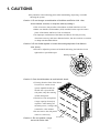
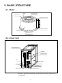
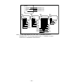
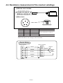
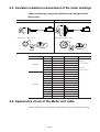
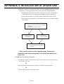
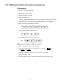
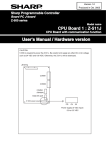
1
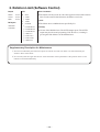
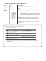
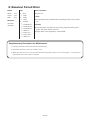
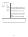
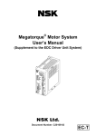
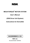
MEGATORQUE® MOTOR
MAINTENANCE MANUAL
(EM/EP Driver Unit)
Document Number: C20026-03
Limited Warranty
NSK Ltd. warrants its products to be free from defects in material and/or workmanship which NSK
Ltd. is notified of in writing within one (1) year of shipment. NSK Ltd., at its option, and with
transportation charges prepaid by the claimant, will repair or replace any product which has been
proved to the satisfaction of NSK Ltd. to have a defect in material and/or workmanship.
This warranty is the sole and exclusive remedy available, and under no circumstances shall NSK
Ltd. be liable for any consequential damages, loss of profits and/or personal injury as a result of
claim arising under this limited warranty. NSK Ltd. makes no other warranty express or implied,
and disclaims any warranties for fitness for a particular purpose or merchantability.
Copyright 1995-2001 by NSK Ltd., Tokyo, Japan
All rights reserved.
No part of this publication may be reproduced in any
form or by any means without permission in writing
from NSK Ltd.
NSK Ltd. reserves the right to make changes to any
products herein to improve reliability, function or
design without prior notice and without any obligation.
NSK Ltd. does not assume any liability arising out
of the application or use of any product described
herein; neither does it convey any licence under its
present patent nor the rights of others.
Patents issued and patents pending.
Contents
1. CAUTIONS ----------------------------------------------------------------------------- 1
2. BASIC STRUCTURE ---------------------------------------------------------------- 2
2.1. Motor ---------------------------------------------------------------------------------------------------------------- 2
2.2. Driver Unit --------------------------------------------------------------------------------------------------------- 2
3. MAINTENANCE AND INSPECTION ------------------------------------------- 3
3.1. Periodic Inspection ----------------------------------------------------------------------------------------------- 3
3.1.1. Motor --------------------------------------------------------------------------------------------------------- 3
3.1.2. Driver Unit (cable included) ----------------------------------------------------------------------------- 3
3.2. Periodic Replacement -------------------------------------------------------------------------------------------- 4
3.2.1. Motor --------------------------------------------------------------------------------------------------------- 4
3.2.2. Driver Unit -------------------------------------------------------------------------------------------------- 4
3.3. Storage -------------------------------------------------------------------------------------------------------------- 4
4. TROUBLESHOOTING -------------------------------------------------------------- 5
4.1. Confirming alarms ------------------------------------------------------------------------------------------------ 5
4.2. Confirming various situations ----------------------------------------------------------------------------------- 5
4.3. Troubleshooting --------------------------------------------------------------------------------------------------- 6
APPENDIX 1: CHECKING THE I/O SIGNALS ---------------------------------- 1
APPENDIX 2: VIEWING THE ALARM STATE ---------------------------------- 4
Appendix 3: DESCRIPTION ALARMS -------------------------------------------- 6
1. Excess Position Error (Slight) ------------------------------------------------------------------------------------- 7
2. Rotation Limit (Software Control) ------------------------------------------------------------------------------- 8
3. Battery Life ----------------------------------------------------------------------------------------------------------- 9
4. Excess Position Error (Serious) --------------------------------------------------------------------------------- 11
5. Internal Switch Setting Error ------------------------------------------------------------------------------------ 12
6. Control Circuit Error ---------------------------------------------------------------------------------------------- 12
7. Memory Error ------------------------------------------------------------------------------------------------------ 13
8. Resolver Circuit Error -------------------------------------------------------------------------------------------- 14
9. Over-Current ------------------------------------------------------------------------------------------------------- 15
10. Heat Sink Over-Temperature ---------------------------------------------------------------------------------- 16
11. Regeneration Resistor Over-Temperature ------------------------------------------------------------------- 17
12. Over-Voltage ----------------------------------------------------------------------------------------------------- 18
13. Control AC Line Under-Voltage ------------------------------------------------------------------------------ 19
14. Main AC Line Under-Voltage --------------------------------------------------------------------------------- 20
15. Internal Fuse Blown --------------------------------------------------------------------------------------------- 21
16. TB Connection Error -------------------------------------------------------------------------------------------- 21
17. Overload ----------------------------------------------------------------------------------------------------------- 22
APPENDIX 4: ASSESSMENT OF MOTOR USEABILITY --------------- 23
APPENDIX 5: INITIALIZATION OF DRIVE UNIT ----------------------------- 26
APPENDIX 6: HOW TO EXCHANGE EM DRIVER UNIT ------------------- 29
-i-
Blank Page
- ii -
1. CAUTIONS
¡Pay attention to the following points when maintaining, inspecting, or trouble
shooting the system.
Caution 1: Do not change a combination of the Motor and Driver Unit. Also,
do not extend, contract, or relay the cable by cutting it.
™This is because, data peculiar to that Motor are held in the Driver Unit.
™Make sure that the serial numbers (S/N) inscribed on the respective name
plates of the Motor and Driver Unit are identical.
™An improper combination of the Motor and Driver Unit may not only
deteriorate accuracy and cause abnormal noises, but also result in no rotation
or abrupt uncontrollable Motor.
Caution 2 :Do not further tighten or loosen the bearing tap bolts of the Motor’s
rotor (inner).
™In order to adjust the pressure of the built-in bearing, the bolts have been
tightened at a specified torque.
Bearing Tap Bolts
Caution 3: Care should be taken to avoid electric shock.
™Viewing from the front of the Driver
Unit, there is a main circuit
(power amplifier board) on
the left side. Open the left
side panel, only after turning
off the main power.
PE
TY
.
NO
™The Driver Unit incorporates
TB
a large-capacity electrolytic
capacitor. After turning off
T
FG
A+
DEF0
1
SW
S
RE
34
12
BC
C+
Y
RD
M1
AL
M2
AL 3
M
AL
9A
B–
5678
™Do not remove the side panels
unless it is necessary.
C–
ITY
V
F1
–1–
3
CNOLVER
A–
B+
Caution 4 : Do not conduct a mega
test on the Driver Unit.
2
S
ER
OW
IN P
MA
JAPN
CN
~
ER
OW
T.P 0V ~
CON ~ 24
0
R
AC9
the main power, a voltage still
remains for a few minutes.
E IN
MAD
1
VR
250
20A
N1
C
Left side panel
0A
V2
F2
C
LO
VE
D
GN
)
(NC
250
R 1
WE AT
POR HEAT2
OVR HEAT3
OVR HET
OVR CV LT
UDR VORR
OVR CU T
OVR MV
UD
2C
-23
RS
2. BASIC STRUCTURE
2.1. Motor
Rotor
Through Hole
Dust Cover
Resolver Connector
Motor Connector
Housing
Mounting Base
2.2. Driver Unit
*Terminal Block TB
TB
TYPE
CB Board
NO.
VR1
MADE IN JAPN
~
CONT.POWER
AC90 ~ 240V
Connector CN2
~
R
CN2
S
MAIN POWER
T
FG
A+
A–
B+
LED
B–
RDY
ALM1
C–
ALM2
ALM3
RDC Board
CN3
01234
RESOLVER
9ABC
F
US
S
FU E
SE
E
Fuse
SW1
5678
F1 250V 20A
(NC)
FU
DEF
C+
F2 250V 20A
FU
SE
F
US
S
FU E
Connector CN3
POWER
OVR HEAT1
OVR HEAT2
OVR HEAT3
UDR CVT
OVR VOLT
OVR CURR
UDR MVT
CN1
VELOCITY
GND
RS-232C
E
LED
Check Pins
[Shows Velocity]
Connector CN1
¡The above figure shows the EM type. For the EP type, those parts marked with “*”
are duplicated.
–2–
3. MAINTENANCE AND INSPECTION
3.1. Periodic Inspection
3.1.1. Motor
¡Since the Megatorque Motor does not have wear parts in both the Motor and
resolver, simple daily inspection is enough. The following table shows the
inspection items. Inspection frequencies are just yardsticks.
¡Set appropriate ones depending on the working environment and conditions. In
maintenance and inspection, never disassemble the Motor and resolver. When it is
necessary to disassemble the motor, contact us.
Item
Frequency
Vibration and
noise check
Daily
Method
Touch and hearing
Appearance
According to degree
check
of stain/damage
Insulation
Remarks
There should be no change when
compared with normal condition.
Clean with cloth, air, etc.
Disconnect from the Driver Unit
resistance
Annually
and measure between the coil and O.K. if 10MΩ or more
measurement
Overall check
earth at 500 V mega.
According to
necessity
Disassembly and check
3.1.2. Driver Unit (cable included)
¡The Driver Unit uses high-reliability semiconductors and is made contactless. Daily
maintenance is not necessary. However, check the following items at least once a
year.
Item
Frequency
Method
Further tightening
At least annually
Cleaning
At least annually
Electric parts check
At least annually
Cable check
At least annually
Remarks
Terminal board’s terminal block,
connector setscrews, etc.
Eliminate dust, foreign
substances, etc. from the inside.
Check discoloration, breakage,
etc. visually.
Check scratch, crack, etc.
When moving, make an
visually.
appropriate check particularly.
–3–
3.2. Periodic Replacement
3.2.1. Motor
¡The Motor has not periodic replacement parts. Check in accordance with “3.1.
Periodic Inspection”.
3.2.2. Driver Unit
(1) Electronic parts
¡Due to secular deterioration, the following parts may lower the performance of the
system or cause a trouble.
Part
Standard Replacement
Usage
Frequency
Battery
Holds the servo parameters, etc.
Electrolytic capacitor
Smoothes the power.
Replacement Method
Replace the battery or
10 years
unit.
¡The service lives of the above parts are greatly affected by the working conditions.
¡When operated continuously under the normal indoor environ-ment, their standard
service lives are 10 years.
(2) Fan motor
¡The blast fan motor inside the Driver Unit should be replaced after about 10,000hour operation. However, since the fan motor runs only when the internal
temperature of the Driver Unit is 400C, it is unnecessary to replace it periodically
under a normal environment.
3.3. Storage
¡Both Motor and Driver Unit should be kept in a clean and dry room.
¡Particularly, cover the Driver Unit to protect from dust (because it has a vents.)
Storage Condition
Remarks
Storage temperature
–20˚C ~ +70˚C
Storage humidity
20% ~ 80%
–4–
Under –100C, the backup data may be corrupted. (→ reset)
High temperature damages the battery.
No dew condensation allowed
4. TROUBLESHOOTING
4.1. Confirming alarms
¡The alarms (warnings) of the Megatorque Motor system are represented by the
combination shown in the following table. If a certain trouble occurs, confirm the
alarm signals and outputs listed below first.
#
Output Form
Output Location*1
*2
1.
Output signal
CN2
2.
LED
Front panel
3.
LED
Front panel
Signal/Output Name
DRDY, OVER, BRK
RDY, ALM1, ALM2, ALM3
POWER, OVR HEAT1, OVR HEAT2, OVR HEAT3,
UDRCVT, OVR VOLT, OVR CURR, UDR MVT
*1: For the location, refer to “2. BASIC STRUCTURE, 2.1. Driver Unit”.
*2: The output of CN2 can be read out to the Handy Terminal using the IO
command.
4.2. Confirming various situations
¡Next, check for the following situations.
¡Also, when contacting our office, let us know the condition of the items listed
below.
#
Item
Remarks
1.
Serial No.
The motor and Driver Unit must be matching.
2.
Supply voltage
Whether a fluctuation is within the specifications.
3.
Repeatability of trouble
4.
Under specific operation (external)
5.
Under specific operation (internal)
Rotating position, rotating direction, under acceleration/deceleration
6.
Alarm code
Reconfirm the alarm state with a TA command (refer to Appendix).
Whether it is when specific control is given or when a specific
device is operating.
–5–
4.3. Troubleshooting
¡Troubleshoot the Megatorque Motor system, following the flow shown below.
™Although it is assumed that positioning control is being applied, the
troubleshooting procedures also conform to the following when speed control
or torque control is applied.
An alarm occurs.
Identify an alarm type,
referring to
DESCRIPTION OF
ALARMS (Appendix).
The fuse for the power
amplifier main circuit is
gone.
Yes
Replace the fuse.
Rotating position
detector defective
Yes
Motor winding overcurrent
Yes
A command is not
accepted. (no
operation, abrupt run,
dislocation)
Abnormal motor noise
and vibration
Check the wiring and
signal level.
・ Power line
・ Signal line
Particularly, the
frequency and level of
the pulse sequence
signal
Check for any playback
between the motor and
load.
OK
Confirm a noise
countermeasure.
• Surge killer for the
peripheral coil
• Shielding of the noise
source
• Shielding of the signal
line
ASSESSMENT
OF MOTOR
USABILITY
(Appendix)
OK
Confirm the servo
parameters.
• Whether not matching
due to a changeof the
load
• Whether not changed
thoughtlessly.
OK
Confirm whether the
rotating shaft is not
locked/clamped .
OK
OK
OK
Refer to DESCRIPTION
OF ALARMS (Appendix)
for a remedy.
ASSESSMENT OF
MOTOR USABILITY
(Appendix)
ASSESSMENT OF
MOTOR USABILITY
(Appendix)
OK
OK
Paying utmost attention to the surroundings, turn on the power again for a test run.
NOT OK
With the internal switch SW201, initialize the Driver Unit, and then, perform a test run. (Appendix)
When this is done, write down the parameters and channel data and restore them.
Particularly, be sure to restore the PA value to its original value because it is a value peculiar to the Motor.
NOT OK
Replace the Driver Unit, internal printed circuit board, or disassemble and repair the Motor. Contact our office.
We have various replacement procedural manuals available for you.
–6–
APPENDIX 1: CHECKING THE I/O SIGNALS
IO: Signal I/O State Read-out
Format
: IO sub./opt. ENT
Subscript
Option code
: 0 to 4
: /RP
¡Reads out the on/off (open/close) state on the CN2 control input and output.
¡Which signal’s state is to be read is determined by the subscript.
0 ----- Reads out all the contents of the subscripts 1-4 hereafter.
1 ----- Reads out the on/off state of the CN2 control inputs.
2 ----- Reads out the close/open state of the CN2 control outputs.
3 ----- Reads out the on/off state of the CN2 control inputs.
(related to positioning)
4 ----- Reads out the on/off state of the CN2 control inputs.
(related to pulse train input)
¡If a command IO1 through IO4 is executed with the option code /RP added, readout is repeated automatically. That is,
Space code (20H) + Read-out value + Carriage return code (0DH)
is output repeatedly from the Driver Unit. To exit this automatic read-out, enter a
backspace code (08H).
¡The option code /RP is not available to IO0.
¡The output format is shown in the next table.
– A-1 –
IO0
:IO0
0000000
000000
000000000000
000
:
Identical to IO1
Identical to IO2
Identical to IO3
Identical to IO4
IO1
IO2
IO3
IO4
:IO1
0000000
:
:IO2
000000
:
:IO3
000000000000
:
:IO4
000
:
CLR
CCLS
CLS
EMST
IOFF
LVG
SVON
DAV
HOME
IPOS
BRK
OVER
DRDY
PRG0
PRG1
PRG2
PRG3
PRG4
CCWP
CWP
INH
DIR
JOG
HLS
HOS
RUN
STP
PRG5
Note: For the input signals (IO1, IO3, IO4), “1” indicates ON and “0”
indicates OFF. For the output signal (IO2), “1” indicates an open
circuit and “0” indicates a closed circuit.
– A-2 –
[Example] Checking whether the internal program start input RUN
has been entered.
:_
a
I
s
d
:IO_
O
:IO3_
<
3
:IO3/RP_
f
/
g
ENT
R
P
:IO3/RP
000000010000
Press the ENT key to run.
The display starts as the ENT key is pressed.
h
BS
After confirming the display, press the BS key.
If the BS key is not pressed, other instructions
are not accepted, holding up the display.
RUN
:IO3/RP
000000010000
:_
Description
¡From the above operations, it is now known that because the internal program start input RUN is represented by
“1”, this input signal has been turned on.
(Reference)
[Example] displays the state of the I/O signal while monitoring it, until the BS key is pressed. If the I/O signal is turned on/
off while it is being displayed, its representation is also changed to 1/0.
If the steps (4) and (5) are omitted in the procedure for [Example], the I/O signal immediately after pressing the ENT key is
displayed.
– A-3 –
APPENDIX 2: VIEWING THE ALARM STATE
TA: Alarm State Read-out
Format
: TA ENT
¡Reads out the alarm state.
¡Entering TA displays the alarm state as shown below.
Alarm Display
Power amplifier main circuit over-voltage, Power amplifier main circuit
supply voltage drop, Motor winding overcurrent, Power amplifier
control circuit supply voltage drop, Power amplifier heat sink
overheat, Power amplifier regenerative resistance overheat, Motor
overheat (terminal block improper connection)
Rotation position detector defective
Parameter defective
Position error over
Soft thermal
Battery Life
:TA
00000100
00000000
Upper-2,5 and Lower-2,3,5,6,7 and 8 are not used.
Internal switch defective
Software limit
0: Normal
1: Alarm
– A-4 –
[Example] Viewing the alarm state because the ALARM lamp is
illuminated
:_
a
s
T
d
ENT
:TA_
A
Press the ENT key to run.
The display starts as the ENT key is pressed.
:TA
00000100
00000000
:_
Description
From the above operations, it is now known that the alarm is “Position Error Over.”
– A-5 –
APPENDIX 3: DESCRIPTION ALARMS
<This appendix contains excerpts from the users manual plus a
supplementary description for maintenance>
¡The following LED symbol are used in this section.
✩ — illuminated
★ — blinking
❘ — off
¡If a warning or alarm cannot be canceled through measures decribed below, contact
NSK immediately.
¡If the LEDs indicate a pattern not shown below, contact NSK immediately.
– A-6 –
1. Excess Position Error (Slight)
Output
LED
DRDY : closed
✩
OVER
: closed
BRK
: closed
TA Report
00000000
00000000
❘
❘
❘
Motor Condition:
¡The Motor keeps rotating normally.
RDY
ALM1
ALM2
ALM3
Cause:
¡The position error counter reads a value over the criterion specified in
OVER HEAT1
CO during a positioning operation (including Home Return and
jogging). If the value exceeds a value 8 times the CO value, a excess
❘
❘
❘
OVER HEAT2
position error (serious) occurs.
❘
❘
❘
OVR VOLT
✩
❘
POWER
OVER HEAT3
UDR CVT
OVR CURR
UDR MVT
Remedy:
¡If the error is left as is, the Motor operates so that the error counter
reaches 0. Thus, no special remedy is required normally. If the error
occurs frequently, tuning may be incorrect. Carry out the following
adjustment:
™Adjust the gains (VG and PG).
™Decrease the acceleration (MA, CA, HA, JA, etc.).
™Increase the CO value (judgment criterion).
Note:
¡This warning is not given if /AL option is specified when setting CO
value.
Supplementary Description for Maintenance
¡The following causes are likely.
#
1
2
3
4
Cause
The “position error over” detection value
(parameter CO) is too small.
Insufficient torque or large overshoot because the
servo parameters are not set appropriately
Lock by the external brake, or excessive brake
Confirmation/Remedy
Set the CO value appropriately. *1
Set the servo parameters appropriately. *2
See to it that the Megatorque Motor torque and
external brake do not interfere with each other.
A feedback signal is disturbed due to trouble
with the resolver winding or cable.
Check the resolver cable and connector joint.
*1: The position error value can be confirmed at the Handy Terminal with the command TE. (Refer to the
instruction manual)
*2: Observe the rotating speed at the check pin of the Driver Unit front panel, compare with the command, and set
the servo parameters so that phase delay and overshoot are reduced.
– A-7 –
2. Rotation Limit (Software Control)
Output
LED
DRDY : closed
OVER
: closed
BRK
: closed
TA Report
★
Motor Condition:
RDY
¡The Motor will only rotate in a direction opposite to that of the rotation
❘
❘
ALM1
✩
ALM3
✩
POWER
¡The Motor enters a inhibited area specified by LS.
Remedy:
limit. For the rotation limit direction, the Motor servo locks.
ALM2
00000000
❘
OVER HEAT1
10000000
❘
❘
OVER HEAT2
❘
UDR CVT
❘
❘
❘
OVR VOLT
OVER HEAT3
Cause:
¡Get out of the inhibited area. The OVER output opens. The OVER
output may also be reset by inputting CLR. However, a warning is
given again if the Motor is in the inhibited area.
OVR CURR
UDR MVT
Supplementary Description for Maintenance
a Over-travel indicated by the CLS/CCLS inputs of CN2 do not result in an alarm. Its state and remedy are
similar to those of this alarm.
s It is necessary that the region has been set so that this alarm will stop the Motor at the position where it is not
locked or restricted mechanically.
– A-8 –
3. Battery Life
Output
LED
DRDY : closed
✩
RDY
OVER
: closed
ALM1
BRK
: closed
❘
✩
✩
ALM3
¡The voltage of the RAM backup battery lowers below 2.2VDC.
✩
❘
POWER
Remedy:
OVER HEAT1
¡Replace the battery.
TA Report
00000001
00000000
Motor Condition:
¡The Motor keeps operating.
Cause:
ALM2
❘
❘
OVER HEAT2
OVER HEAT3
❘
UDR CVT
❘
❘
OVR VOLT
❘
UDR MVT
OVR CURR
Replacing Battery
¡The Driver Unit uses a lithium battery to back up the control parameters written in
the RAM after power is turned off. In normal service condition, it backs up data in
the RAM for approximately 10 years after delivery without replacing the battery.
Thus, battery replacement is not usually required. If it needs replacing for some
reason, follow the steps shown below.
a Turn on power of the Driver Unit, then leave the Driver Unit for 30 minutes or
more.
™This wait period is used to charge the super capacitor, which backs up the
RAM while replacing the battery.
™During this period, the Driver Unit may drive the Motor.
™If power has been supplied to the Driver Unit for 30 minutes or more
(including motor operation time) when the battery is to be replaced, the
capacitor charging period is not required.
s Turn off power of the Driver Unit, then detach the front and side panels from the
Driver Unit.
Front panel: M3 × 6 countersunk screws × 2 and blind screws × 2
Side panel: M3 × 6 countersunk screws × 4
d Detach the RDC board.
™The RDC board is attached to the CB board with screws (M3 × 6 Semus
screws × 3) and connector. Remove the screws, then lift the RDC board with
care not to damage its connector.
– A-9 –
f Replace the battery.
™The battery is connected with a connector. Soldering is not required.
™The super capacitor will last for approximately 30 minutes. Complete
operation to this point within 30 minutes since power is turned off.
™The battery socket is fixed to the middle chassis with velcro. Replace the
battery with the socket.
™Make sure that the “Battery Life” alarm is not activated after turning on the
main power supply.
¡NSK will provide the battery (part number: M-E5118-0003). Contact NSK to order
a battery. A battery has a holder and connector. It may be replaced without any
tools.
TB
JP201
TYPE
VR1
SW201 SW202
NO.
VR1
Made in Japan
Battery
~
CONT.POWER
AC90 ~ 240V
~
R
CN2
S
MAIN POWER
Front Panel
T
FG
RDC Board
A+
A–
B+
B–
RDY
ALM1
C–
ALM2
ALM3
SW1
CN3
01234
JP705
RESOLVER
SW1
5678
9ABC
F1 250V 20A
(NC)
FU
DEF
C+
JP502
US
E
FU
SE
F
US
S
FU E
JP404
JP403
F
S
FU E
SE
F2 250V 20A
POWER
OVR HEAT1
OVR HEAT2
OVR HEAT3
UDR CVT
OVR VOLT
OVR CURR
UDR MVT
CN1
VELOCITY
GND
RS-232C
– A-10 –
E
4. Excess Position Error (Serious)
Output
LED
DRDY : open*
✩
✩
❘
✩
✩
❘
❘
❘
OVER
: closed
BRK
: closed
TA Report
00000100
00000000
❘
❘
❘
❘
Motor Condition:
¡The Motor servo locks in velocity control mode.
RDY
ALM1
ALM2
ALM3
POWER
Cause:
¡The value of the position error counter exceeds a value 8 times the
detection criterion (specified with CO).
OVER HEAT2
™Breakage of the Motor wiring
™The servo parameters (VG, VI and PG) are not set properly.
OVER HEAT3
™The velocity and/or acceleration (MV, MA, etc.) is too high.
OVER HEAT1
UDR CVT
OVR VOLT
OVR CURR
UDR MVT
Remedy:
¡This alarm is canceled if the CLR input is activated or the CL
command is input. The position error counter is cleared to zero.
Note:
* The DRDY output will be closed if /AL option is specified when
setting CO.
Supplementary Description for Maintenance
¡The following causes are likely.
#
1
2
3
4
Cause
Confirmation/Remedy
The “position error over” detection value
Set the CO value appropriately. *1
(parameter CO) is too small.
Insufficient torque or large overshoot because the
servo parameters are not set appropriately
Lock by the external brake, or excessive brake
Set the servo parameters appropriately. *2
See to it that the Megatorque Motor torque and
external brake do not interfere with each other.
A feedback signal is disturbed due to trouble
with the resolver winding or cable.
Check the resolver cable and connector joint.
*1: The position error value can be confirmed at the Handy Terminal with the command TE. (Refer to the
instruction manual)
*2: Observe the rotating speed at the check pin of the Driver Unit front panel, compare with the command, and set
the servo parameters so that phase delay and overshoot are reduced.
– A-11 –
5. Internal Switch Setting Error
Output
LED
DRDY : open
OVER
: open
BRK
: open
TA Report
❘
Motor Condition:
RDY
❘
✩
ALM1
✩
ALM3
✩
POWER
ALM2
00000000
❘
OVER HEAT1
00010000
❘
❘
OVER HEAT2
❘
UDR CVT
❘
❘
❘
OVR VOLT
OVER HEAT3
¡Servo-off
Cause:
¡Power is turned on under the condition where the internal switch
SW201 #2 ~ #4 are set improperly.
Remedy:
¡Turn off power, set SW201 #2 ~ #4 properly, then turn on power.
OVR CURR
UDR MVT
6. Control Circuit Error
Output
LED
DRDY : open
OVER : open
✩
✩
✩
RDY
ALM1
✩
✩
❘
ALM3
¡An error occurs in the control circuit in the Driver Unit.
POWER
Remedy:
OVER HEAT1
¡This alarm is canceled by turning off power, then turning it on again. If
this alarm occurs frequently, contact NSK.
BRK
: open
TA Report
Not available
Motor Condition:
ALM2
❘
❘
❘
❘
OVER HEAT2
OVER HEAT3
❘
❘
OVR CURR
¡Servo-off
Cause:
UDR CVT
OVR VOLT
UDR MVT
Supplementary Description for Maintenance
a The CPU is not working. Therefore, RS232C and other controls are all disabled.
s Contact our office.
– A-12 –
7. Memory Error
Output
LED
DRDY : open
✩
RDY
OVER
: open
✩
ALM1
BRK
: open
❘
❘
ALM2
TA Report
✩
Motor Condition:
¡Servo-off
Cause:
¡The parameters stored in the RAM in the Driver Unit contain some
ALM3
POWER
OVER HEAT1
00010000
❘
00000000
❘
❘
OVER HEAT2
❘
UDR CVT
❘
OVR VOLT
❘
❘
OVR CURR
UDR MVT
OVER HEAT3
error.
Remedy:
¡Turn off power, then turn it on again under the condition where the
parameters are initialized (with SW201 #1 off). Note that all the
parameters and channel data are reset to the shipping-set values. Thus,
it is necessary to record them and input them afterwards. (Among the
parameters, PA should be set the different way than other parameters.)
Make sure that Motor and Driver
Unit have same serial number.
Input ?PA from terminal.
SHIFT
0
?
P
A
ENT
Type EM0608K03-03
No.
061234 - 56
Compare displayed value
with number on label on
Driver Unit front panel.
Same?
NSK Ltd.
MADE IN JAPAN
no
yes
OK. PA value is unique to Motor.
Do not change it.
Specify proper PA value on terminal.
:/NSK ON
NSK ON
:PA****
:
Supplementary Description for Maintenance
The following causes are likely.
#
1
2
Cause
Situation
The parameter backup
The alarm is repeated when the power is turned
battery has deteriorated.
on again, even if the Driver Unit is reset.
The RAM data was corrupted
due to the storage conditions.
Possible at –200C or less
– A-13 –
Remedy
Replace the battery.
For storage, –100C or
more is recommended.
8. Resolver Circuit Error
Output
LED
DRDY : open
✩
RDY
OVER
: open
ALM1
BRK
: open
❘
✩
❘
ALM3
TA Report
✩
Motor Condition:
ALM2
POWER
00100000
❘
OVER HEAT1
00000000
❘
❘
OVER HEAT2
❘
UDR CVT
❘
❘
❘
OVR VOLT
OVER HEAT3
¡Servo-off
Cause:
¡Position detection is disabled due to breakage of the resolver cable,
etc.
Remedy:
¡Turn off power, check the resolver wiring, then turn on the power
again. The alarm will be canceled.
¡If this alarm occurs frequently, contact NSK.
OVR CURR
UDR MVT
Supplementary Description for Maintenance
a Visually check the cable for disconnection and shorting.
s Check the connector joint for its contact as well.
d When the cable moves, its rotation radius and rotation frequency affect its service life greatly. A continuity test
and insulation test of the cable are required.
– A-14 –
9. Over-Current
LED
Output
DRDY : open
❘
Motor Condition:
RDY
¡Servo-off
OVER
: open
✩
BRK
: open
✩
✩
ALM2
ALM3
¡Short-circuit of the Motor windings or the Motor cable.
✩
TA Report
10000000
00000000
ALM1
Cause:
POWER
Remedy:
❘
❘
OVER HEAT1
a Turn off the Driver Unit and try to find the exact cause of the short.
❘
OVER HEAT3
❘
❘
UDR CVT
OVR VOLT
✩
OVR CURR
❘
UDR MVT
OVER HEAT2
Use a continuity tester or other instrument for evaluating insulation
quality at high voltage. Factory insulation test of the Motor is
1 500VAC. You should find a minimum breakdown voltage of
500VAC including the Motor Cable. Test the cable separately to
check for shorts between the wires of one phase, since the Motor
winding would short the tester. Never test the Driver Unit. Only after
finding and eliminating shorts or poor insulation should the AC power
be re-applied. Don’t use the Driver Unit as a circuit tester. Although
the Driver Unit is short-circuit protected, operation with a shorted
output is stressful and carries the possibility of the Driver Unit
damage.
s Re-applying AC power to the Driver Unit resets the alarm if the
condition has been eliminated.
Supplementary Description for Maintenance
a A main circuit fuse blow-out alarm may occur depending on the degree of overcurrent.
s The final stage FET of the Driver Unit may be deteriorated.
– A-15 –
10. Heat Sink Over-Temperature
Output
LED
DRDY : open
❘
✩
✩
✩
✩
✩
❘
❘
❘
❘
❘
❘
OVER
: open
BRK
: open
TA Report
10000000
00000000
Motor Condition:
RDY
ALM1
ALM2
ALM3
¡Servo-off
Cause:
¡The temperature of the heat sink in the power amplifier exceeds 90˚C
OVER HEAT1
due to continued heavy torque demand. There is a thermostatically
controlled fan which is activated at a much lower heat sink
OVER HEAT2
OVER HEAT3
temperature. Usually, this fan will prevent this condition from ever
being reached. A combination of high ambient temperature and
UDR CVT
constant high torque demand may cause this alarm to be generated,
however.
POWER
OVR VOLT
OVR CURR
UDR MVT
Remedy:
¡Stop operation, check for the points show below, then cool the Motor
and Driver Unit by air:
™Check to see whether the duty cycle of the Motor is too high.
™Check to see whether excessive load is applied to the Motor.
™Check to see whether the ambient temperature of the Driver
Unit is higher than the normal condition.
¡If no troubles are found in the above check and this alarm occurs
frequently, contact NSK.
Supplementary Description for Maintenance
a Stop the cycle immediately.
s If the temperature detecting sensor still remains turned on even if the alarm is reset,the alarm results again.
Before restarting leave sufficient time for cooling.
– A-16 –
11. Regeneration Resistor Over-Temperature
Output
LED
DRDY : open
OVER
: open
BRK
: open
TA Report
❘
Motor Condition:
RDY
✩
✩
ALM1
✩
ALM3
✩
POWER
ALM2
10000000
❘
OVER HEAT1
00000000
❘
✩
OVER HEAT2
OVER HEAT3
❘
UDR CVT
❘
❘
❘
OVR VOLT
OVR CURR
¡Servo-off
Cause:
¡The temperature of the regenerative resistor in the power amplifier
exceeds 80˚C due to continued heavy torque demand. Or, regenerative
current cannot be processed when the Motor is decelerated rapidly.
Remedy:
¡Stop operation, then cool the Driver Unit sufficiently. The rotational
energy is compensated with regenerative resistance when the Motor is
decelerated. Reduce the duty cycle of the Motor, etc.
UDR MVT
Note: Regeneration occurs when the Motor direction of motion is opposite to
the direction of developed torque, and both speed and torque are high
enough to result in significant mechanical power being delivered to the
Motor. An example of this condition is the rapid deceleration from high
speed of a high inertia load. Another example is the controlled lowering
of a gravity load on the end of an arm attached to the Motor output.
The Power Amp then converts the mechanical energy to DC electrical
energy within the amplifier. The Power Amp contains a large dump
resistor, the purpose of which is to get rid of this regenerative energy
before it can damage the amplifier. If this dumping goes on continuously
at a sufficiently high power level, the dumping resistor will overheat and
an alarm will be generated.
Supplementary Description for Maintenance
a Stop the cycle immediately.
s If the temperature detecting sensor still remains turned on even if the alarm is reset,the alarm results again.
Before restarting leave sufficient time for cooling.
– A-17 –
12. Over-Voltage
Output
LED
DRDY : open
OVER
: open
BRK
: open
TA Report
❘
Motor Condition:
RDY
✩
✩
ALM1
✩
ALM3
✩
POWER
ALM2
¡Servo-off
Cause:
¡Excessive DC voltage is applied to the main circuit when a load having
10000000
❘
OVER HEAT1
a large moment of inertia is decelerated rapidly, etc. Or, the voltage of
the input power (main power) of the power amplifier main circuit
00000000
❘
❘
OVER HEAT2
exceeds 290VAC due to an error in the power supply.
❘
UDR CVT
OVER HEAT3
✩
❘
❘
OVR VOLT
OVR CURR
UDR MVT
Remedy:
¡Turn off power, check the supply voltage, then turn on power again. If
the power supply is not defective, carry out the same measures as
described in the section “10. Heat Sink Over-Temperature.”
Note: Regeneration occurs when the Motor direction of motion is opposite to the
direction of developed torque, and both speed and torque are high enough
to result in significant mechanical power being delivered to the Motor. The
Power Amp then converts the mechanical energy to DC electrical energy
within the amplifier. The Power Amp contains a large dump resistor, the
purpose of which is to get rid of this regenerative energy before it can
damage the amplifier.
However, if the rate of regeneration is more than the resistor can handle,
the excess energy appears as excess HVDC supply voltage. The amplifier
then protects itself from even higher voltage by refusing to generate torque
against the opposing load. An alarm is generated at that time. An example
of this condition is the rapid deceleration from high speed of a high inertia
load. Another example is the controlled lowering of a gravity load on the
end of an arm attached to the Motor output.
Supplementary Description for Maintenance
a When regenerative energy cannot be absorbed completely by the internal resistor, the main circuit DC voltage
increases and an alarm occurs.
s Lower acceleration/deceleration slope for use.
– A-18 –
13. Control AC Line Under-Voltage
Output
LED
DRDY : open
OVER
: open
BRK
: open
TA Report
❘
Motor Condition:
RDY
✩
✩
ALM1
✩
ALM3
✩
POWER
ALM2
10000000
❘
OVER HEAT1
00000000
❘
❘
OVER HEAT2
✩
❘
❘
❘
OVER HEAT3
UDR CVT
¡Servo-off
Cause:
¡The voltage of the input power (control power) for the power amplifier
control circuit falls below 70VAC due to an error in the power supply.
Remedy:
¡Turn off power, check the power supply and power cable, then turn on
power again.
OVR VOLT
OVR CURR
UDR MVT
– A-19 –
14. Main AC Line Under-Voltage
Caution: A blown front panel fuse indicates a very serious problem and should
be thoroughly investigated before replacing the fuse and re-applying
power. The primary reason for the front panel fuses is to limit the
extent of damage in the event of power circuit failure. If the PA has
failed, re-applying power may only widen the extent of the damage
and increase repair cost.
Output
LED
DRDY : open
RDY
: open
❘
✩
: open
✩
ALM2
✩
ALM3
✩
❘
POWER
OVER
BRK
TA Report
10000000
00000000
Motor Condition:
ALM1
OVER HEAT1
¡Servo-off
Cause:
¡The fuse has blown. The voltage of the power amplifier main circuit
power lowers below 40VAC due to an error in the power supply.
Remedy:
❘
OVER HEAT2
❘
❘
OVER HEAT3
❘
OVR VOLT
¡If the fuse blows out frequently, contact NSK.
❘
✩
OVR CURR
Note:
UDR MVT
¡2 fuses are supplied with the System.
UDR CVT
¡Check the fuse, supply voltage, and power supply wiring, then turn on
power again.
¡Fuse Specification:
Manufacturer — BUSSMDA
Model
Capacity
— MDA20A
— 20A
Supplementary Description for Maintenance
The following causes are likely.
#
1
2
3
Cause
The supply voltage is too high.
The main circuit was shorted due
to Motor or cable trouble.
The main circuit was shorted due
to trouble inside the Driver Unit.
Situation
A rush charge current is excessive
Remedy
Set the voltage appropriately.
and the fuse is gone.
Short-circuit of the main circuit
system. The final stage FET of the
Driver Unit may have deteriorated.
– A-20 –
Motor O.K./N.G. judgment is required including
the cable.
It is necessary to eliminate the foreign substances
inside the Driver Unit or replace the parts.
15. Internal Fuse Blown
Output
LED
Motor Condition:
DRDY : open
❘
RDY
OVER
: open
ALM1
BRK
: open
❘
❘
❘
ALM3
❘
POWER
❘
❘
OVER HEAT1
primary side (control power) in case an error (such as burn-out) in the
Driver Unit. If this fuse blows, no LEDs turn on and the Driver Unit
OVER HEAT2
ceases to function.
❘
OVER HEAT3
❘
UDR CVT
❘
❘
❘
OVR VOLT
TA Report
Not available
ALM2
¡Servo-off
Cause:
¡The Driver Unit uses a power fuse in order to prevent affects upon the
Remedy:
¡User repair is not recommanded. Contact NSK.
OVR CURR
UDR MVT
16. TB Connection Error
Output
LED
DRDY : open
❘
✩
✩
✩
✩
❘
✩
❘
❘
❘
❘
❘
OVER
: open
BRK
: open
TA Report
10000000
00000000
Motor Condition:
RDY
ALM1
ALM2
ALM3
POWER
OVER HEAT1
OVER HEAT2
OVER HEAT3
¡Servo-off
Cause:
¡Power is turned on under the condition where the shorting bracket
which is attached to the NC terminal of the front panel TB in the
factory, is removed.
Remedy:
UDR CVT
OVR VOLT
¡Turn off power, connect the shorting bracket to the NC terminal, then
turn on power again.
OVR CURR
Note:
UDR MVT
¡The user may use this alarm as “Motor over-temperature” alarm if the
user equips the Motor with a thermostat and connect it to the NC
terminal of TB.
– A-21 –
17. Overload
Output
LED
DRDY : open
❘
✩
✩
❘
✩
❘
❘
❘
OVER
: open
BRK
: open
TA Report
00000010
00000000
❘
❘
❘
❘
Motor Condition:
RDY
ALM1
ALM2
ALM3
POWER
OVER HEAT1
OVER HEAT2
OVER HEAT3
UDR CVT
OVR VOLT
OVR CURR
UDR MVT
¡Servo-off
Cause:
¡The Motor is restrained mechanically in operation, and an internal coil
current command value accumulated in the software exceeds the set
value. The value specified by OL serves as the detection criterion.
Remedy:
¡Activate the CLR input or issue a CL command to cancel the alarm. If
the Motor is hot, wait until it becomes cool, then return to normal use.
Note:
¡The OL parameter is factory-set according to the Motor size. Do not
change it.
¡If it should be changed, a higher OL causes an overload alarm to occur
less frequently. If OL is zeroed, no alarm occurs.
– A-22 –
APPENDIX 4: ASSESSMENT OF MOTOR USEABILITY
¡In order to judge whether the Motor is normal or not, measure the winding
resistance of the motor and the insulation resistance of the winding. It is judged
normal if both measured results are within their allowable values.
¡Make measurement with the cable included first. If any abnormalities are found in
this measurement, measure the Motor alone.
4.1. Resistance measurement of the motor windings
EM Type Driver Unit Motor
Measurement with Cable Included
Ω
EP Type Driver Unit Motor
Measurement with Cable Included
A+
A–
B+
B–
C+
C–
FG
Ω
Measurement of Motor Alone
Measurement of Motor Alone
M A B
N
C
L
P D
T
K
S R E
J
H G F
A
F G B
E
A1+
A1–
B1+
B1–
C1+
C1–
A2+
A2–
B2+
B2–
C2+
C2–
FG
C
D
Driver Unit Type
EM type
EP type
Measured Value
Allowable Value
Cable Pins
Motor Pins
A+ ↔ A–
C ↔ D
B+ ↔ B–
B ↔ E
Variation of each phase
C+ ↔ C–
A ↔ F
is within 1.0Ω
A1+ ↔ A1–
M ↔ A
B1+ ↔ B1–
N ↔ B
C1+ ↔ C1–
P ↔ C
A2+ ↔ A2–
F ↔ G
B2+ ↔ B2–
S ↔ H
C2+ ↔ C2–
T ↔ J
Value below ±4.0Ω
4-inch Motor
3Ω
6-inch Motor
8Ω
8-inch Motor
8Ω
10-inch Motor 4.5Ω
14-inch Motor 3.5Ω
¡When using a Motor with special windings or a cable of 4 m or longer, refer to our
office.
– A-23 –
4.2. Resistance measurement of the resolver windings
a) With the cable included
15 14 13 12 11 10 9
8
7
6
5
4
3
2
1
b) Motor alone
A
B
E
C
D
Cable Pins
Motor Pins
8 ↔ 4
A ↔ E
7 ↔ 4
B ↔ E
15 ↔ 4
C ↔ E
10 ↔ 4
—
Measured Value
Allowable Value
Variation of each phase is within 1.0Ω
1MΩ
¡When the cable is 4 m or longer, refer to our office.
Resoler Wiring
Canon Connector
D-Sub Connector
8
Phase A
A
7
Phase B
B
15
Phase C
C
4
Common
E
10
Sheild
– A-24 –
Phase A
Phase B
Common
Phase C
4.3. Insulation resistance measurement of the motor windings
<When conducting a mega test, disconnect the wiring from the
Driver Unit.>
EM Type Driver Unit Motor
EP Type Driver Unit Motor
Measurement with Cable Included
HI E
MΩ
500V Mega
Measurement with Cable Included
A+
A–
B+
B–
C+
C–
FG
A1+
A1–
B1+
B1–
C1+
C1–
A2+
A2–
B2+
B2–
C2+
C2–
FG
HI E
MΩ
500V Mega
Measurement of Motor Alone
A
F G B
E
C
D
Measurement of Motor Alone
M A B
N C
T
P
D
K
S R
E
J
H G F
L
HI E
MΩ
HI E
MΩ
500V Mega
500V Mega
Driver Unit Type
Cable Pins
Motor Pins
↔
FG
C ↔ G
B+ ↔ FG
B ↔ G
↔ FG
A ↔ G
A+
↔
B+
C ↔ B
B+
↔
C+
B ↔ A
C+
↔
A+
A+
EM type
EP type
C+
Measured Value
A ↔ C
A1+ ↔ FG
M ↔ Earth
B1+ ↔ FG
N ↔ Earth
C1+ ↔ FG
P ↔ Earth
A1+ ↔ B1
M ↔ N
B1+ ↔ C1
N ↔ P
C1+ ↔ A1
P ↔ M
A2+ ↔ FG
F ↔ Earth
B2+ ↔ FG
S ↔ Earth
C2+ ↔ FG
T ↔ Earth
A2+ ↔ B2+
F ↔ S
B2+ ↔ C2
S ↔ T
C2+ ↔ A2+
T ↔ F
Allowable Value
Cable pins
: 1 MΩ or more
Motor pins
: 2 MΩ or more
4.4. Appearance check of the Motor and cable
¡Check the Motor for any damage, and the cable for any tear of insulation coating.
– A-25 –
APPENDIX 5: INITIALIZATION OF DRIVER UNIT
¡When it is necessary to initialize the Driver Unit in the troubleshooting processes or
at the time of replacing the Motor/Driver Unit, follow the instructions below.
™Initialization requires three processes as shown in the figure. Initialization
can be done in two ways; using the switch SW201 or the SI command.
™Prepare the parameter I/O terminal (Handy Terminal FHT10 or FHT11).
™In the following, initialization is described in the order of the numbers shown
in the figure.
1
2
Take a note of the parameters and internal
programs
(because they will be erased).
Initialize with the
switch SW201
4
3
Initialize with
the SI command
Set the parameters and internal
programs.
1 First, monitor and record through the Handy Terminal the
parameters and internal programs of the Driver Unit which have
been used.
The PA value is particularly important.
¡Connect the Handy Terminal to the connector CN1 and turn on the control power
(90 to 220 V AC) only.
d
¡The parameters can be monitored with the commands TS1 through TS6.
d
¡After monitoring them, turn off the power.
– A-26 –
2 Initialize the internal data of the Driver Unit with the switch
SW201.
Viewing from the front of the Driver Unit, remove the right side panel.
¡Shift down (OFF) the No.1 switch of the internal switch SW201.
d
¡Connect the Handy Terminal to the connector CN1.
d
¡Turn on the control power (90 to 220 V AC) only.
d
¡Initialization is completed in about 20 seconds. It is completed if “PA ---” is
displayed on the Handy Terminal screen.
d
¡Turn off the control power.
d
TB
TYPE
NO.
VR1
MADE IN JAPN
¡Shift up (ON) the No.1
switch of the internal switch
~
CONT.POWER
AC90 ~ 240V
~
R
CN2
S
MAIN POWER
T
FG
A+
A–
SW201.
B+
B–
RDY
ALM1
C–
ALM2
ALM3
CN3
0123
RESOLVER
89AB
F
US
FU S E
SE
E
F2 250V 20A
FU
F
US
FU S E
SE
E
¡Remount the side panel.
SW1
CDE
C+
F1 250V 20A
(NC)
FU
4567
d
POWER
OVR HEAT1
OVR HEAT2
OVR HEAT3
UDR CVT
OVR VOLT
OVR CURR
UDR MVT
CN1
VELOCITY
GND
RS-232C
3 Initialize the internal data of the Driver Unit with the SI
command.
¡Connect the Handy Terminal to the connector CN1.
d
¡Turn on the control power (90 to 220 V AC) only.
d
¡Input a password. That is, when “:” is being displayed, enter the following;
/
N
S
K
SP
O
N
ENT
d
¡It is all right if “NSK ON” is echoed back enter the following;
d
¡Input the SI command. That is, enter the following;
S
I
ENT
d
¡Initialization is completed if “:” is displayed after “INITIALIZE” is echoed back.
– A-27 –
4 Enter the internal parameters and internal programs.
¡Connect the Handy Terminal to CN1 and turn on the control power.
d
¡Before entering the parameters which have been recorded, enter the PA value first.
From the terminal, enter the following;
/
N
S
K
SP
O
N
ENT
“NSK ON” is displayed.
Next, enter the following;
P
A
ENT
“PA××” is displayed.
After that, enter the other parameters and internal programs.
V
G
ENT
5 Confirm the parameters and internal programs.
¡Confirm the internal parameters and internal programs at the Handy Terminal. You
can confirm them with the commands TS1 through TS6, or TC n (n: Channel No.).
6 Turn off the power to complete the operation.
– A-28 –
APPENDIX 6: HOW TO EXCHANGE EM DRIVER UNIT
1. Before exchanging Driver Units
¡Check the type of Driver Unit. The new Driver Unit type should be of the same
type as the unit being replaced.
¡Record current parameters and channel programs.
Note: It is important to keep parameters such as PA, VG, VI, PG, CO, MA,
MV, HO and data of channel program.
(To read parameters and channel programs, enter TS1~6 ENT and TC0~63 ENT .)
2. Summary of exchange procedure
¡This work consists of two tasks:
a “Transfer of RDC board”
s “Write parameters and channel programs”
Note: Please set switches and jumper pins on the new CB board to be same
as the unit being replaced.
– A-29 –
6.1. Transfer of RDC board
1 Remove front and side panels from EM Driver Unit.
Front panel : M3×6, Flat head screw×2, Binding screw×2
Side panel : M3×6, Flat head screw×4
2 Remove RDC board
M3×6, Sems screw×3
TB
F
➨
CN
A
2
A
B
B
C
C
CN
3
CN
1
Side panel
Front panel
Note: RDC board is fixed with CB board not only by screws but also by a
connector. DO NOT bend the RDC board.
Inside of Driver Unit as seen from A
Front panel
SW201 SW202
CB board
※
U218
F
CN
A
Heat sink
TB
2
A
B
B
C
C
CN
➨
3
CN
1
A
Fun
Side panel
Front panel
Fuse
RDC board
(Connector)
3 Attach RDC board to new Driver Unit.
4 Replace front and side panels of Driver Unit.
– A-30 –
Internal chassis
6.2. Write parameters and channel programs
a Initialization
1 Connect controller power cables.
2 Set SW201 switch 1 to OFF.
3 Set CN1 to FHT01 or FHT11.
4 Turn control power ON.
(Wait for “NSK MEGATORQUE•••” message on FHT01 or FHT11 about 10 sec.)
5 Set SW201switch 1 to ON after “NSK MEGATORQUE•••” message appears.
6 Enter the following using FHT01 or FHT11.
/
N
S
K
SP
O
N
ENT
7 Enter the parameter PA as shown below.
P
A
ENT
8 Confirm the parameter PA as shown below.
(Enter
SHIFT
0
?
P
A
ENT
)
s Input previously recorded parameters
1 Enter all parameters using FHT01 or FHT11.
2 After entering all parameters, check parameters using “MM1 ENT ” and
“TS1 ENT ~ TS6 ENT ”.
3 If internal channels are used, enter the previously recorded data.
4 Turn control power OFF.
5 Connect main power cables, motor cables and connections to other devices.
– A-31 –
Internal parameter data chart
Function
PG
Position gain
PI
Position integrator
VG
Velocity gain
VI
Velocity integrator
LG
Lower gain percentage
FP
Filter, primary
FS
Filter, secondary
NP
Notch filter, primary
NS
Notch filter, secondary
IN
In-position limit
CO
Error counter over limit
TL
Torque limit
DB
Dead band
FC
Friction compensation
ZA
Zero-speed offset for analog command
IL/VL
Integration limit (Velocity loop)
IL/PL
Integration limit (Position loop)
FF
Feed forward gain
AO
Absolute position offset
RP
Run pre-input
MM
Multi-line mode
EC
End of command
CR
Circular resolution
LR
Low torque ripple
VR
Velocity range
PA
Phase Adjust
MA
Move acceleration
MV
Move velocity
HP
Home position
HO
Home offset
HA
Home Return acceleration
HV
Home Return velocity
HZ
Home Return near-zero velocity
OS
Origin setting mode
JA
Jog acceleration
JV
Jog velocity
*Initial parameter values are set at factory.
– A-32 –
Setting
Internal program data chart
CH
Positioning Command
Velocity Acceleration
CH
0
31
1
32
2
33
3
34
4
35
5
36
6
37
7
38
8
39
9
40
10
41
11
42
12
43
13
44
14
45
15
46
16
47
17
48
18
49
19
50
20
51
21
52
22
53
23
54
24
55
25
56
26
57
27
58
28
59
29
60
30
61
62
63
– A-33 –
Positioning Command
Velocity Acceleration
Blank Page
– A-34 –
World-wide Manufacturing and Marketing Organization
NSK Ltd. INTERNATIONAL DIVISION
NSK FRANCE S.A.
JAPAN: Tokyo Phone: 03-3779-7120
FRANCE : Paris Phone:1.30.57.39.39
: Lyon Phone: 72.15.29.00
NSK CORPORATION
NSK NETHERLANDS B.V.
U.S.A.: Ann Arbor Phone: 313-761-9500
NETHERLAND: Amsterdam Phone: 020-6470711
[Precision Products Business Unit]
U.S.A. : Chicago Phone: 630-924-8000
: Los Angeles Phone: 562-926-3578
: Ann Arbor Phone: 761-761-9500
NSK ITALIA S.p.A.
NSK CANADA INC.
SPAIN: Barcelona Phone: 93-575-1662
ITALIA: Milano Phone: 02-995191
NSK IBERICA, S.A.
CANADA : Toront Phone: 905-890-0740
: Montreal Phone: 514-633-1240
: Vancouver Phone: 800-663-5445
NSK AUSTRALIA PTY, LTD.
NSK RODAMIENTOS MEXICANA, S.A. DE C.V.
MEXICO: Mexico City Phone: 5-301-2741,5-301-3115
NSK DO BRASIL INDUSTRIA E COMÉRCIO DE
ROLAMENTOS LTDA.
BRASIL : São Paulo Phone: 001-269-4700
: Porto Alegre Phone: 051-222-1324
: Belo Horizonte Phone: 031-224-2508
NSK UK LTD
ENGLAND : Ruddington Phone: 0115-936-6600
NSK DEUTSCHLAND G.m.b.H
GERMANY : Düsseldorf Phone: 02102-4810
: Stuttgart Phone: 0711-79082-0
: Leipzig Phone: 0341-5631241
AUSTRALIA : Melbourne Phone: 03-9764-8302
: Sydney Phone: 02-9893-8322
: Brisbane Phone: 07-3393-1388
: Adelaide Phone: 08-8373-4811
: Perth Phone: 089-434-1311
NSK BEARINGS NEW ZEALAND LTD.
NEW ZEALAND: Auckland Phone: 09-276-4992
NSK KOREA CO., LTD.
KOREA: Seoul Phone: 02-3287-6001
NSK SINGAPORE (PRIVATE) LTD.
SINGAPORE: Singapore Phone: 2781711
NSK BEARINGS (THAILAND) CO., LTD.
THAILAND : Bangkok Phone: 2-6412150-60
: Chiang mai Phone: 053-246993~4
TAIWAN NSK PRECISION CO., LTD.
TAIWAN: Taipei Phone: 02-591-0656
MEGATORQUE® MOTOR
MAINTENANCE MANUAL (EM/EP Driver Unit)
Document Number: C20026-03
April 26th, 1995
1st Edition, 1st Printing
January 20th, 1996
2nd Edition, 1st Printing
October 23th, 2001
3rd Edition, 1st Printing
NSK Ltd.
3rd Edition, 1st Printing October 23th, 2001 Document Number: C20026-03