1
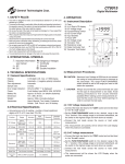
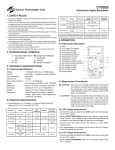
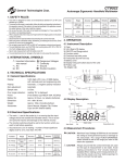
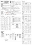
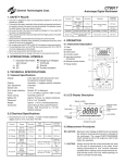
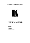
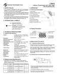
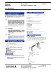
TA105
General Technologies Corp.
Laser Optical Tachometer
1. SAFETY RULES
4. OPERATION
• This Instrument is designed for indoor use at temperatures
between 32°F to 122°F (0°C to 50°C), altitudes up to 6500 ft.
(2,000 m), and 10% to 90% relative humidity.
• To ensure that the instrument is used safely, follow all safety and
operating instructions in this manual. If the instrument is not used
as described in this operation manual, the safety features of this
device might be impaired.
• To avoid personal injuries and damage to the instrument use
extreme caution when working around hot or moving objects or
machinery like: radiators, exhaust manifolds, catalytic converters,
drive belts, fly wheels, etc.
4.1 Instrument Description
1) Laser output
2) Laser warning symbol
3) Measurement button
4) Function switch
5) Memory button
6) Digital display
7) Battery compartment cover
2. INTERNATIONAL SYMBOLS
�
Important information
Refer to the User’s Manual
4.2 Display Description
CAUTION: Laser Radiation
AVOID DIRECT EYE EXPOSURE
1mW Output at 630-670 nm
Class II Laser Product
3. TECHNICAL SPECIFICATIONS
3.1 General Specifications
Display:
5 digits 0.7” (16mm) LCD, Max. of
99999 display, with measuring unit indicator and Laser On Target indicator
Resolution:
Operating Temperature:
Response time:
Range Selection:
Memory:
±(0.05%+1 Digit)
32°F to 122°F (0°C to 50°C)
0.5 sec. (over 120 RPM)
Auto Ranging
Max. Value, Min. Value and Last
Value stored automatically in memory
2” to 20” (50 mm to 500 mm)
Laser Diode, < 1mW output
wavelength 630-670 nm, Class II
Distance to target:
Laser Pointer:
Power Source:
4 x 1.5 V type AA/UM3 or equivalent
Battery life:
Dimensions:
Weight:
Approx. 5 hours.(w/alkaline batteries)
6.3”x 2.8”x 1.5” (160 x 72x 37 mm)
6.96 oz. (200 g) with battery.
Accesories:
Soft Pouch, 23.5” (600 mm) long reflective tape,4 x 1.5 V alkaline battery, and
User’s Manual
4.3 Measurement Procedures
�
CAUTION: Avoid contact with moving and hot
components, to prevent personal
injury or damage to the instrument.
�
CAUTION: Laser Radiation is emitted
Avoid direct eye contact
4.3.1 RPM Measurement
3.2 Measurement Specifications
• Accuracies are ±(% of reading + number of least significant digits) at 23°C ±5°C ambient temperature, with less than 75% RH.
Function
Range
Acuracy
2.5 to 999.9 RPM
RPM
0.1 RPM
±(0.05%+1 Digit)
1000 to 99,999 RPM
TOT
(total revolutions)
Resolution
1 to 99,999 RPM
1 RPM
±(0.05%+1 Digit)
1 RPM
• Apply a reflective mark or a piece of reflective tape to the
rotating object under measurement.
• Slide the function switch to the “RPM” position
• Press the measurement button and aim the light beam to the
reflective mark or tape on the rotating object.
• Verify that the “On Target Indicator“ appears on the display,
indicating that the instrument is detecting the rotation of the
object and the reflective mark on it.
• Proceed to read the RPM on the digital display.
4.3.2 TOT (Total revolutions) function
5. MAINTENANCE
• Apply a reflective mark or a piece of reflective tape to the
rotating object under measurement.
5.1 Battery Replacement
• Slide the function switch to the “TOT” position
• Press the measurement button and aim the light beam to the
reflective mark or tape on the rotating object.
• When the battery is low and needs to be replaced, the “Low Bat-
• Verify that the “On Target Indicator“ appears on the display,
indicating that the instrument is detecting the rotation of the
object and the reflective mark on it.
• Proceed to read the total revolutions on the digital display.
4.3.3 Reflective marks
• Cut a 1/2” length of the reflective tape provided, peel off the
back to expose the adhesive, and attach it to the rotating part
or shaft to measure, observing the following recommendations:
- The non-reflective area must always be smaller that the
reflective piece of tape.
- If the object or shaft to measure is reflective, it must first be
covered with a black tape or painted black before attaching
the reflective tape.
- Before applying the tape ensure that the surface is clean
and smooth
4.3.4 Very low RPM measurements
The response time will vary with the rotational speed being
measured. Therefore when measuring very slow rotating parts, it
may be advantageous to follow the procedure below to increase
the update rate of the measurement:
• Depending on the size of the rotating object or shaft,
attach multiples reflective marks, evenly spaced along its
circumference.
• Proceed to measure RPM as described in 4.3.1, and divide the
reading by the number of reflective marks, in order to obtain the
correct RPM.
tery Warning” symbol will appear on the lower left hand side of
the display.
• To replace the battery, remove the screw and open the battery
compartment cover (located at the back of the unit), and remove
the battery.
• Replace with 4 x 1.5 V type AA/UM3 or equivalent observing the
proper polarity of each battery as indicated at the bottom of the
battery compartment.
• Close the battery cover, and replace the screw.
5.2 Cleaning
5.2.1 Lens cleaning
Debris or dirt on the lens may cause obstruction and impede the
working of the tachometer. If this occurs, either wipe the lens with
a Q-tip (moistened with water only) or blow off the loose particles
with clean compressed air. Do not use solvent on the lenses, as it
may become damage.
5.2.2 Exterior cleaning
Periodically wipe the case with a soft damp cloth and mild household
cleanser. Do not use abrasives or solvents. Ensure that no water gets
inside the instrument to prevent possible shorts and damage.
6. WARRANTY
One year limited warranty, excluding batteries and fuses. For
details see Standard Warranty Information on our web page or you
may request a printed copy.
4.4 Other Functions
4.4.1 Display Hold
• The instrument will automatically hold the last reading
immediately after the “On Target Indicator” on the display
turns off, and hold it while the “Measurement button” is pressed.
4.4.2 MEM function
In every measuring cycle (pressing the measuring button,
obtaining a reading, and then releasing the button), the instrument
will automatically store in its internal memory the Maximum,
Minimum and Last value. To retrieve the values in memory follow
the procedure described below:
• With the instrument off press and hold down the “MEM” button
to display the Maximum value stored in memory. Display
screens will alternate between “UP” (maximum) and the stored
maximum reading. Note the value and release the “MEM”
button.
• Pressing and holding again the “MEM” button will display the
Minimum value stored in memory. Display screens will alternate
between “dn” (minimum) and the stored minimum reading. Note
the value and release the “MEM” button.
• Pressing and holding again the “MEM” button will display
the last reading value stored in memory. Display screens
will alternate between “LA” (Last reading) and the stored last
reading value. Note the value and release the “MEM” button.
This memory retrieval cycle will keep repeating in the order
detailed above.
Notes: The values stored in memory will be retained until a new
measurement cycle is performed.
Removing the batteries, or low batteries will cause all
values stored in memory to be erased.
General Technologies Corp.
#121 - 7350 72nd Street
Delta, BC
Canada V4G 1H9
Tel.: (604) 952-6699
Fax: (604) 952-6690
www.generaltechnologies.net
© Copyright 2004 General Technologies