1
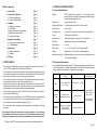
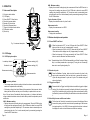
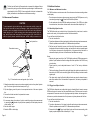
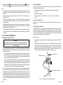
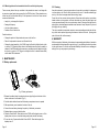
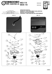
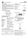
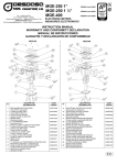
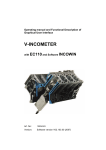
User’s Handbook
TA300
Diesel EngineTachometer
Table of contents.
2. TECHNICAL SPECIFICATIONS
1. Safety Rules
Page 1
2. Technical Specifications
Page 2
2.1 General specifications
2.2 Electrical Specifications
Page 2
Page 2
3. Operation
Page 3
3.1 Instrument description
3.2 LCD Display
3.3 Buttons description and operation
3.4 Measurement procedures
3.5 Additional functions
Page
Page
Page
Page
Page
3
3
4
5
6
2.1 General Specifications
Display: LCD 4½ Segment main readout, 2 x 3½ for maximum and
minimum readout, indicators for low battery, number of cycles
functions and measurement units.
Update rate:
3 per second (for LCD).
Engine system Comp. Fuel injection pump with lines for each cylinder.
Engine cycles:
2 and 4 cycles.
Fuel injection line:
Up to 9 mm dia. (Depending on piezoelectric sensor used)
Power: 9 Volt battery, type MN1604.
4. Application information
Page 7
Auto power off:
Automatically powers off after 3 min. of no operation.
4.1 Using the piezoelectric sensor
4.2 Troubleshooting
Page 7
Page 8
Battery life:
Approximately. 30 hours. (w/alkaline battery).
Cable length:
6’ (1.8 m)
5. Maintenance
Page 9
5.1 Battery replacement
5.2 Cleaning
Page 9
Page 10
Dimensions: 6” x 4” x 1.5” (158 x 100 x 37 mm) without cable.
Weight: Approximately. 14 Oz. or 406 g. (Including battery).
6. Warranty
Page 10
Included accessories:
Padded hard carrying case, user’s manual, rubber holster and
1 x 9 Volt alkaline battery.
1. SAFETY RULES
• This instrument is designed for indoor use at temperatures between 32° and 104° F
(0°C and 40°C) and altitudes up to 6500 ft (2,000 meters).
• To ensure that the instrument is used safely, follow all safety and operating instructions
in this operation manual. If the instrument is not used as described in this operation
manual, the safety features of this instrument may be impaired.
2.2 Electrical Specifications
• The specifications below are typical at 23° C, and will vary slightly from device to device,
and with temperature. The input voltage should not exceed the indicated maximum
values, to prevent personal injury or damage to the instrument.
Function
• Do not use the instrument if the instrument, the cables or the piezoelectric pickup, or
if you suspect that the instrument is not operating properly.
• When using the instrument, keep away from moving parts (fan, drive belts, etc) and
hot objects (exhaust pipes, muffler , catalytic converter, etc), to avoid personal injuries
and damage to the instrument, the cable or piezoelectric sensor.
• Do not connect or apply more than 42 VDC or any AC current directly to the connectors or the piezoelectric pickup.
• At all times, to avoid electrical shock, use CAUTION when working with electrical
circuits above 60V DC or 25V AC rms. Such voltages pose a shock hazard.
• Do not operate this instrument with the battery cover off.
• To avoid electrical shock or damage to the instrument, do not exceed the specified
input limits.
RPM
Measurement
Range
Accuracy/Repetitivity
100 to 19999 RPM
2 and 4 cycles
Accuracy: 0.1% ± 1 LSD
Sensitivity
Adjust
Signal sensitivity
adjustable from 1 to 10
Default setting: 5
Trigger Level
Adjust
Trigger level adjustable
from 20% to 80%
of peak input signal
Default setting: 50%
Input
Characteristics
Input Impedance:
2 MΩ minimum +
100 pF (Max).
Input Protection:
± 42 VDC Max.
Exceeding the limits listed above when using this apparatus, or not observing
the precautions listed above can expose you to physical injury and permanently
damage your instrument and/or parts and components of the vehicle under test.
“V Ready” and “GTC” are registered trademarks of General Technologies Corp.
Page 2
3. OPERATION
MIN - Minimum reading
• Displays the minimum reading during the measurement. When the RPM function is
being used the readings are shown in 10s of RPM, and to obtain the correct RPM
readings they should be multiplied by 10. The minimum value is automatically reset
when turning the unit off or it can be manually reset by momentarily pressing the Power
On/Off / Reset button.
3.1 Instrument Description
1)
2)
3)
4)
5)
6)
7)
8)
9)
Protective rubber holster
LCD Display
Power ON/OFF / Reset button
Sensitivity Increase button
Number of Cycles button
Sensitivity Decrease button
Trigger Level Adjust function button
Piezoelectric sensor
Gound clip
Cycles - Number of Cycles
• Displays the selected number of cycles: 2 and 4.
Sensitivity
Increase
Number of
Cycles
Trigger Level
Adjust
Sensitivity
Decrease
Measurement units
• Displays the measurement unit: RPM
Measurement reading
• Displays the measurement.
3.3 Buttons description and operation
3.3.1 Power ON/OFF and Reset
Fig. 1 - Instrument description
• When the instrument is OFF, to turn it ON press the Power ON/OFF / Reset
button until the unit turns on (in approximately 1 second).
• When the instrument is ON, to turn it OFF press and hold the Power ON/OFF
/ Reset button until the display turns off (in approximately 3 seconds).
3.2 LCD Display
• When the instrument is ON, press momentarily the Power ON/OFF / Reset
button to reset the Maximum and Minimum values.
3.2.1 LCD Display description
Low battery indicator
Maximum reading (x10)
Number of cycles
Minimum reading (x10)
3.3.2 Number of cycles
Measurement reading
Measurement units
Fig. 2 - LCD Display
Low battery indicator
• This message warns the battery voltage is below the minimum recommended and it
needs to be replaced with a new battery.
• If the battery voltage is low, but still allows for the operation of the instrument, the low
battery indicator will turn and stay on until the battery is replaced with a new one.
Note: If the unit turns off immediately after being turned on, it indicates that battery
voltage is below the absolute minimum, and the battery should be replaced to prevent
malfunction.
MAX - Maximum reading
• Displays the maximum reading during the measurement. When the RPM function
is being used the readings are shown in 10s of RPM and to obtain the correct RPM
readings they should be multiplied by 10. The maximum value is automatically reset
when turning the unit off or it can be manually reset by momentarily pressing the
Power On/Off / Reset button.
Page 3
Note: To extend battery life, the TA300 will automatically turn off after 3 minutes of being
idle (i.e. no button pressed and no input signal). Turning the unit off manually,
when not in use will prolong battery life.
• P
ress the Number of cycles button to select the number of cycles for the
engine under measurement. Each time the button is pressed the number of
cycles will change between 2 cycles and 4 cycles. The selected setting will
show on the display.
3.3.3 Trigger Level Adjust
• Press and hold the Trigger Level Adjust button to enable the trigger level adjust
function. After this button is pressed, the display will show the current trigger
level (50% is the default setting), and the trigger level can be adjusted by using
the Sensitivity Increase or Sensitivity Decrease buttons to increase or decrease
it.
3.3.4 Sensitivity Increase and Decrease buttons
• The first time the Sensitivity Increase button is pressed, the display will show
the sensitivity setting, and each time the button is pressed again it will increase
the signal sensitivity of the TA300. A few seconds after the button is released
the display will resume to show Maximum and Minimum readings.
Page 4
• The first time the Sensitivity Decrease button is pressed, the display will show
the sensitivity setting, each time the button is pressed again it will decrease the
signal sensitivity of the TA300. A few seconds after the button is released the
display will resume to show Maximum and Minimum readings.
3.5 Additional functions
3.5.1 Minimum and Maximum functions
The TA300 maintains a continuous record of the minimum and maximum readings shown
on the display.
• The minimum and maximum values are reset upon turning the TA300 power on, or by
momentarily pressing the
(Power On/Off and Reset) button.
3.4 Measurement Procedures
CAUTION
To avoid personal injuries and damage to the instrument carefully inspect the
fuel injection lines and fuel pump for damage or leaks, and avoid using this instrument in case any damage or leaks are found. Never touch the piezoelectric
sensor during a test. Wear insulating gloves when working around high voltage, and hot parts, and keep away from moving parts (fan, drive belts, etc)
and hot objects (exhaust manifold and pipes, muffler, catalytic converter, etc.)
• For the tachometer function (RPM) all readings are shown in 10s of RPM, so to obtain
the actual values, the minimum and maximum values should be multiplied by 10.
3.5.2 Sensitivity Adjust function
The TA300 allows the user to adjust the level of signal sensitivity it can detect, in order to
match a wide variety of fuel pressures and fuel lines characteristics.
To use the Sensitivity Adjust function:
1-Turn the instrument on.
Fuel injection line
Piezoelectric sensor
2-To perform adjustments of the signal sensitivity while performing actual measurements,
follow the procedure as described in ‘3.4 Measurement procedures’.
4-The first time the Sensitivity Increase or the Sensitivity Decrease button is pressed,
the display will show the sensitivity setting, and each time the button is pressed again
it will increase or decrease the signal sensitivity. A few seconds after the button is
released the display will return to show Maximum and Minimum readings.
Notes:
• Adjusting the signal sensitivity of the TA300 while performing RPM measurements,
provides quick feedback on how this setting affects the response of the TA300 in any
given situation.
Ground clip
• S ignal sensitivity can be adjusted between 1 and 10. The factory calibration
value is 5.
• The lower the value of the sensitivity setting the bigger the signal input needs to be for
detection by the TA300, and converserly higher sensitivity settings can detect smaller
signals input.
Fig. 3 - Piezoelectric sensor and ground clip on fuel line
1-Clamp the piezoelectric sensor onto a clean unpainted section of any diesel injection
pipe. Do not over tighten the thumb screw (see Fig. 3)
2-Clip the alligator ground clip onto a clean unpainted section of the same injection
line.
3-Connect the forked terminal to the piezoelectric sensor.
4-Turn the instrument on.
5-If necessary change the number of cycles to match the engine under measurement
by pressing the
(Number of cycles) button repeatedly until the display shows the
correct setting.
4-Start the diesel engine.
6-Read the RPM on the display.
Page 5
• The values set by using the Sensitivity Adjust function are stored in internal memory,
and will be retained even if the instrument is powered off, the battery is depleted or
removed.
3.5.3 Trigger Level Adjust function
The TA300 also allows the user to adjust the trigger (or threshold) level it uses to measure
RPM from the signal it receives from the piezoelectric sensor. This feature can be used to
compensate for excessive noise in the signal generated by vibration, electromagnetic interference or particular characteristics of fuel pressure, injection patterns and fuel lines.
To use the Sensitivity Adjust function:
1-Turn the instrument on.
2-To perform adjustments of the trigger level while performing actual measurements,
follow the procedure as described in ‘3.4 Measurement procedures’.
3-Press and hold the
(Trigger Level Adjust) button until the minimum reading in the
display is replaced by a number followed by a ‘%’ sign.
Page 6
4-While holding the
Adjust increase) or
(Trigger Level Adjust) button pressed, use the
(Sensitivity
(Sensitivity Adjust decrease) buttons to adjust the % value.
Notes:
• Adjusting the trigger level of the TA300 while performing RPM measurements, provides
quick feedback on how this setting affects the response of the TA300 in any given
situation.
• The trigger level can be adjusted between 20% and 80%. The default value for the
trigger level is 50%.
• For example, if the trigger level is set to 70%, the TA300 will register an engine cycle
when the signal level from the piezoelectric sensor reaches or exceeds 70% of the
maximum signal.
• Higher trigger levels increases the noise rejection, and lower trigger level will help in
measuring RPM when dealing with inconsistent injection pulses. For most cases the
default 50% level is the optimal value.
• The values set by using the Trigger Level Adjust function are stored in internal memory,
and will be retained even if the instrument is powered off, the battery is depleted or
is removed.
4. Application information
4.1 Using the piezoelectric sensor
Important
The piezoelectric sensor is constructed with an special piezoelectric
ceramic material and it can be easily damaged by impacts or if excessive
pressure is applied.
1-For the piezoelectric sensor to work, it requires that a good electrical connection be
established between the center part of the sensor, and the ground clip. This can be
achieved in two ways:
• Fit the piezoelectric sensor to a clean unpainted section of an injection line. Then
connect the ground clip to that same clean section of the injection line as shown in
Fig. 3. or to a convenient ground in the engine. If necessary scrape and sandpaper
the line in order to expose the metal surface.
4.2 Troubleshooting
The main factors that may cause unstable, erroneous or in some cases prevent the TA300
from obtaining a reading at all are:
• Poor electrical contact between the center of the piezoelectric sensor and the
ground clip.
• Engine/fuel line vibration.
• Weak signal due to the characteristics of the fuel line or the fuel injection
pump.
4.2.1 Poor electrical contact
Please refer to ‘4.1 Using the piezoelectric sensor’ for detailed instructions on how to use
the sensor.
4.2.2 Engine/fuel line vibration
The piezoelectric sensor is specially designed to detect the expansion of the fuel line cause
by the pulses of pressure generated by the fuel when injected into the cylinder. However
under some conditions the vibration of the engine and fuel line may cause an excessive
amount of noise in the signal, in which cases the TA300 may not recognize the signal and
generate incorrect RPM readings or no reading at all.
Possible solutions:
• Use the Trigger Level Adjust function to change the trigger level until a stable RPM is
obtained.
• Sometimes the vibration noise may be caused or magnified by the minute ‘jerking’ of
the cable connecting to the piezoelectric sensor to the TA300, and providing some
strain relief may be of help in obtaining RPM readings. To provide strain relief to the
piezoelectric sensor, attach the red wire (which is connected to the sensor ) to the
same fuel line using electrical tape or a cable tie, as shown in Fig 4.
Piezoelectric sensor
Fuel injection line
• If you do not wish to scrape the fuel line, you could tightly wrap a piece of aluminum
foil around the pipe and clamp the piezoelectric sensor over this foil. Make the foil
wrap long enough to allow placing of the ground clip on the same piece of foil. Use
of aluminum foil will often fix problems due to bad electrical connections between
the piezoelectric sensor and the injection pipe and ground clip.
2- Do not over tighten the clamp. Use of excessive force or tools such as pliers to tighten
the clamp will result in damage to the piezoelectric sensor and void the guarantee.
3-If not already connected, locate the forked terminal at the end of the red wire (near
to the alligator ground clip) and push it under the flat head of the connector pin at the
corner of the piezoelectric sensor. This connector pin is the one with a coil spring. You
will see that this spring presses a conical washer against the flat pin head. The forked
terminal must be inserted between this washer and the flat pin head. Hook up is now
complete.
Page 7
Electrical tape or cable tie
Fig. 4 - Strain relief setup for piezoelectric sensor
Page 8
4.2.3 Weak signal due to the characteristics fuel line or fuel injection pump
5.2 Cleaning
There are many factors that may contribute to the piezoelectric sensor in not being able
to generate a signal (pulse) strong enough for the TA300 to detect. These situations may
cause low, slow or inconsistent built up of fuel pressure in the fuel line. Some common
causes are listed below:
Keep the instrument in its carrying case when not in use and do not subject it to dampness
or severe heat or cold. Do not use the instrument in the rain, if it should accidentally get
wet, dry it off with a clean paper towel before storing it away.
• Leaky, dirty or damaged fuel injectors.
• Damaged fuel pump.
• Very low cylinder pressure.
Protect the unit from contact with any solvents. Never clean with a solvent or petroleum
based medium such as gasoline, as these chemicals may attack the plastic parts and
cause permanent damage. Never use an abrasive cleaner. Cleaning should be limited to
wiping with a clean damp paper towel and a small amount of soap if required. Dry the unit
thoroughly after any cleaning.
The unit is a sealed instrument and contains no user serviceable parts other than the battery, which can be replaced by opening the drawer on the back of the unit. Opening other
parts of the unit will void the warranty.
• Presence of air in the fuel line.
Possible solutions:
• Change the position of the piezoelectric sensor in the fuel line.
6. WARRANTY
• Place of the piezoelectric sensor to a different fuel line.
• Change the signal sensitivity of the TA300 using the Sensitivity Adjust function (refer
to section ‘3.5.2 Sensitivity Adjust function’ for detailed instructions) until a reading is
obtained. If the RPM readings are erroneous or unstable proceed to adjust the trigger
level (refer to section ‘3.5.3 Trigger Level Adjust function’ for detailed instructions)
until a stable RPM is obtained..
With the exception of the battery, this instrument is warranted against defects of material or
workmanship which develop within a period of one (1) year following the date of purchase
by the original owner. For details see Standard Warranty Information on our web page at
www.gtc.ca or you may request a printed copy.
5. Maintenance
5.1 Battery replacement
2
1
3
Fig 5 - Battery replacement
1-Release the rubber holster from plastic enclosure by pulling from the bottom of the
holster as shown in the illustration (Fig. 5)
2-Push the rubber holster forward until the battery compartment cover is exposed
3-Slide open battery cover located at the back of the unit.
4-Connect the new battery observing the polarity of the battery connectors.
5-Replace battery cover and rubber holster.
4-Press the Power On/Off / Reset button on the TA300 until the display turns on. If the
display does not turn on, check the battery polarity and reinstall if necessary.
5-To turn the unit off, press and hold the Power On/Off / Reset button again the
displays turn off.
Page 9
Page 10
Part # TA300MN1005EN
General Technologies Corp.
#121 - 7350 72nd Street
Delta, BC Canada V4G 1H9
Tel.: (604) 952-6699
Fax: (604) 952-6690
www.gtc.ca
© 2010 General Technologies Corp.
Printed in Canada