1
User Manual
VB0009
VB0008
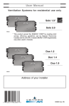
Ventilation Systems for residential use only
MODELS
Solo 1.5
Solo 2.0
Duo 1.2
Duo 1.4
Duo 1.9
Address of your installer
03329-04/01/12
ABOUT THIS MANUAL/PRODUCT
The purpose of this manual is to help you with the use of your unit. Section 2
(How to Operate the Unit Using Controls) shows you how you can operate the
unit in no time. Section 3 deals with maintenance and explains how to maintain
the unit to ensure maximum operation and performance. In the other sections, for
example troubleshooting, you will learn how to solve minor problems (Section 4);
plus other important information which we urge you to read.
In simplifying explanations, all drawings (figures) in this manual show the unit
installed in the “normal” position. However, please note that your unit can be
installed in either the “normal” or “reverse” (upside down) position. Several models
are described in this publication. Some details of your unit may be slightly
different than the ones shown, as the illustrations are typical ones.
We welcome any suggestions you may have concerning this manual and/or the
unit, and we would appreciate hearing your comments on ways to better serve
you. Please forward all correspondence to us at the address indicated on the
product’s registration card included with this manual.
This manual uses the following symbols to emphasize particular information:
! WARNING
Identifies an instruction which, if not followed, might cause serious
personal injuries including possibility of death.
0
CAUTION
Denotes an instruction which, if not followed, may severely damage the
unit and/or its components.
NOTE: Indicates supplementary information needed to fully complete an instruction.
Finally, we want to congratulate you on your purchase of this excellent unit which
will allow you and your family to enjoy fresh air throughout your home for years
to come!
CAUTION
Some activities create dust or vapors which may damage your unit. You
must therefore turn off and unplug your unit in the following situations:
• major renovation work
• housing construction
• sanding (e.g. gypsum joints, etc.)
• varnishing
During very heavy snowstorms, the unit should also be turned off to avoid
problems caused by snow entering the unit, even if it is equipped with an
anti-gust intake hood.
2
TABLE OF CONTENTS
1.0
YOUR UNIT AND ITS PURPOSE . . . . . . . . . . . . . . . . . . . . . . . . .4
1.1
1.2
1.3
1.4
1.5
1.6
Unit Description . . . . . . . . . . . . . . . . . . . . . . . . . . . . . . . .4
Purpose of the Ventilation System . . . . . . . . . . . . . . . . . .4
Recovery . . . . . . . . . . . . . . . . . . . . . . . . . . . . . . . . . . . . .5
Filtration . . . . . . . . . . . . . . . . . . . . . . . . . . . . . . . . . . . . .6
Defrost Mode . . . . . . . . . . . . . . . . . . . . . . . . . . . . . . . . . .6
Specifications . . . . . . . . . . . . . . . . . . . . . . . . . . . . . . . . .6
2.0
HOW TO OPERATE THE UNIT USING CONTROLS . . . . . . . . . . . . . .7
2.1
2.2
2.3
2.4
2.5
Instructions Regarding your Control Devices . . . . . . . . .7-8
Using the Venta Main Control . . . . . . . . . . . . . . . . . . . . .9
Using the Supra Main Control . . . . . . . . . . . . . . . . . .10-11
Using the Ultima Main Control . . . . . . . . . . . . . . . . . .12-13
Using the Auxiliary Controls . . . . . . . . . . . . . . . . . . .14-15
3.0
MAINTENANCE . . . . . . . . . . . . . . . . . . . . . . . . . . . . . . . . . . .16
3.1
3.2
Every Three Months . . . . . . . . . . . . . . . . . . . . . . . . .16-17
Annual Maintenance (Fall) . . . . . . . . . . . . . . . . . . . .18-19
4.0
TROUBLESHOOTING . . . . . . . . . . . . . . . . . . . . . . . . . . . . . . .20
3
1.0
YOUR UNIT AND ITS PURPOSE
1.1
UNIT DESCRIPTION
4. Heat recovery core or
thermal wheel
5. Optional filter
1. Basic filters
2. Blower
3. Condensation tray
(on Solo unit only)
*Units shown in normal position. Can also be installed upside down.
SOLO
DUO
5
1
4
2
2
1
1
5
3
1
VB0057
VB0056
1.2
4
PURPOSE OF THE VENTILATION SYSTEM
Your ventilation system is designed to provide fresh air, warmed outdoor air to
your home while exhausting stale, humid air from your home. By eliminating
accumulated pollutants and humidity, it maintains an optimum air quality and an
ideal relative humidity.
VH0006
NOTES: 1. Shown with a forced air system. Can also operate on its own.
2. Installation may vary according to the model number and the position
(normal or reverse) in which the unit is installed.
4
1.3
RECOVERY
A) Units with a heat recovery core (Solo units) are designed specifically to
control excess humidity and reduce ventilation costs by recovering the heat
energy from the exhausted air, and using that same heat energy to warm
the fresh air being supplied. This heat recovery process is accomplished in
such a way that the stale air is never mixed with the fresh air.
Example (in winter):
FRESH AIR TO BUILDING 16°C
INSIDE
OUTSIDE
STALE AIR TO OUTSIDE 6°C
FRESH AIR FROM OUTSIDE 0°C
STALE AIR FROM BUILDING 22°C
VF0026
B) Units equipped with a thermal wheel (Duo units) can reduce ventilation
costs in winter as well as in summer by maintaining indoor humidity level for
maximum comfort.
1. During the heating season, the unit draws the humidity and heat from the
stale air and transfers them, in part, to the cold air entering the house, thus
avoiding dryness problems and providing maximum comfort (Example 1).
2. During the cooling season, the unit reverses the process, preventing the
humidity from the outside air from entering into the house (Example 2).
Example 1
(in winter):
Example 2
(in summer with air conditioning):
Stale and dry air
from building
VF0030
Dry fresh air
from outside
18°C / 64°F
26°C / 79°F
INSIDE
32°C / 90°F
INSIDE
OUTSIDE
22°C / 72°F
0°C
OUTSIDE
Stale and humid
air from building
VF0031
Humidified fresh
air to building
Fresh humid air
from outside
Heating season
27°C / 81°F
Dehumidified fresh
air to building
Cooling season
5
1.4
FILTRATION (only applicable to units operated with Ultima main control)
A) Basic filtration:
While in filtration mode, the unit ceases to exchange air with the exterior.
Continuous circulation and a mechanical filter ensure the purification of the
ambient air inside the house. The mechanical filter traps dust particles visible
to the eye.
B) Optional filters (add-on to the basic filtration):
• Pleated: A second stage filter to trap dust particles.
• Electronic: Acts as the pleated model with increased efficiency.
• Activated carbon: Traps dust particles and odors.
1.5
DEFROST MODE
When the outside temperature is below -5°C (23°F), recovery (of heat or energy)
creates frost in the module. To maintain its proper operation, the unit is programmed
to defrost the recovery module. The defrost frequency varies according to the
outside temperature. Defrost lasts 6 minutes for Solo models and 9 minutes for
Duo models (or 10 minutes for all models if set on “Extented Defrost”). During
the defrost cycle, the unit shifts to maximum speed and the dampers close.
After defrosting, the unit returns to the operating mode selected by the user.
1.6
SPECIFICATIONS
Model
Width
Height
Depth
Weight
Electrical Supply
Power Consumption
Model
Width
Height
Depth
Weight
Electrical Supply
Power Consumption
Solo 1.5
Solo 2.0
30 1/4“ (768 mm)
16 1/2“ (419 mm)
17 1/4“ (438 mm)
71 lbs (32 kg)
120 V, 60 Hz
150 Watts
30 1/4“ (768 mm)
16 1/2“ (419 mm)
17 1/4“ (438 mm)
71 lbs (32 kg)
120 V, 60 Hz
240 Watts
Duo 1.2
Duo 1.4
Duo 1.9
30 1/4“ (768 mm)
16 1/2“ (419 mm)
17 1/4“ (438 mm)
79 lbs (36 kg)
120 V, 60 Hz
160 Watts
30 1/4“ (768 mm)
16 1/2“ (419 mm)
17 1/4“ (438 mm)
75 lbs (34 kg)
120 V, 60 Hz
160 Watts
30 1/4“ (768 mm)
16 1/2“ (419 mm)
17 1/4“ (438 mm)
77 lbs (35 kg)
120 V, 60 Hz
250 Watts
6
2.0
HOW TO OPERATE THE UNIT USING CONTROLS
2.1 INSTRUCTIONS REGARDING YOUR CONTROL DEVICES
Determine which controls are installed in your house and identify them in the
following tables (this page and the following page). Then, you can proceed to the
pages indicated to learn how to CONTROL your unit.
MAIN CONTROLS
Venta main control . . . . . . . . . . . . . . . . . . .Page 9
VC0010
Supra main control . . . . . . . . . . . . . . . . . .Page 10
VC0011
Ultima main control . . . . . . . . . . . . . . . . .Page 12
VC0013
7
2.1 INSTRUCTIONS REGARDING YOUR CONTROL DEVICES (CONT’D)
AUXILIARY CONTROLS
20-min. wireless push-button timer . . . . . . .Page 14
VC0006
20/40/60-min. push-button timer . . . . . . . . .Page 14
20 min.
40 min.
60 min.
VC0007
TURN
PAST
20
OFF
10
60-min. crank timer . . . . . . . . . . . . . . . . . . .Page 15
20
30
60
40
50
VC0017
Dehumidistat . . . . . . . . . . . . . . . . . . . . . . .Page 15
VC0009
8
2.2
USING THE VENTA MAIN CONTROL
Location:Located in the busiest area of the house.
Purpose: To adjust air supply and select desired indoor humidity level.
ADJUSTING
THE
AIR SUPPLY CONTROL
a) Select speed “MIN.” or “MAX.” using
switch A (as shown on diagram).
• When “MIN.” (minimum speed) is
selected, if the knob B is set above
the click, the unit will exchange in
low speed with the outside and if it
is set below the click, the unit will
exchange on high speed with the
outside until the desired humidity
B
level has been reached.
• When “MAX.” (maximum speed) is
selected, the unit will exchange on
VC0010
high speed with the outside either
if he knob B is set below of above the click.
A
b) To turn the unit off, place selector A at the “OFF” position.
Optional controls, however, may still be active.
ADJUSTING
THE
HUMIDITY CONTROL
Setting during the summer months:
During this period, unless being afflicted by breathing problems, using the
humidity control is unnecessary. Set switch A to OFF. (Do not exchange in day
time; exchange at night time, if cool outside, or if it is not rainning.)
Setting during the fall, winter and spring months:
1) Determine the humidity level in your house (bring the knob B counterclockwise
to 20%, then bring it back clockwise slowly until you hear a “click”).
2) Set knob B to 1% under this temperature level or “click”.
NOTES: 1. Do not select a humidity level below 30%. This could lead to excessive
dryness in the air causing discomfort for the occupants.
2. When the humidity level is high, the unit automatically operates at
maximum speed. If you change the setting of your “AIR SUPPLY”
knob (B) at that time, it will remain at maximum speed until the humidity
level is reduced, and then switch to the desired setting.
It is possible (and normal) to experience condensation on your windows
when drastic changes in temperature happen (for example: -5°C (23°F) to
-20°C (-4°F) within few hours). In that case, we suggest waiting a few days
to allow the situation to stabilize.
9
2.3
USING THE SUPRA MAIN CONTROL
Location:Located in the busiest area of the house.
Purpose: To adjust air supply and select desired indoor humidity level.
ADJUSTING AIR SUPPLY CONTROL
a) Press “PUSH” (A) until the “MIN.”, “MAX.” or “INTERMITTENT” light
indicator appears.
C
D
• When “MIN.” (minimum speed) is
selected, if the knob B is set
above the click, the unit will
exchange in low speed with the
outside and if it is set below the
click, the unit will exchange on
high speed with the outside until
the desired humidity level has
been reached.
• When “MAX”. (maximum speed)
B
is selected, the unit will
exchange on high speed with
A
the outside either if he knob B is VC0011
set below of above the click.
• Select “INTERMITTENT” (20 minutes minimum speed exchange every
hour) when you are away from the house for a few days or when you
deem the inside air too dry.
b) To turn the unit off , press “PUSH” (A) until the “MIN.”, “MAX.” and
“INTERMITENT” light indicators are all turned off.
NOTE: Optional controls will still be active. (Indicator “C” will be the only one to
light up if an optional control is active).
ADJUSTING HUMIDITY CONTROL
Setting during the summer months:
Normally, excess humidity is not a problem during this period, which therefore
eliminates the need for the humidity control. Set knob B at the “SUMMER”
position during this period.
Setting during the fall, winter and spring months:
Ideally, maintain humidity level within the “Comfort Zone” (between 5°C and
-20°C), which is the dark area around knob B.
To reduce humidity level, turn knob B clockwise a notch below the click. The unit
will then switch to high speed, lighting up the humidity light (D indicator).When
this light goes "OFF" (after a few hours or a few days), repeat the same procedure
if excess humidity persists.
NOTE: If the air is too dry, set your knob B back to the “Comfort Zone” and use
INTERMITTENT or turn off the unit.
When the humidity light (D indicator) goes "ON", you can still change the
mode of operation but your change will take place only when the light goes OFF.
10
2.3
USING THE SUPRA MAIN CONTROL (cont’d)
UNDERSTANDING
THE LIGHT INDICATORS
LIGHTS UP when
the control has
detected excess
humidity. This forces
the motor to operate
at high speed. The
light indicator turns
off
when
the
humidity drops to
the level associated
with the temperature
selected on knob B.
LIGHTS UP when the system is
operating (exhausting stale air
from the house and drawing in
fresh air).
LIGHTS UP when you have
selected the intermittent mode.
FLASHES when maintenance
is required (see Section 3).
11
USING THE ULTIMA MAIN CONTROL
2.4
Location: Located in the busiest area of the house.
Purpose: To adjust air supply and eliminate offensive pollutants or to filter air
inside the house.
C
ADJUSTING
THE
D
AIR SUPPLY CONTROL
a) Press (A) until the “MIN.”, “MAX.” or
“INTERMITTENT” light indicator
appears.
•
Select “MIN.” (minimum speed)
GREEN light: To exchange air
with exterior (normal daily
operation).
RED light: To filter indoor air
allowing exchange with outside
air when necessary only (when
indoor humidity is too high).
B
A
VC0013
•
•
Select “MAX.” (maximum speed)
GREEN light: To evacuate excess of pollutants and humidity (parties,
odors, smoke, etc.)
RED light: To filter indoor air allowing exchange with outside air when
necessary only (when indoor humidity is too high).
Select “INTERMITTENT”.
GREEN light: To exchange air 20 minutes per hour (unit is OFF for the
rest of the time). Normally used when you are away from the house for
a few days or when you deem the inside air is too dry.
RED light: To filter indoor air for 40 minutes per hour (unit exchanges
air for the rest of the time). Normally used to filter air and allows
exchange with exterior at a pre-defined frequency.
b) To turn the unit off press (A) until the “MIN.”, “MAX.” and “INTERMITTENT”
light indicators are all turned off.
NOTE: Optional controls will still be active. (Indicator “C” will be the only one
to light up if an optional control is active).
12
2.4
USING THE ULTIMA MAIN CONTROL (cont’d)
ADJUSTING HUMIDITY CONTROL
Setting during the summer months:
Ideally, maintain humidity level within the “Comfort Zone” (between 5°C and
-20°C), which is the dark area around knob B.
To reduce humidity level, turn knob B clockwise a notch below the click. The unit
will then switch to high speed, lighting up the humidity light (D indicator).When
this light goes "OFF" (after a few hours or a few days), repeat the same procedure
if excess humidity persists.
NOTE: If the air is too dry, set your knob B back to the “Comfort Zone” and use
INTERMITTENT (red lights) or turn off the unit.
When the humidity light (D indicator) goes "ON", you can still change the
mode of operation but your change will take place only when the light goes OFF.
When the humidity light “D” goes "ON", you can still change the mode of
operation but your change will take place only when the light goes "OFF“.
UNDERSTANDING LIGHT INDICATORS
LIGHTS UP when
the control has
detected excess
humidity. This forces
the motor to operate
at high speed. The
light indicator turns
off
when
the
humidity drops to
the level associated
with the temperature
selected on knob B.
LIGHTS UP when the system is
operating (exhausting stale air
from the house and drawing in
fresh air).
LIGHTS UP when you have
selected the intermittent mode.
FLASHES when maintenance
is required (see Section 3).
13
2.5
USING THE AUXILIARY CONTROLS
A) TIMERS
Location: Located in the bathroom or in other locations where there is
temporary excess humidity or pollutants.
Purpose: To eliminate excess humidity produced by showers or other
periodic activities producing pollutants.
20-MINUTE WIRELESS PUSH-BUTTON TIMER:
Set the push-button to ON: The light indicator lights up for a
few seconds and the system exchanges air at high speed for
20 minutes.
NOTE: The pushbutton is powered using two 3-Volt lithium
batteries with an expected battery life of up to 3 years.
VC0006
Batteries replacement: When the batteries are low, the light indicator flashes
while activating the push-button.
Remove batteries
from this end
Open
VC0056
Open push-button
to access batteries.
Pry
Lift
VC0058
VC0057
Gently lift up end of
battery clamp. Slide
batteries out.
Install two Duracell,
type DL2032.
Batteries (+) side up.
20/40/60-MINUTE PUSH-BUTTON TIMER:
High speed activation times are in multiples of 20 minutes.
• Within 2 seconds, push one time for 20 minutes, two
times for 40 minutes, or three times for 60 minutes
activation. Indicator then lights up and the system
exchanges air at high speed.
• Every 5 seconds, the indicator light flashes one time to
indicate a 20-minute selection, two times for a 40-minute
and three times for a 60-minute selection.
• To stop activation, push one more time. Unit then returns
to its to previous setting.
14
20 min.
40 min.
60 min.
VC0007
2.5
USING THE AUXILIARY CONTROLS (cont’d)
A) TIMERS (CONT’D)
60-MINUTE CRANK TIMER:
This control makes the system operate at high speed for
periods varying from 10 to 60 minutes.
TURN
PAST
20
OFF
10
20
30
60
40
50
VC0017
B) DEHUMIDISTAT
Location: Located in the bathroom or in other locations where there is
temporary excess humidity.
Purpose: To eliminate excess humidity produced by showers or other
periodic activities producing humidity.
In the fall, winter and spring: Adjust the knob to the desired maximum
humidity level.
NOTE: Do not select a humidity level below 30%.
This could lead to excessive dryness in the
air causing discomfort for the occupants.
In the summer: Adjust the knob to the
“SUMMER” position.
VC0009
15
3.0
MAINTENANCE
! WARNING
Dangerous voltage may be present. During maintenance and repairs, the
unit must always be turned off, then unplugged.
We take great care to minimize sharp edges; however, please proceed
with caution when handling all components.
0
NOTE: Unit is shown in normal position but can be installed in either the
“normal” or “reverse” (upside down) position.
MAINTENANCE PROCEDURE:
EVERY THREE MONTHS
3.1
Regular maintenance should be performed every 3 months. Annual maintenance
should also take place every fall season.
1.
Disconnect the power supply.
2. Unlatch the door. Lift the pannel
towards you. Hold it firmly and hit
on the right side of the pannel. The
door should slide to the left.
VD0005
3. Clean the inside of the door with a
damp cloth.
4. A)
Clean the basic filters
• Remove filters.
• Vacuum to remove most
of the dust.
• Wash with a mixture of
warm water and mild
soap. You may add bleach
if you wish to disinfect
(one tablespoon per gallon).
Rinse thoroughly. Shake
filters to remove excess
water and let dry.
VD0144
Optional
SOLO
VO0051
Basic
NOTE: Washing the filters in the top
tray of the dishwasher is possible,
but the aluminum frame might
tarnish.
DUO
B) Replace the optional filters if
necessary
• Do not wash in water.
VO0052
Basic
16
Optional
3.1
EVERY THREE MONTHS (CONT’D)
5. Clean the condensation tray with a damp
cloth.
6. Check the exterior air intake hood:
• Make sure there are no leaves, twigs, ice
or snow that could be drawn into the
vent.
• Clean if necessary.
VD0141
CAUTION
Even a partial blocking of this air vent could cause the unit to malfunction.
7. Reassemble the components:
• Filters
• Door (The door is secured when you hear a click.)
8. Reconnect the power supply.
17
ANNUAL MAINTENANCE (FALL)
3.2
! WARNING
Dangerous voltage may be present. During maintenance and repairs, the
unit must always be turned off, then unplugged.
We take great care to minimize sharp edges; however, please proceed
with caution when handling all components.
0
Repeat steps 1 to 6 from the previous Section and continue with the following steps:
CAUTION
Handle the recovery module with care.
1.
Clean the recovery module
A-
Polypropylene core (Solo)
•
Remove the recovery core.
•
Let it soak in a mixture of cold or
lukewarm water and mild soap
(dishwashing liquid).
•
Rinse thoroughly.
•
Shake the core to remove excess
water and let it dry.
B-
SOLO
VD0142
Thermal wheel (Duo)
CAUTION
This type of recovery module cannot be washed with water.
DUO
•
•
•
Disconnect the thermal wheel wires.
Remove the thermal wheel.
Remove dust using a vacuum
cleaner with a soft brush attachment.
VD0143
2. Clean the centrifugal fan wheels
A
Disconnect the fan motor wires.
VE0067
18
ANNUAL MAINTENANCE (FALL) (CONT’D)
3.2
2. Clean the centrifugal fan wheels (cont’d)
B
Disconnect the rod activating
the square damper.
C
Remove the two screws securing
the fan assembly.
D
C
D
Pull the fan assembly out of the
unit.
B
VO0050
Check for any dust accumulation
on the blades.
E
CAUTION
Do not oil the motor! It is already permanently
lubricated.
VD0139
Clean with a small brush
if necessary.
F
VD0106
3. Put the components back in place (cf: section 1.1.):
•
•
•
•
Fan assembly (screws, damper rod, fan motor wires)
Recovery module
Filters
Door
4. Reconnect the power supply.
19
4.0
TROUBLESHOOTING
If you think your unit is malfunctioning, check some of the following.
TYPE OF PROBLEM
TRY THIS...
1
Nothing works.
• See if the unit is plugged in.
• See if the unit is receiving power
from the house circuit breaker or fuse.
2
All light indicators on the wall control
system are flashing
(every 8 seconds).
• Unplug the unit, wait 30 seconds,
then reconnect. If the problem
continues, contact your installer.
3
Light indicator flashes or doesn’t light
while activating the
wireless push button.
• Open the push button casing and
change the batteries. They are low
(see Section 2.5).
4
Condensation on windows.
(Air too humid.)
• Adjust the humidity control knob as
per instructions (see Section 2).
• Operate the unit at maximum speed
(MAX.) during activities generating
excess humidity (family gatherings,
extra cooking, etc.).
• Leave curtains half-open to allow air
circulation.
• Store all firewood in a close room with
a dehumidifier or in a well ventilated
room, or store the wood outside.
• Keep the temperature in your house
above 18°C (64°F).
5
Air too dry.
• Do not adjust your humidity control
below -20° C (30%).
• Operate the unit at low speed (MIN.).
• Temporarily switch to the intermittent
mode.
• Temporarily use a humidifier.
6
Air too cold at the air supply grille.
• Make sure the outside hoods are not
blocked.
• Operate the unit at low speed (MIN.).
• Have the system’s balancing checked.
• Have the unit’s defrost system checked.
• Install a duct heater.
If the problem persists, contact your installer at the telephone number and
address indicated on the first page of this manual or call the following phone
number for assistance:
•
1-800-567-3855 (Canada and United States)
20