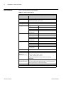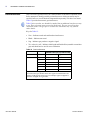
1
Protege ZM User Guide
PROTEGE ZM PORTABLE GAS
MONITOR
087-0047
Rev B
Protege ZM User Guide
PROTEGE ZM PORTABLE GAS MONITOR
087-0047
Rev B
© 2012 Scott Safety. SCOTT, the SCOTT SAFETY Logo, Protege, Proton, Scout,
Freedom, Masterdock are registered and/or unregistered marks of Scott Technologies,
Inc. or its affiliates.
All rights reserved. No part of this documentation may be reproduced in any form or
by any means or used to make any derivative work (such as translation,
transformation, or adaptation) without written permission from Scott Safety.
Scott Safety reserves the right to revise this documentation and to make changes in
content from time to time without obligation on the part of Scott Safety to provide
notification of such revision or change.
Scott Safety provides this documentation without warranty, term, or condition of any
kind, either implied or expressed, including, but not limited to, the implied warranties,
terms or conditions of merchantability, satisfactory quality, and fitness for a particular
purpose. Scott Safety may make improvements or changes in the product(s) described
in this documentation at any time.
While every effort has been made to ensure accuracy in this guide, no responsibility
can be accepted for errors or omissions. This publication is not intended to form the
basis of a contract, and the company reserves the right to amend the design, content,
and specifications of the detector without notice.
Scott Safety, 4320 Goldmine Road, Monroe, NC 28110, Telephone 800-247-7257,
FAX 704-291-8330, E-mail [email protected], Web www.scottsafety.com
Microsoft, Windows, Windows 2000, Windows Me, Windows XP, Windows NT,
Windows Vista, Windows 7, Internet Explorer and MS-DOS are either trademarks or
registered trademarks of Microsoft Corporation in the United States and other
countries. Solaris and JAVA are either trademarks or registered trademarks of Sun
Microsystems, Inc. All other products or service names are the property of their
respective owners.
The international transport of this device is regulated under United States export
regulations and may be regulated by the import regulations of other countries.
087-0047
Rev B
CONTENTS
About This Guide
Guide Overview . . . . . . . . . . . . . . . . . . . . . . . . . . . . . . . . . . . . . . . . . . . . . . . . . . . . xi
Guide Conventions . . . . . . . . . . . . . . . . . . . . . . . . . . . . . . . . . . . . . . . . . . . . . . . . xii
Related Product Documentation . . . . . . . . . . . . . . . . . . . . . . . . . . . . . . . . . . . . . . xii
Revision History . . . . . . . . . . . . . . . . . . . . . . . . . . . . . . . . . . . . . . . . . . . . . . . . . . xii
Certifications and Approvals . . . . . . . . . . . . . . . . . . . . . . . . . . . . . . . . . . . . . . . . . xiii
General Safety Information . . . . . . . . . . . . . . . . . . . . . . . . . . . . . . . . . . . . . . . . . . xiv
Warnings and Cautions – Monitor Use and Care . . . . . . . . . . . . . . . . . . . . . . . . . xv
Warnings and Cautions – Sensor Use and Care . . . . . . . . . . . . . . . . . . . . . . . . . xvi
Warnings and Cautions – Battery Use and Care . . . . . . . . . . . . . . . . . . . . . . . . . xvi
CHAPTER 1
Introduction
Chapter Overview . . . . . . . . . . . . . . . . . . . . . . . . . . . . . . . . . . . . . . . . . . . . . . . . . . 1
Device Overview . . . . . . . . . . . . . . . . . . . . . . . . . . . . . . . . . . . . . . . . . . . . . . . . . . . 2
Verifying Items Shipped . . . . . . . . . . . . . . . . . . . . . . . . . . . . . . . . . . . . . . . . . . . 3
CHAPTER 2
Operation
Chapter Overview . . . . . . . . . . . . . . . . . . . . . . . . . . . . . . . . . . . . . . . . . . . . . . . . . . 5
Operating the Monitor . . . . . . . . . . . . . . . . . . . . . . . . . . . . . . . . . . . . . . . . . . . . . . . 6
Powering Up the Monitor . . . . . . . . . . . . . . . . . . . . . . . . . . . . . . . . . . . . . . . . . . 7
Monitor LCD Alerts & Alarms . . . . . . . . . . . . . . . . . . . . . . . . . . . . . . . . . . . . . . . 8
CHAPTER 3
Maintenance
Chapter Overview . . . . . . . . . . . . . . . . . . . . . . . . . . . . . . . . . . . . . . . . . . . . . . . . . . 9
Testing the Monitor . . . . . . . . . . . . . . . . . . . . . . . . . . . . . . . . . . . . . . . . . . . . . . . . 10
Bump Testing Using Calibration Adapter . . . . . . . . . . . . . . . . . . . . . . . . . . . . . 10
Calibrating the O2 Monitor Using the Front Button . . . . . . . . . . . . . . . . . . . . . . 11
Maintenance . . . . . . . . . . . . . . . . . . . . . . . . . . . . . . . . . . . . . . . . . . . . . . . . . . . . . 12
Self-Testing the Monitor . . . . . . . . . . . . . . . . . . . . . . . . . . . . . . . . . . . . . . . . . . 12
Clearing a Bump Test Interval Alarm Alert . . . . . . . . . . . . . . . . . . . . . . . . . . . . 13
Error Codes . . . . . . . . . . . . . . . . . . . . . . . . . . . . . . . . . . . . . . . . . . . . . . . . . . . . . . 14
APPENDIX A
Specifications
Appendix Overview . . . . . . . . . . . . . . . . . . . . . . . . . . . . . . . . . . . . . . . . . . . . . . . . 15
Specifications . . . . . . . . . . . . . . . . . . . . . . . . . . . . . . . . . . . . . . . . . . . . . . . . . . . . 16
APPENDIX B
Sensor Information
Appendix Overview . . . . . . . . . . . . . . . . . . . . . . . . . . . . . . . . . . . . . . . . . . . . . . . . 17
Gas Interferences . . . . . . . . . . . . . . . . . . . . . . . . . . . . . . . . . . . . . . . . . . . . . . . . . 18
SCOTT SAFETY
087-0047 REV B
VI
CONTENTS
APPENDIX C
Support
Appendix Overview . . . . . . . . . . . . . . . . . . . . . . . . . . . . . . . . . . . . . . . . . . . . . . . .
Technical Service . . . . . . . . . . . . . . . . . . . . . . . . . . . . . . . . . . . . . . . . . . . . . . . . .
Parts List . . . . . . . . . . . . . . . . . . . . . . . . . . . . . . . . . . . . . . . . . . . . . . . . . . . . . . . .
Warranty Statement . . . . . . . . . . . . . . . . . . . . . . . . . . . . . . . . . . . . . . . . . . . . . . . .
19
20
22
23
Index . . . . . . . . . . . . . . . . . . . . . . . . . . . . . . . . . . . . . . . . . . . . . . . . . . . . . . . . . . 25
087-0047 REV B
SCOTT SAFETY
087-0047
Rev B
LIST OF FIGURES
1
2
3
SCOTT SAFETY
Major Parts of the Monitor . . . . . . . . . . . . . . . . . . . . . . . . . . . . . . . . . . . . . . . 3
Monitor LCD Indicators . . . . . . . . . . . . . . . . . . . . . . . . . . . . . . . . . . . . . . . . . 6
Bump Test - Calibration Adapter Attached . . . . . . . . . . . . . . . . . . . . . . . . . 11
087-0047 REV B
VIII
LIST OF FIGURES
087-0047 REV B
SCOTT SAFETY
087-0047
Rev B
LIST OF TABLES
1
2
3
4
5
6
7
8
9
10
11
12
13
SCOTT SAFETY
Scott Safety Documentation Set . . . . . . . . . . . . . . . . . . . . . . . . . . . . . . . . . xii
Protege ZM User Guide Revision History . . . . . . . . . . . . . . . . . . . . . . . . . . xii
Certifications and Approvals for Monitor . . . . . . . . . . . . . . . . . . . . . . . . . . xiii
Available Monitor Options . . . . . . . . . . . . . . . . . . . . . . . . . . . . . . . . . . . . . . . 2
Major Parts of the Monitor . . . . . . . . . . . . . . . . . . . . . . . . . . . . . . . . . . . . . . . 3
Monitor LCD Items and Descriptions. . . . . . . . . . . . . . . . . . . . . . . . . . . . . . . 6
Monitor Power-Up Sequence . . . . . . . . . . . . . . . . . . . . . . . . . . . . . . . . . . . . 7
Monitor Alerts and Alarms Descriptions . . . . . . . . . . . . . . . . . . . . . . . . . . . . 8
Self-Test Steps . . . . . . . . . . . . . . . . . . . . . . . . . . . . . . . . . . . . . . . . . . . . . . 12
Protege ZM Error Codes . . . . . . . . . . . . . . . . . . . . . . . . . . . . . . . . . . . . . . . 14
Monitor Specifications . . . . . . . . . . . . . . . . . . . . . . . . . . . . . . . . . . . . . . . . . 16
Gas Interferences . . . . . . . . . . . . . . . . . . . . . . . . . . . . . . . . . . . . . . . . . . . . 18
Applicable Parts List . . . . . . . . . . . . . . . . . . . . . . . . . . . . . . . . . . . . . . . . . . 22
087-0047 REV B
X
LIST OF TABLES
087-0047 REV B
SCOTT SAFETY
087-0047
Rev B
ABOUT THIS GUIDE
Guide Overview
This guide describes the steps required to use the Protege ZM Portable Gas Monitor.
This document is for gas detection personnel to manage their gas monitoring device.
This document contains information on operation and maintenance.
This user guide assumes a basic knowledge of gas detection procedures.
The user guide is divided into the following topics:
•
•
•
•
•
•
Introduction
Operation
Maintenance
Specifications
Sensor Information
Support
Warning: Read, understand and follow the entire content of this guide prior to use.
Failure to do so may result in serious injury or death.
SCOTT SAFETY
087-0047 REV B
XII
ABOUT THIS GUIDE
Guide Conventions
The following visual elements are used throughout this guide, where applicable:
Warning: This icon and text indicate a potentially hazardous situation, which, if not
avoided, could result in death or injury.
Caution: This icon and text indicates a potentially dangerous procedure. Instructions
contained in the warning must be followed. Failure to do so may result in damage to
the device.
This icon and text indicate the possibility of electrostatic discharge (ESD) in a
procedure that requires the reader to take the proper ESD precautions.
This icon and text designates information of special note.
Related Product
Documentation
Table 1 lists the Scott Safety Family documentation set.
33339
Table 1 Scott Safety Documentation Set
DOCUMENT NAME
PURPOSE
Protege ZM User Guide Provides information on operation and
maintenance on the Protege ZM monitor.
Protege ZM System
Guide
Revision History
Provides information on installation,
DOCUMENT ID
087-0047
087-0048
configuration, operation, maintenance and
troubleshooting on the Protege ZM
monitor, test station, applicable software
and firmware.
Table 2 shows the revision history for this guide, providing a description of the
changes.
Table 2 Protege ZM User Guide Revision History
REVISION CHANGE
A
B
087-0047 REV B
• Initial release.
• Specifications chapter – Clarified Temperature Ranges.
SCOTT SAFETY
Certifications and Approvals
Certifications and
Approvals
xiii
Table 3 indicates the monitor has been tested and complies with the following.
Table 3 Certifications and Approvals for Monitor
MARK
Class I, Groups A, B, C, D T4
-50°C to +50°C (O2 )
-40°C to +50°C (H2S)
-30°C to +50°C (CO)
Ex ia IIC T4 Ga
Ambient temperature:
-50°C to +50°C (O2 )
-40°C to +50°C (H2S)
-30°C to +50°C (CO)
ATEX Directive
EMC Directive
Ex ia IIC T4 Ga
Ambient temperature:
-50°C to +50°C (O2 )
-40°C to +50°C (H2S)
-30°C to +50°C (CO)
SCOTT SAFETY
087-0047 REV B
XIV
ABOUT THIS GUIDE
General Safety
Information
Ensure you adhere to the following for your safety.
Warning: Read and follow the entire content of this guide prior to use. Failure to do
so may result in serious injury or death.
Warning: All individuals who have or will have responsibility for using or testing this
product must read and understand the contents of this manual. The product will
perform as designed only if used and tested in accordance with the manufacturer's
instructions. Failure to follow manufacturer's instructions will render the warranty
and approvals null and void. Failure to follow these instructions may also result in
serious injury or death.
Scott Safety can take no responsibility for use of its equipment if it is not used in
accordance with the instructions. If further operational or maintenance details are
required but not provided in this guide, contact Scott Safety or their agent. Scott
Safety shall not be liable for any incidental or consequential damages in connection
with any modifications, errors or omissions in this guide.
All pertinent state, regional, and local safety regulations must be observed when
installing and using this product. For reasons of safety and to assure compliance with
documented system data, repairs to components should be performed only by the
manufacturer.
Additionally, industry standards, codes, and legislation are subject to change. Updated
copies should be obtained by users to ensure the most recently issued regulations,
standards and guidelines are available.
All pertinent state, regional, and local safety regulations must be observed when
handling and disposing of hazardous material, Toxic (E-Chem) Sensors, batteries and
other similar items that may fall under the classification of hazardous material.
The Electrical, Electronic and Battery elements of this product must not be disposed
of via municipal waste streams; they should be delivered to collection facilities.
Information on collection facilities is given by the local authorities or importer's
representative. Correct disposal will contribute to recycling of materials and prevent
negative consequences for the environment.
For products sold in Europe, the end of life procedures for Battery operated Electronic
products must comply with the RoHS Directive 2002/95/EC, the WEEE Directive
2002/96/EC and the Battery Directive 2006/66/EC. These directives dictate how to
dispose of the electronic and battery elements of the product after use. For Protégé
products sold in the UK only, Scott Safety Ltd has provided a collection service. This
service can be accessed by Telephoning Customer Services on 01695 711711 who
will be happy to assist. Please do not send products back to Scott. In other parts of
Europe, other systems are in place. Please contact your local provider of Scott
products for more details.
Only use Scott Safety approved replacement parts.
087-0047 REV B
SCOTT SAFETY
Warnings and Cautions – Monitor Use and Care
Warnings and
Cautions – Monitor
Use and Care
xv
Ensure you follow the applicable warnings and cautions indicated here.
Warning: This equipment must be operated and serviced by qualified personnel only.
Read and understand the guide completely before operating or servicing. Qualified
personnel as defined according to local, county, state, federal and individual company
standards.
Warning: Do not attempt part replacement or substitution as this could impair the
intrinsic safety rating and will void the warranty of the product.
Warning: Do Ne pas essayer de la remplacer une partie ou la substitution, car cela
pourrair nuire a la cote de securite intrinseque et annulera la garantie du produit.
Warning: When in doubt vacate the area immediately. You should vacate the area
immediately should the monitor indicate a warning or alarm condition. You should
know, understand and follow your company's safety protocols.
Warning: Ensure the atmosphere is free from toxic gases prior to starting any of the
procedures.
Warning: When the primary monitor is off line, ensure you have another online
monitor to actively detect gases. The monitor may be off line due to such activities,
like but not limited to, calibration, installation, maintenance, troubleshooting,
configuration, wiring and other activities.
Warning: If the monitor does not function as described herein, remove from service
and mark for maintenance. Only use Scott Safety replacement parts where applicable.
Warning: Only use the monitor to monitor the atmosphere for the gases and
concentrations for which it is set-up to detect.
Warning: To prevent ignition of an explosive atmosphere, read and adhere to the
manufacturer's live maintenance procedures.
Warning: Read this manual for intrinsic safety precautions. Substitution of
components may impair intrinsic safety, resulting in serious injury or death.
Warning: Perform a bump test every day. Failure to perform a daily functional test
could lead to serious injury or death.
Caution: Monitor will not operate without power applied. Thus, it only detects gases
while powered.
Caution: Periodically test for correct operation of the system's alarm events by
exposing the monitor to a targeted gas concentration above the high alarm set point.
Caution: Verify the gas inlet ports are free of dirt and debris prior to use.
Caution: Do not expose the monitor to severe mechanical or electrical shock. Always
conduct device startup and bump test procedures after such exposure to verify the
monitor's operation and accuracy.
SCOTT SAFETY
087-0047 REV B
XVI
ABOUT THIS GUIDE
Warnings and
Cautions – Sensor
Use and Care
Ensure you follow the applicable warnings and cautions indicated here.
Warning: Extended exposure of the detector to high concentrations of toxic gases may
result in degraded sensor performance. If an alarm occurs due to high concentration
of toxic gases, exit to a safe area, bump test, recalibrate if necessary or, if needed, call
us.
Warnings and
Cautions – Battery
Use and Care
Ensure you follow the applicable warnings and cautions indicated here.
Caution: No attempt should be made to alter or repair the monitor.
Caution: Do not attempt to replace the monitor’s battery. It is not replaceable.
Caution: Discard monitor as soon as the battery indicator shows fully discharged
battery.
087-0047 REV B
SCOTT SAFETY
087-0047
Chapter 1
Rev B
INTRODUCTION
Chapter Overview
This chapter covers the following topic:
•
SCOTT SAFETY
Device Overview
087-0047 REV B
2
CHAPTER 1: INTRODUCTION
Device Overview
The Protege ZM is a portable clip-on one (1) gas disposable monitor that is operated
with a single button and has a two (2) year life span (typical). Comes with a non-field
replaceable lithium-ion battery, filter and sensor already installed and ready for use.
Gas indication displays via a direct reading backlit LCD, multiple bright LEDs, a loud
audible alarm and a vibratory alarm. The monitor includes a downloadable data log
for twenty-five (25) events and records denoting exposures, calibrations, and gas
values.
The personal gas detection monitor is designed for monitoring the atmosphere for
potentially hazardous levels of gases. Select from three (3) types: Hydrogen Sulfide
(H2S), Carbon Monoxide (CO) and Oxygen (O2) enrichment or depletion. Table 4
lists their available options.
Table 4 Available Monitor Options
ITEM
HIBERNATE
MODE OPTION
FACTORY DEFAULT
ALARM SET POINTS*
Oxygen (O2)
No
Low=19.5%
High=23.5%
Hydrogen Sulfide (H2S) Yes
Low=10PPM
High=15PPM
Carbon Monoxide (CO)
Low=35PPM
High=200PPM
Yes
* Customer may change these set points using the IR Connect after
delivery. To display the monitor alarm set points, press the button on the
front of the monitor. Also, set points may be ordered with custom values
from the factory.
If you have any questions about the monitor or its operation contact Scott Safety. See
“Technical Service” on page 20.
Figure 1 shows the major parts of the monitor.
087-0047 REV B
SCOTT SAFETY
Device Overview
3
Figure 1 Major Parts of the Monitor
1
2
3
3
4
9
8
5
6
7
Table 5 lists the major parts of the monitor.
Table 5 Major Parts of the Monitor
REFERENCE
NUMBER
ITEM
Verifying Items
Shipped
1
LED alarm (top)
2
IR Interface Port (back)
3
LED alarms (2, side)
4
LCD
5
Audible Alarm Port
6
Gas Inlet Port
7
Gas Label
8
Operation Button
9
Alligator Clip (back)
This section provides a list of the items that typically ship with the monitor. Ensure
you have all items, if not See “Technical Service” on page 20.
•
•
•
•
SCOTT SAFETY
The Monitor
Calibration Adapter
Protege ZM Gas Detector CD
Alligator Belt Clip
087-0047 REV B
4
CHAPTER 1: INTRODUCTION
087-0047 REV B
SCOTT SAFETY
087-0047
Chapter 2
Rev B
OPERATION
Chapter Overview
This chapter covers the following topics:
•
SCOTT SAFETY
Operating the Monitor
087-0047 REV B
6
CHAPTER 2: OPERATION
Operating the Monitor
This section describes the operational modes of the monitor.
Warning: If the monitor fails to respond properly upon start up, or if calibration is out
of date, do not use the device until it has been properly calibrated. Failure to do so
could result in death or injury. Additionally, when the monitor’s LCD is blank and it
does not respond it means the two year life has expired.
The monitor uses a special high viewing angle LCD designed to enhance the screen
visibility. In the absence of gas, it displays life remaining. In those cases where gas is
present, the display automatically shifts to a display that shows the gas concentration
and a battery icon.
To activate the monitor, press and hold down the front button for about five (5)
seconds. On activation, the monitor vibrates, flashes and sounds an audible alarm. A
successful activation displays the life remaining in months on the LCD as 24 months.
See “Powering Up the Monitor” on page 7.
The displayed number (for normal mode) appearing on the monitor’s LCD, may be
changed using the Display parameter of the IR Connect Software.
Figure 2 shows the LCD items.
Figure 2 Monitor LCD Indicators
6
1
7
2
8
3
9
4
10
5
11
Table 6 lists the LCD items and their descriptions.
Warning: If monitor does not operate in the manner described here, do not use. Tag it
out of service. Failure to ensure it is properly operating may result in serious injury or
death.
Warning: You must familiarize yourself with the icons in both the non-alarm and
alarm states.
Warning: If the display is missing icons or cannot be clearly read, please contact us.
Table 6 Monitor LCD Items and Descriptions
REFERENCE
NUMBER
DESCRIPTION
087-0047 REV B
1
Alarm Condition Icon
2
Self-Test Status Icon
3
Test Reminder Icon – Display indicates self-test needed
4
Gas Type Icon
SCOTT SAFETY
Operating the Monitor
7
Table 6 Monitor LCD Items and Descriptions (continued)
REFERENCE
NUMBER
DESCRIPTION
Powering Up the
Monitor
5
Battery Indicator Icon (Used During Real-Time Gas Reading)
6
Instrument Life Remaining or Real Time Gas Reading Data
7
High and Low Alarm Set Point Icons
1/7
Alarm Condition Icons
6/8
Instrument Life Remaining Icons
9
Infrared Data Transfer Icon
10/11
Months/Days/Hours Since Last Maximum Exposure
6/11
Instrument Life Remaining Indicator Data and Icon
This section describes the power up sequence.
Warning: If the monitor does not operate in this fashion, do not use. Tag it out of
service. Failure to do so may result in serious injury or death.
Table 7 details the sequence.
Table 7 Monitor Power-Up Sequence
ACTION
Press and
hold down
the button for
five (5)
seconds.
LCD
RESULTS
The monitor starts and runs through a self-test.
During the self-test ensure the following:
• The monitor emits one audible beep
• All LEDs light and monitor vibrates
• All LCD display elements appear
After the full element LCD displays, the low alarm and
high alarm set points display.
When a self-test is successful the monitor turns to the
original screen showing Months with Clock icon and
displays a CHECK MARK and one short audible beep
sounds.
SCOTT SAFETY
087-0047 REV B
8
CHAPTER 2: OPERATION
Monitor LCD Alerts &
Alarms
This section describes various alerts and alarms.Table 8 lists the details.
Table 8 Monitor Alerts and Alarms Descriptions
LCD
REASON
LED
BEEPS
VIBRATION
Low Alarm
1 slow flash
every second
1 slow beep
every second
1 slow
vibration every
second
High Alarm
and Over
Limit (OL)
Alarm
2 fast flashes
every second
2 fast beeps
every second
2 fast
vibrations
every second
8 slow beeps
per minute
8 slow
vibrations per
minute
Detector Life 8 slow flashes
Countdown
per minute
Alarm*
Bump Test
Due**
Note: LCD
toggles
between BUP
& reading.
Emits
alternating
flashes (left
and right)
every 5
seconds
* When the Monitor remaining clock displays 0 hours the detector operates for 8 hours
before deactivating.
** This applies only when a bump test interval is set.
087-0047 REV B
SCOTT SAFETY
087-0047
Chapter 3
Rev B
MAINTENANCE
Chapter Overview
This chapter covers the following topics:
•
•
•
SCOTT SAFETY
Testing the Monitor
Maintenance
Error Codes
087-0047 REV B
10
CHAPTER 3: MAINTENANCE
Testing the Monitor
This section covers calibration of the monitor.
Warning: Operating a device that has exceeded its calibration date can cause false
readings of detected gases. Readings obtained while monitor is out of calibration are
invalid and could lead to death or injury.
Scott Safety recognizes the potential of the monitor as a life saving device when
operated and maintained correctly. As such, verifying proper operation of the monitor
in the form of Calibration and regular Bump Testing is essential to ensure the monitor
performs as intended in a potentially hazardous environment.
The frequency at which Calibration and Bump Testing occur is best determined based
on local regulatory standards, company policies, and industry best practices. Scott
Safety is not responsible for setting policies or practices.
•
Bump Testing Using
Calibration Adapter
Calibration — Is performed to ensure the device detects target gases within
specified operating parameters. Calibration is the adjustment of the monitor’s
response to match a known concentration of gas. Sensors can lose sensitivity
through normal degradation, exposure to high gas concentrations, or sensor
poisoning.
This section describes how to perform a manual Bump Test.
Equipment required:
•
Calibration gas – Verify concentration level exceeds set points of monitor and
expiration date of cylinder has not passed.
•
•
•
Tygon tubing – 2 feet of 3/16" ID
Regulator – Set to provide flow at 0.5LPM
Calibration Adapter – Shipped with monitor
1 Verify the concentration level of the target gas in the cylinder exceeds alarm
settings of the monitor.
2 Attach the Regulator to the gas cylinder and verify cylinder pressure.
3 Connect Tygon tubing to both the Regulator and Calibration Adapter.
4 Attach Calibration Adapter to monitor and apply gas. See Figure 3.
Ensure the Calibration Adapter is fitted onto the monitor with the Arrow Head
pointing to the right for proper flow. Additionally, ensure the tubing from the
Regulator is attached to the Calibration Inlet (Non Arrow end).
087-0047 REV B
SCOTT SAFETY
Testing the Monitor
11
Figure 3 Bump Test - Calibration Adapter Attached
5 Verify monitor responds to target gas and activates the visual, audible, and
vibrating alarms.
6 Turn off gas cylinder and remove Calibration Adapter.
Warning: If the monitor fails to activate all alarms within one (1) minute, the monitor
must be taken out of service and tagged. Failure to do so could lead to death or injury.
Calibrating the O2
Monitor Using the
Front Button
This section describes how to calibrate a O2 monitor using only the front button.
Warning: Only perform O2 calibration in normal air (20.9% Oxygen) that is free of
hazardous gases.
1 Press and hold the front button for four (4) seconds.
2 CAL displays and the O2 icon flashes in the lower left hand corner.
3 After a successful calibration, the monitor emits one (1) beep, vibrates and the
LEDs flash.
4 After an unsuccessful calibration, the monitor does not beep or flash and continues
to display CAL. If after a few failed calibrations, please contact us.
SCOTT SAFETY
087-0047 REV B
12
CHAPTER 3: MAINTENANCE
Maintenance
Self-Testing the
Monitor
This section covers maintenance requirements.
This section covers self-testing the monitor.
Prior to daily use, the device prompts to perform a self-test. This process is a simple
and effective way to ensure safe operation of the monitor. During the self-test, the
audio, visual and vibration alarms are activated and the sensor is tested. Table 9
details a step by step process for performing the self-test.
Warning: The Self-test does not take place of a Bump Test or a Calibration to ensure
the monitor response to gas.
Table 9 Self-Test Steps
LCD
STEPS
When the TEST icon appears in the upper left hand corner, a self-test is
required. Press the button on the front of the monitor to perform the
self-test.
After pressing the button this screen appears. During the self-test ensure
the following occurs:
• The monitor emits one audible beep
• All LEDs light and monitor vibrates
• All LCD display elements appear
After the full element LCD displays, the low alarm and high alarm set
points display.
Note: Once a self-test is performed successfully, the Check Mark appears
automatically, and the High and Low set points display.
Note: Provided the monitor has not been exposed to gas, this displays.
Otherwise, go to the next step.
When a self-test is successful the monitor turns to the original screen and
displays a CHECK MARK in place where the TEST icon was previously
displayed and one short audible beep sounds.
The monitor by default prompts another self-test in twenty (20) hours
from when the button was pressed.
(If applicable) If programmed with a USER ID, after the alarm set points
are displayed, a combination of numbers or letters scrolls across the
LCD. This includes a maximum of two (2) screens with a maximum
character limit on the USER ID of six (6) characters.
(If applicable) If the monitor has been exposed to gas exceeding the low
alarm set point, a value appears with MAX next to it. This represents the
peak value (highest) that the monitor has seen. After this screen, another
appears displaying a value with (hours, days, or months), this represents
the amount of time past since the peak reading.
087-0047 REV B
SCOTT SAFETY
Maintenance
13
Table 9 Self-Test Steps (continued)
LCD
STEPS
(If applicable) After the peak reading and time since screens, another
screen displays with CLP (Clear Last Peak).
If you press the button while this is displayed, the peak value on the
monitor resets.
Note: The value is cleared from the display, but the value is stored in the
monitor’s event log. This value may be cleared on the next screen.
Caution: If the self-test fails, the monitor emits five (5) short beeps and flashes before
displaying TEST.
Caution: If the self-test fails three (3) consecutive times the monitor enters Fail Safe
mode. Please contact us for a replacement.
Caution: During normal operations, the battery is continuously monitored. If the
battery is low for more than three (3) hours the monitor enters Fail Safe mode.
Caution: If the battery self-test fails five (5) consecutive times the LCD goes blank. In
case of a blank LCD, discontinue use and contact us for a replacement.
Clearing a Bump Test
Interval Alarm Alert
This section describes clearing a Bump Test Interval Alarm Alert.
The monitor typically ships with the Bump Interval parameter default setting of 0
days. However, it may be set to alert you if a bump test is due.
When a monitor is due for a bump test, the monitor emits alternating flashes (left and
right) every five (5) seconds. And the TEST icon remains even after the front button is
pushed.
This alarm alert may be cleared using one of two (2) methods:
•
SCOTT SAFETY
Manually using the monitor – To clear using this method, press the front button
down once. It displays numerous screens, then displays the word GAS while the
TEST icon flashes. The monitor waits 45 seconds for the target gas to be applied,
or a button press to skip the bump test.
087-0047 REV B
14
CHAPTER 3: MAINTENANCE
Error Codes
Table 10 provides a list of error codes for the Protege ZM.
Table 10 Protege ZM Error Codes
087-0047 REV B
ERROR CODES
CAUSE
E01
Configuration memory corrupt
E02
Gas memory corrupt
E03
Program memory corrupt
E05
Bad battery
E06
Bad sensor
SCOTT SAFETY
087-0047
Appendix A
Rev B
SPECIFICATIONS
Appendix Overview
This appendix covers the following topic:
•
SCOTT SAFETY
Specifications
087-0047 REV B
16
APPENDIX A: SPECIFICATIONS
Specifications
Table 11 lists the monitor’s specifications.
Table 11 Monitor Specifications
MONITOR SPECIFICATIONS
Battery Life
2 years, 4 minutes of alarm time per day
Alarms
Visual, vibrating, audible (95dB)
Tests
Full function self-test on activation and every 20hours;
continuous automatic battery tests
Data Log
Last 25 events
Housing
Impact Absorbent Overmold
Hydrogen Sulfide
Range
1 to 100PPM, 1PPM
Low Alarm Set Point
10PPM*
High Alarm Set Point
15PPM*
Calibration Gas
Concentration
25PPM
Range
1 to 300PPM, 1PPM
Low Alarm Set Point
35PPM*
High Alarm Set Point
200PPM*
Calibration Gas
Concentration
100PPM
Range
1 to 30% Volume, 0.1%
Low Alarm Set Point
19.5%*
High Alarm Set Point
23.5%*
Calibration Gas
Concentration
16%
Carbon Monoxide
Oxygen
Dimensions
3.7Hx2.2Wx1.3”D (94Hx56Wx33mmD)
Weight
2.7oz (76g)
Intrinsically Safe
Approved
Temperature Range
H2S:-40 to +122°F (-40 to +50°C)
CO:-22 to +122°F (-30 to +50°C)
O2:-58 to +122°F (-50 to +50°C)
IS approved temperature may not reflect the operating
temperature.
Operating
Temperature Range
H2S, CO and O2:14 to +122°F (-10 to +50°C)
For values outside this temperature range, you may experience
reduced performance or alarm functionality.
Operating Humidity 5% to 95% RH, Non-Condensing
*Note: These values are factory defaults. These values may be changed.
087-0047 REV B
SCOTT SAFETY
087-0047
Appendix B
Rev B
SENSOR INFORMATION
Appendix Overview
This appendix covers the following topic:
•
SCOTT SAFETY
Gas Interferences
087-0047 REV B
18
APPENDIX B: SENSOR INFORMATION
Gas Interferences
There are known gas interferences to a limited number of chemical compounds. Scott
Safety attempts to identify possible gas interferences to which gas sensors may be
exposed; however, not all chemical compounds that presently exist have been tested.
Table 12 provides known toxic gas interferences.
Table 12 does not show, nor should it be implied, that no additional interferences may
occur. These selectivity ratios are used as guides only. They are not to be used as
calibration factors. The gas species’ actual cross-sensitivities may vary from the
values shown.
Keys for Table 12.
•
•
•
•
Zero – Indicates tested and confirmed no interferences
Blank – Indicates not tested
Neg – Indicates gas produces a negative signal
Two values in a cell – Indicates initial peak and finish offset (unstable or transition
gas) and should not be used for cross calibration
Table 12 Gas Interferences
SENSOR TYPES (ALL VALUES IN PPM)
CO
Interference Gas CO
H 2S
1
H2S
< 0.02
SO2
< 0.02
0
NO
<0.1
H2
<0.4
<0.1
C2H5OH
0
= -0.005
1
=0.3
Key: < Less than; ~ Approximate.
For each sensor type, the table shows how 1ppm of an Interference Gas
appears on that specific sensor type. For example, 1ppm CO appears as
less than <0.02ppm on a H2S sensor.
087-0047 REV B
SCOTT SAFETY
087-0047
Appendix C
Rev B
SUPPORT
Appendix Overview
This appendix covers the following topics:
•
•
•
SCOTT SAFETY
Technical Service
Parts List
Warranty Statement
087-0047 REV B
20
APPENDIX C: SUPPORT
Technical Service
Congratulations on your purchase of a Scott Safety product. It is designed to provide
you with reliable trouble-free service.
Contact us, if you have technical questions, need support, or if you need to return a
product.
When returning a product, contact Technical Support to obtain a Return Material
Authorization (RMA) number prior to shipping for service repairs.
North America
Scott Safety
Monroe Corporate Center
4320 Goldmine Road
Monroe, NC 28110-9346 USA
Technical Support Telephone: 1-800-247-7257
Technical Support FAX: 704-291-8330
E-Mail: [email protected]
Web Site: http://www.scottsafety.com/
United Kingdom
Scott Safety
Pimbo Road
Skelmersdale, Lancashire
WN8 9RA, UK
Telephone:+44 (0)1695 727 171
E-Mail:[email protected]
Web Site: http://www.scottsafety.com/
Australia / New Zealand
Scott Safety
Customer Service
137 McCredie Road
Guildford, NSW 2161, Australia
Telephone: 131 772
E-Mail: [email protected]
Finland
PO Box 501
FI-65101, Vaasa
Finland
Telephone: +358 (0)6 3244 543, 544, tai 555
Fax: +358 (0)6 3244 591
E-Mail: [email protected]
087-0047 REV B
SCOTT SAFETY
Technical Service
21
Russia
5 floor, 1 Timiriazevskaya str.
Moscow, 125422
Russia
Telephone: +7 (495) 661-14-29
E-Mail: [email protected]
Germany
Telephone: 0180 1111 136
Fax: 0180 111 135
E-Mail: [email protected]
France
Telephone: 08 21 23 02 38
Fax: 08 21 23 02 37
E-Mail: [email protected]
UAE
Telephone: +971 (02) 445 2793
Fax: +971 (02) 445 2794
E-Mail: [email protected]
China
China, Beijing, Technical Support Office
Beijing branch, Shanghai Eagle Safety Equipment Co. Ltd.
Suite 708, Scitech Tower, No.22 Jianguomenwai Avenue, Chaoyang District, Beijing,
100004, P.R.China
Telephone: +86-10-65150005
Asia
Scott Safety – Asia
Service Dept
2 Serangoon North Ave 5, #07-01
Singapore 554911
Telephone: +65. 6883 9671
Fax:+65. 6234 2691
E-Mail: [email protected]
SCOTT SAFETY
087-0047 REV B
22
APPENDIX C: SUPPORT
Parts List
Table 13 provides a parts list.
Table 13 Applicable Parts List
CATEGORY
Monitor
ITEM
DESCRIPTION
Monitor
PART NUMBER
096-3459-xx
-01= CO (Red)
-02= H2S (Red)
-03= O2 (Red)
Accessories
for Monitor
Calibration Cap/Adapter
074-0564
Tygon Tubing 3/16”ID, 10’
length, Soft (For Non-Reactive
gases)
096-3167
Alligator Belt Clip
073-0355
Manual
Protege ZM Gas Detector CD
096-3474
Gas
Cylinders &
Regulator
H2S Single Gas Cylinder
25ppm, 34L bottle, (500PSI)
077-0272
CO Single Gas Cylinder
100ppm, 103L bottle,
(1000PSI)
077-0246
O2 Single Gas Cylinder 16%,
6D (103L) bottle, (1000PSI)
077-0039
Regulator, 0.5LPM (For
Manual Calibration)
077-0018
Note: For calibration equipment, contact your Scott sales representative.
087-0047 REV B
SCOTT SAFETY
Warranty Statement
Warranty Statement
23
Scott Safety (SCOTT) warrants the Protege ZM PORTABLE GAS DETECTION
MONITOR PRODUCTS (THE PRODUCTS) to be free from defects in workmanship
and materials under normal use and service for a period of two (2) years beginning
upon the date of activation for all Protégé ZM Oxygen Monitors and All Other
Protégé ZM Monitors for three (3) years from date of activation or 24 months of
operational life, whichever occurs first. This warranty is valid only if the detector is
activated within one year from the original date of manufacture by SCOTT.
This warranty applies to all components of THE PRODUCTS supplied at the time of
original sale of THE PRODUCTS, EXCEPT consumable items.
SCOTT's obligation under this warranty is limited to replacing or repairing (at
SCOTT's option) THE PRODUCTS or components shown to be defective in either
workmanship or materials.
Only personnel of SCOTT or, when directed by SCOTT, authorized SCOTT agents
are permitted to perform warranty obligations. This warranty does not apply to defects
or damage caused by any repairs of or alterations to THE PRODUCTS made by
owner or any third party unless expressly permitted by SCOTT product manuals or by
written authorization from SCOTT.
To obtain performance under this warranty, and as a condition precedent to any duty
of SCOTT, the purchaser must return such products to SCOTT, a SCOTT authorized
distributor or a SCOTT authorized service center. See “Technical Service” on page 20.
This warranty does not apply to any malfunction of or damage to THE PRODUCTS
resulting from accident, alteration, misuse, or abuse.
THIS WARRANTY IS MADE IN LIEU OF ALL OTHER WARRANTIES,
EXPRESSED OR IMPLIEDINCLUDING, BUT NOT LIMITED TO, ANY
IMPLIED WARRANTY OF MERCHANTABILITY OR FITNESS FOR A
PARTICULAR PURPOSE. IN ADDITION, SCOTT EXPRESSLY DISCLAIMS
ANY LIABILITY FOR SPECIAL, INCIDENTAL OR CONSEQUENTIAL
DAMAGES IN ANY WAY CONNECTED WITH THE SALE OR USE OF SCOTT
PRODUCTS, AND NO OTHER FIRM OR PERSON IS AUTHORIZED TO
ASSUME ANY SUCH LIABILITY.
SCOTT SAFETY
087-0047 REV B
24
APPENDIX C: SUPPORT
087-0047 REV B
SCOTT SAFETY
087-0047
Rev B
INDEX
A
M
Alerts & Alarms Descriptions
Monitor 8
Approvals and Certifications
Monitor xiii
Available Options
Monitor 2
Major Parts
Monitor 3
Monitor
Alerts & Alarms Descriptions 8
Available Options 2
Certifications and Approvals xiii
LCD 6
Major Parts 3
Power-Up Sequence 7
Specifications 16
B
Battery Use and Care
Warnings and Cautions xvi
Bump Test
Calibration Adapter Attached 11
C
Calibration Adapter Attached
Bump Test 11
Contact Information
Technical Support 20
D
Device Use and Care
Warnings and Cautions xv
E
Error Codes
Protege ZM 14
P
Parts List 22
Power-Up Sequence
Monitor 7
Protege ZM
Error Codes 14
R
Related Product Documentation xii
Revision history, for this guide xii
S
Sensor Types
Gas Interferences 18
Sensor Use and Care
Warnings and Cautions xvi
Specifications
Monitor 16
G
Gas Interferences
Sensor Types 18
General Safety Information xiv
Guide Conventions xii
Guide Overview xi
T
Technical Support
Contact Information 20
W
L
LCD
Monitor 6
SCOTT SAFETY
Warnings and Cautions
Battery Use and Care xvi
Monitor Use and Care xv
Sensor Use and Care xvi
087-0047 REV B
26
INDEX
087-0047 REV B
SCOTT SAFETY
Monroe Corporate Center
P.O. Box 569
Monroe, NC 28111
Telephone: 800-247-7257
FAX: (704) 291-8330
Web: www.scottsafety.com