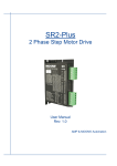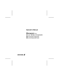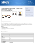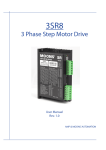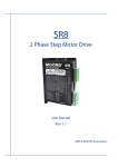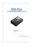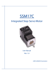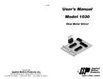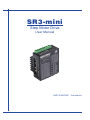
1
SR3-mini
Step Motor Drive
User Manual
AMP & MOONS’ Automation
SR3-mini User Manual
Contents
1 Introduction................................................................................... 3
1.1 Overview.............................................................................................3
1.2 Features..............................................................................................3
1.3 Block Diagram....................................................................................4
1.4 Safety Instructions..............................................................................5
2 Getting Started............................................................................. 6
2.1 Mounting Hardware............................................................................6
2.2 Choosing a Power Supply..................................................................7
2.2.1 Voltage Selection..........................................................................................7
2.2.2 Current.........................................................................................................9
3 Connections............................................................................... 12
3.1 Connecting the Power Supply..........................................................12
3.2 Connecting the Inputs & Outputs......................................................13
3.2.1 Connector Pin Diagram..............................................................................13
3.2.2 STEP & DIR Inputs.....................................................................................13
3.2.3 EN Input.....................................................................................................14
4 Switch Selecting......................................................................... 15
4.1 Running Current...............................................................................15
4.3 Microstep Setting..............................................................................16
4.4 Self Test ..........................................................................................17
4.5 Step Smoothing Filter........................................................................17
4.6 Control Mode.....................................................................................17
4.7 Noise Filter........................................................................................17
4.8 Motor Selction....................................................................................18
5 Troubleshooting.......................................................................... 19
6 Reference Materials................................................................... 20
6.1 Mechanical Outline...........................................................................20
6.2 Technical Specifications....................................................................21
6.3 Torque Curves..................................................................................22
6.4 Drive/Motor Heating..........................................................................23
7 Contacting MOONS’................................................................... 24
Rev. 1.0
3/22/2013
2
SR3-mini User Manual
1 Introduction
Thank you for selecting the MOONS’ SR3-mini step motor drive. We hope our commitment to
performance, quality and economy will make a successful motion control project.
1.1 Overview
The SR3-mini Step motor drive is a cost-effective, high performance drive. The design is based on
advanced digital current control technology, and features high torque, low noise and low vibration.
Running current, microstep resolution, and other parameters are switch selectable so software
configuration is not required.
1.2 Features
• Power Supply - Operates from a 12 to 48 volt DC power supply
• Inputs - 3 optically isolated digital inputs, 5 to 24 volts
• Speed Range - up to 3000 rpm
• Current Control - 3 piano switch setting running current, 3 amps peak maximum
• Idle Current - Switch selectable for reduction to 50% or 90% of running current 1 second after
the motor stops
• Self Test - Performs a 2 rev, 1 rps, CW/CCW move test, switch selectable: ON or OFF
• Control Mode - Step & Direction mode, CW/CCW mode
• Microstep Resolution - 4 piano Switch selectable, 16 settings: 200, 400, 800, 1600, 3200,
6400,12800, 25600, 1000, 2000, 4000, 5000, 6000, 8000, 10000, 20000 steps/rev
3
Rev. 1.0
3/22/2013
SR3-mini User Manual
1.3 Block Diagram
SR3-mini
Block Diagram
Input Filter
Control Mode
Smoothing Filter
Self Test
STEP+
STEPDIR+
DIREN+
EN-
I/O Connector
12-48 VDC
External
Power Supply
Power
Connector
Step Res 4
Step Res 3
Step Res 2
Step Res 1
Idel Current
Current Level 3
Current Level 2
Current Level 1
3.3VDC
Internal
Logic
Supply
Voltage
Temp
Det.
GND
MOSFET
PWM
Power
Amplifier
+12 to 48VDC
Optical
Iso
Digital
Filter
Software
Filter
Optical
Iso
Digital
Filter
Software
Filter
Optical
Iso
Digital
Filter
Software
Filter
I/O Configurations
STEP(5-24V)
: Step Input
: CW
Rev. 1.0
3/22/2013
DIR(5-24V)
: Direction Input
: CCW
4
EN(5-24V)
: Enable Input
: Alarm Reset
DSP
Driver
Controller
Over
Current
Det.
Status
motor
SR3-mini User Manual
1.4 Safety Instructions
Only qualified personnel should transport, assemble, install, operate, or maintain this equipment.
Properly qualified personnel are persons who are familiar with the transport, assembly, installation,
operation, and maintenance of motors, and who meet the appropriate qualifications for their jobs.
To minimize the risk of potential safety problems, all applicable local and national codes regulating
the installation and operation of equipment should be followed. These codes may vary from area
to area and it is the responsibility of the operating personnel to determine which codes should be
followed, and to verify that the equipment, installation, and operation are in compliance with the
latest revision of these codes.
Equipment damage or serious injury to personnel can result from the failure to follow all applicable
codes and standards. MOONS’ does not guarantee the products described in this publication
are suitable for a particular application, nor do they assume any responsibility for product design,
installation, or operation.
• Read all available documentation before assembly and operation. Incorrect handling of the
products referenced in this manual can result in injury and damage to persons and machinery. All
technical information concerning the installation requirements must be strictly adhered to.
• It is vital to ensure that all system components are connected to earth ground. Electrical safety
is impossible without a low-resistance earth connection.
• This product contains electrostatically sensitive components that can be damaged by incorrect
handling. Follow qualified anti-static procedures before touching the product.
• During operation keep all covers and cabinet doors shut to avoid any hazards that could
possibly cause severe damage to the product or personal health.
• During operation the product may have components that are live or have hot surfaces.
• Never plug in or unplug the step motor drive while the system is live. The possibility of electric
arcing can cause damage.
Be alert to the potential for personal injury. Follow all recommended precautions and safe
operating practices. Safety notices in this manual provide important information. Read and
be familiar with these instructions before attempting installation, operation, or maintenance.
The purpose of this section is to alert users to the possible safety hazards associated with this
equipment and the precautions necessary to reduce the risk of personal injury and damage to
equipment. Failure to observe these precautions could result in serious bodily injury, damage to
the equipment, or operational difficulty.
5
Rev. 1.0
3/22/2013
SR3-mini User Manual
2 Getting Started
To use the SR3-mini step motor drive, the following items are needed:
• A 12 - 48 volt DC power supply, see the section below entitled “Choosing a Power Supply” for
help in choosing the right one
• Step & Direction signals
• A small flat blade screwdriver for configuring the switches (included)
2.1 Mounting Hardware
As with any step motor, the SR3-mini must be mounted so as to provide maximum heat sinking
and airflow. Keep enough space around the Step motor drive to allow for airflow.
Rev. 1.0
3/22/2013
•
Never use the drive where there is no airflow or where other devices cause the surrounding air to be more than 40°C (104°F).
•
Never put the drive where it can get wet.
•
Never use the drive where metal or other electrically conductive particles can infiltrate the drive.
•
Always provide airflow around the drive.
6
SR3-mini User Manual
2.2 Choosing a Power Supply
The main considerations when choosing a power supply are the voltage and current requirements
for the application.
2.2.1 Voltage Selection
The SR3-mini is designed to give optimum performance between 12 and 48 volts DC. Choosing
the voltage depends on the performance needed and motor/drive heating that is acceptable and/
or does not cause a drive over-temperature. Higher voltages will give higher speed performance
but will cause the SR3-mini to produce higher temperatures. Using power supplies with voltage
outputs that are near the drive maximum may significantly reduce the operational duty-cycle.
The extended range of operation can be as low as 10 VDC minimum to as high as 53 VDC
maximum. When operating below 12 VDC, the power supply input may require larger capacitance
to prevent under-voltage and internal-supply alarms. Current spikes may make supply readings
erratic. The supply input cannot go below 12 VDC for reliable operation. Absolute minimum power
supply input is 10 VDC. If the Input supply drops below 10 VDC the low voltage alarm will be
triggered. This will not fault the drive.
Absolute maximum power supply input is 53 VDC at which point an over-voltage alarm and fault
will occur. When using a power supply that is regulated and is near the drive maximum voltage
of 53 VDC, a voltage clamp may be required to prevent over-voltage when regeneration occurs.
The RC880 Regeneration Clamp is recommended for the SR3-mini in this situation (see 3.1
“Connecting the Power Supply” below). When using an unregulated power supply, make sure the
no-load voltage of the supply does not exceed the drive’s maximum input voltage of 53 VDC.
The charts below show the heat output, in watts, of the drive at various speeds and voltages. See
section 6.4 on Drive/Motor Heating for more information.
SR3-mini Motor 17HD6426-06N Wattage VS Speed
1.65 amps @ ambient of 40°C
60x65x6(mm) Aluminum Plate
60
12V Watts
24V Watts
48V Watts
Power Supply (Watts)
50
40
30
20
10
0
0
10
20
30
Speed (RPS)
7
40
50
Rev. 1.0
3/22/2013
SR3-mini User Manual
SR3-mini Motor 23HS2449-01 Wattage VS Speed
2.25 amps @ ambient of 40°C
200x200x5(mm) Aluminum Plate
60
12V Watts
24V Watts
48V Watts
Power Supply (Watts)
50
40
30
20
10
0
0
10
20
30
Speed (RPS)
Rev. 1.0
3/22/2013
8
40
50
SR3-mini User Manual
2.2.2 Current
The maximum supply currents required by the SR3-mini are shown in the charts below at different
power supply voltage inputs. The SR3-mini power supply current is lower than the winding
currents because it uses switching amplifiers to convert a high voltage and low current into lower
voltage and higher current. The more the power supply voltage exceeds the motor voltage, the
less current will be required from the power supply.
It is important to note that the current draw is significantly different at higher speeds depending
on the torque load to the motor. Estimating how much current is necessary may require a good
analysis of the load the motor will encounter.
SR3-mini Motor 17HD6426-06N Power Supply Current
(Supply Voltage 12V, Drive Current1.65A)
0.6
1.4
1.2
1
0.4
0.8
0.3
0.6
0.2
Supply Current
(Full Load)
Supply Current
(No Load)
0.4
0.1
0
Torque Current
Amps
Torque(N.m)
0.5
0.2
0
10
20
30
40
50
0
Speed(RPS)
0.6
1.4
0.5
1.2
0.4
1
0.3
0.8
0.2
0.6
0.1
0.4
6E-16
-0.1
Amps
Torque(N.m)
SR3-mini Motor 17HD6426-06N Power Supply Current
(Supply Voltage 24V, Drive Current1.65A)
0
10
20
30
40
50
Torque Current
Supply Current
(Full Load)
Supply Current
(No Load)
0.2
0
Speed(RPS)
9
Rev. 1.0
3/22/2013
SR3-mini User Manual
SR3-mini Motor 17HD6426-06N Power Supply Current
(Supply Voltage 48V, Drive Current1.65A)
0.6
1.2
1
0.4
Torque Curves
0.8
0.3
0.6
0.2
Amps
Torque(N.m)
0.5
0.4
0.1
0
1.4
Supply Current
(Full Load)
Supply Current
(No Load)
0.2
0
10
20
30
40
50
0
Speed(RPS)
1.2
SR3-mini Motor 23HS2449-01 Power Supply Current
(Supply Voltage 12V, Drive Current 2.25A)
0.8
Amps
Torque(N.m)
1
0.6
0.4
0.2
0
1.8
1.6
1.4
1.2
1
0.8
0.6
0.4
0.2
0
0
10
20
30
Torque Curves
Supply Current
(Full Load)
Supply Current
(No Load)
Speed(RPS)
SR3-mini Motor 23HS2449-01 Power Supply Current
(Supply Voltage 24V, Drive Current 2.25A)
1.2
1.2
1
0.8
0.8
0.6
0.6
0.4
0.4
0.2
0.2
0
10
20
30
40
Speed(RPS)
Rev. 1.0
3/22/2013
10
50
0
Torque Curves
Amps
Torque(N.m)
1
0
1.4
Supply Current
(Full Load)
Supply Current
(No Load)
SR3-mini User Manual
1.4
1.2
Torque(N.m)
1
1
0.8
0.8
0.6
0.6
0.4
0.4
0.2
0
Torque Curves
Amps
1.2
SR3-mini Motor 23HS2449-01 Power Supply Current
(Supply Voltage 48V, Drive Current 2.25A)
Supply Current
(Full Load)
Supply Current
(No Load)
0.2
0
10
20
30
40
50
0
Speed(RPS)
11
Rev. 1.0
3/22/2013
SR3-mini User Manual
3 Connections
3.1 Connecting the Power Supply
If the power supply does not have a fuse on the output or some kind of short circuit current limiting
device a fast acting fuse is required. A 3 amp fast acting fuse should be installed in line with the
“+” power supply lead.
Connect the power supply “+” terminal to the drive “ V+” terminal. Connect the power supply “-”
terminal to the drive “ V-” terminal.
Be careful not to reverse the wires. Reversing the connection may open the internal fuse
and void the warranty.
If a regulated power supply is being used, there may be a problem with regeneration. When a
load decelerates rapidly from a high speed, some of the kinetic energy of the load is transferred
back to the power supply, possibly tripping the over-voltage protection of a regulated power
supply, causing it to shut down. This problem can be solved with the use of a MOONS’ RC880
Regeneration Clamp. It is recommended that an RC880 initially be installed in an application. If
the “regen” LED on the RC880 never flashes, the clamp is not necessary.
LEDs
Green- Power
Red - Regen
RC880 Regen Clamp
Rev. 1.0
3/22/2013
12
SR3-mini User Manual
3.2 Connecting the Inputs & Outputs
3.2.1 Connector Pin Diagram
V-
Power
V+
STEP+
STEPDIR+
DIREN+
EN-
Inputs
3.2.2 STEP & DIR Inputs
The SR3-mini step motor drive has two high speed optically isolated inputs called STEP and DIR.
They accept 5 to 24 volt single-ended or differential signals, up to 500KHz. The maximum voltage
that can be applied to the input is 28V.
The motor executes one step when the STEP input closes.
The direction of rotation is controlled by the DIR input state. A closed input (logic “0”) will result in
clockwise rotation, and an open input (logic “1”) will result in counterclockwise rotation.
DIR+
+5v to +24v out
Indexer
with
Sinking
Outputs
DIR
DIRSTEP+
STEP
SR3-mini
STEP-
Connecting to Indexer with Sinking Outputs
Indexer
with
Sourcing
Outputs
DIR
DIR+
COM
DIR-
STEP
STEP+
SR3-mini
STEP-
Connecting to Indexer with Sourcing Outputs
Indexer
with
Differential
Outputs
DIR+
DIR+
DIR-
DIR-
STEP+
STEP+
STEP-
STEP-
SR3-mini
Connecting to Indexer with Differential Outputs
Many high-speed indexers have differential outputs
13
Rev. 1.0
3/22/2013
SR3-mini User Manual
3.2.3 EN Input
The EN input enables or disables the drive amplifier. It is an optically isolated input that accepts
a 5 to 24 volt single-ended or differential signal. The maximum voltage that can be applied to the
input is 28V.
When EN input is closed, the drive amplifier is deactivated. All the MOSFETs will shutdown, and
the motor is free. When EN input is open, the drive is activated.
When the drive has encountered an error and the fault is removed from system, a falling signal
into the EN input will reset the error status and activate the drive amplifier again.
5~24V
Power
Supply
+
EN+
Switch or Relay
(closed = logic low)
-
SR3-mini
EN-
Connecting the Input to a Switch or Relay
+
5~24V
Power
Supply
-
EN+
+
NPN
Proximity
Sensor
−
SR3-mini
output
EN-
Connecting an NPN type Proximity Sensor to an input
(when prox sensor activates, input goes low)
+
5~24V
Power
Supply
output
+
PNP
Proximity
Sensor
-
-
EN+
SR3-mini
EN-
Connecting an PNP type Proximity Sensor to an input
(when prox sensor activates, input goes low)
Rev. 1.0
3/22/2013
14
SR3-mini User Manual
4 Switch Selecting
LED
SW1
SW2
SW1-8 SW9-12
SW3
SW4
Running Current
SW5
SW6
Idle Current
SW9
SW10
SW7
SW8
Microstep
SW11
SW12
Control Mode
Self Test
Step Smoothing Filter
Step Noise Filter
4.1 Running Current
The output current of the SR3-mini step motor drive is set by the SW1, SW2 and SW3 switches
and can be changed as necessary. There are 4 settings available according to the ON/OFF
combination of the switches.
Current
(Amps)
SW1
SW2
SW3
0.4
ON
ON
ON
0.8
OFF
ON
ON
1.2
ON
OFF
ON
1.6
OFF
OFF
ON
2.0
ON
ON
OFF
2.4
OFF
ON
OFF
2.7
ON
OFF
OFF
3.0
OFF
OFF
OFF
Current Setting
1 2 3
SW1
SW2
SW3
1 2 3
1 2 3
1 2 3
1 2 3
1 2 3
1 2 3
1 2 3
1 2 3
2.0
2.4
2.7
3.0
0.4
0.8
15
1.2
1.6
Rev. 1.0
3/22/2013
SR3-mini User Manual
4.2 Idle Current
The running current of the SR3-mini is automatically reduced whenever
the motor isn’t moving. Setting the SW4 switch to ON maintains 50% of the
running current. Setting this switch to OFF maintains 90% of the running
current. This 90% setting is useful when a high holding torque is required.
To minimize motor and drive heating it is highly recommended that the idle
current reduction feature be set to 50% unless the application requires the
higher setting.
4
ON
OFF
90%
50%
Idle Current
4.3 Microstep Setting
SR3-mini setting switch SW5, SW6, SW7, SW8. There are 16 settings.
Steps/Rev
SW5
SW6
SW7
SW8
200
ON
ON
ON
ON
400
OFF
ON
ON
ON
800
ON
OFF
ON
ON
1600
OFF
OFF
ON
ON
3200
ON
ON
OFF
ON
6400
OFF
ON
OFF
ON
12800
ON
OFF
OFF
ON
25600
OFF
OFF
OFF
ON
1000
ON
ON
ON
OFF
2000
OFF
ON
ON
OFF
4000
ON
OFF
ON
OFF
5000
OFF
OFF
ON
OFF
6000
ON
ON
OFF
OFF
8000
OFF
ON
OFF
OFF
10000
ON
OFF
OFF
OFF
20000
OFF
OFF
OFF
OFF
Micorstep
5 6 7 8
SW5
SW6
SW7
SW8
5 6 7 8
5 6 7 8
5 6 7 8
5 6 7 8
5 6 7 8
5 6 7 8
5 6 7 8
5 6 7 8
5 6 7 8
5 6 7 8
5 6 7 8
5 6 7 8
5 6 7 8
5 6 7 8
5 6 7 8
5 6 7 8
200
3200
1000
6000
Rev. 1.0
3/22/2013
400
6400
2000
8000
16
800
12800
4000
10000
4
1600
25600
5000
20000
SR3-mini User Manual
4.4 Self Test
A built-in self-test feature is available on the SR3-mini to check the
physical operation of the motor. Setting switch SW9 to ON after the
drive is powered up will cause the drive to perform a self test move of
2 revolutions both CW and CCW at 1rps. Setting switch SW9 to OFF
disables this feature.
9
9
OFF
ON
SELF TEST
4.5 Step Smoothing Filter
Command signal smoothing can soften the effect of immediate changes in velocity and direction,
making the motion of the motor less jerky. An added advantage is that it can reduce the wear on
mechanical components. SW10 selects this function - ON enables it, OFF disables it.
This function can cause a small delay in following the control signal, and it should be used with
that in mind.
10
10
ON
OFF
4.6 Control Mode
Switch SW11 sets control mode . Switch OFF sets the Step & Dir mode. Switch ON sets the CW/
CCW mode.
4.7 Step Noise Filter
Switch SW12 sets the digital signal filter. The STEP and DIR signal inputs have built-in digital
filters and this setting will reduce external noise. If the system works on the low microstep, select
the 150 KHz (ON) setting. If the system works on the high microstep, select the 500KHz (OFF)
setting.
12
12
ON
150 KHz
17
OFF
500KHz
Rev. 1.0
3/22/2013
SR3-mini User Manual
4.8 Motor Selction
Motor wires setting:
GND
B- B+ A- A+
4 LEAD BIPOLAR DRIVE
Black A+
4 LEAD
Motor
Green A-
Red B+
Blue B-
Rev. 1.0
3/22/2013
18
SR3-mini User Manual
5 Troubleshooting
LED Error Codes
The SR3-mini has one bicolor (red/green) LED to indicate status and errors. When the motor is
enabled, the LED slowly flashes green. When the LED is solid green, the motor is disabled. If the
LED flashes red, an error has occurred. Errors are indicated by a combination of red and green
flashes as follows:
Code
Error
Solid
Motor Disabled
Flashing
Motor Enabled
3 red, 1 green
Over Temperature
3 red, 2 green
Bad Internal Voltage
4 red, 1 green
Power Supply Over Voltage
4 red, 2 green
Power Supply Under Voltage
5 red, 1 green
Over Current/Short Circuit
6 red, 1 green
Open Widing
19
Rev. 1.0
3/22/2013
SR3-mini User Manual
6 Reference Materials
6.1 Mechanical Outline
GND
28
23
18
11
6
6
46
34
63
44
38
Ø5
5
2-Ø3.5
Rev. 1.0
3/22/2013
20
SR3-mini User Manual
6.2 Technical Specifications
Power Amplifier
Amplifier Type
Dual H-Bridge, 4 Quadrant
Current Control
4 state PWM at 16 KHz
Power Supply
External 12 - 48 volt power supply required
Input Voltage Range
10 - 53 volts min/max (nominal 12 - 48 volts), voltages outside this range will
cause driver faults and/or may damage the drive
Protection
Over-voltage, over-current, under-voltage, over-temp, internal motor shorts
(phase-to-phase, phase-to-ground)
Ambient Temperature 0 - 40°C (32 - 104°F) when mounted to a suitable heatsink
Humidity
90% non-condensing
Controller
Current Control
Advanced digital current control provides excellent high speed torque
Speed Range
Speeds up to 3000 rpm
Auto Setup
Measures motor parameters to configure current control and anti-resonance gain
settings
Step Input
STEP+/-
Inputs: optically isolated, 5 - 24 volts, min. pulse width 250 us., max. pulse
frequency 500KHz; motor executes one step when the STEP input closes
Direction Input
DIR+/-
Inputs: optically isolated, 5 - 24 volts, min. pulse width 62.5 us., max. pulse
frequency 500KHz; direction of rotation is controlled by the DIR input state
Enable Input
EN+/-
Inputs: optically isolated, 5 - 24 volts, min. pulse width 500 us., max. pulse
frequency 10 KHz; enables or disables the drive amplifier
Running Current
Switch selectable, 8 settings: 3 amps peak maximum
Idle Current
Reduction
Automatically reduces the current 1 second after the motor stops; switch
selectable, 2 settings: 50% or 90% of the running current
Microstep Resolution
Switch selectable, 16 settings: 200, 400, 800, 1600, 3200, 6400, 12800, 25600
1000, 2000, 4000, 5000, 6000, 8000, 10000, 20000 steps/rev
Self Test
Checks internal and external power supply voltages, 2 rev move both CW and
CCW at 1rps, switch selectable, ON or OFF
Modes Of Control
Step & Direction,CW/CCW
21
Rev. 1.0
3/22/2013
SR3-mini User Manual
6.3 Torque Curves
17HD6426-06N
Drive: SR3-mini
Microstep: 20000 step/rev
Current: 1.65A (Peak)
0.5
12V
24V
48V
Torque(N.m)
0.4
0.3
0.2
0.1
0
0
10
20
23HS2449-01
Drive: SR3-mini
Microstep: 20000 step/rev
Current: 2.25A (Peak)
Speed(rps)
12V
30
24V
40
50
40
50
48V
1.2
Torque(N.m)
1
0.8
0.6
0.4
0.2
0
0
10
20
Speed(rps)
30
Note: all torque curves were measured at 20,000 steps/rev.
Rev. 1.0
3/22/2013
22
SR3-mini User Manual
6.4 Drive/Motor Heating
Step motors convert electrical power from the driver into mechanical power to move a load.
Because step motors are not 100% efficient, some of the electrical power turns into heat as it
passes through the motor. The amount of heating is not so much dependent on the load being
driven as on the motor speed and power supply voltage. There are certain combinations of speed
and voltage at which a motor cannot be continuously operated without damage occurring to the
motor.
A step motor typically reaches its maximum temperature after 30 to 45 minutes of operation. A
motor that runs for one minute and then rests for one minute is said to have a duty cycle of 50%.
Five minutes of running and five minutes of rest is also a 50% duty cycle. However, one hour of
running and one hour of rest has the effect of 100% duty cycle as the motor will reach full and
possible excessive temperature during the first hour. The actual temperature of the motor depends
on how much heat is conducted, convected or radiated out of it.
The curves below result from measurements made in a 40°C (104°F) environment with the motor
mounted to an aluminum plate sized to provide a surface area consistent with the motor power
dissipation. Results may vary.
SR3-mini Motor 17HD6426-06N Wattage VS Speed
1.65 amps @ ambient of 40°C
60x65x6(mm) Aluminum Plate
12V Watts
24V Watts
48V Watts
60
Power Supply (Watts)
50
40
30
20
10
0
0
10
20
30
40
50
Speed (RPS)
SR3-mini Motor 23HS2449-01 Wattage VS Speed
2.25 amps @ ambient of 40°C
200x200x5(mm) Aluminum Plate
12V Watts
24V Watts
48V Watts
60
Power Supply (Watts)
50
40
30
20
10
0
0
10
20
30
40
50
Speed (RPS)
23
Rev. 1.0
3/22/2013
SR3-mini User Manual
7 Contacting MOONS’
Service Center
+86-400-820-9661
■ Headquarters
No. 168 Mingjia Road Industrial Park North Minhang District Shanghai 201107, P.R. China
Tel: +86(0)21-52634688
Fax: +86(0)21-62968682
E-mail: [email protected]
■ MOONS' Industries (America), Inc.
1113 North Prospect Avenue,Itasca, IL 60143 U.S.A.
Tel: 001-630-833-5940
Fax: 001-630-833-5946
■ MOONS' Industries (Europe) S.r.l.
Via Torri Bianche n.1 20059 Vimercate(MB) Italy
Tel: +39 039 62 60 521
Fax: +39 039 96 31 409
■ MOONS' Industries (South-East Asia) Pte Ltd.
33 Ubi Avenue 3 #08-23 Vertex Singapore 408868
Tel: +65 6634 1198
Fax: +65 6634 1138
■ Shenzhen Branch Office
Room 2209, 22/F, Kerry Center,No. 2008 Renminnan Road Shenzhen 518001 P. R.China
Tel: +86 (0)755 25472080
Fax: +86 (0)755 25472081
■ Beijing Branch Office
Room 202, Unit 2, 7th Building,Huilongsen International Science & Technology Industry Park,
No.99, Kechuang 14th Street,Beijing 101111 P. R.China
Tel: +86 (0)10 59755578
Fax: +86 (0)10 59755579
■ Qingdao Branch Office
Room 10E, No.73 Wangjiao Mansion, mid. Hongkong Road Qingdao 266071 P. R.China
Tel: +86 (0)532 85879625
Fax: +86 (0)532 85879512
■ Wuhan Branch Office
Room 3001, World Trade Tower, No.686 Jiefang Avenue, Jianghan District, Wuhan 430022 P.R.China
Tel: +86 (0)27-85448742
Fax: +86 (0)27-85448355
■ Nanjing Branch Office
Room 302, Building A, Tengfei Creation Center,55 Jiangjun Avenue, Jiangning District,Nanjing 211100 P. R.China
Tel: +86 (0)25 52785841
Fax: +86 (0)25 52785485
■ Chengdu Branch Office
Room 1917, Western Tower, No.19,4th Section of South People Road,Wuhou District,Chengdu 610041
P.R.China
Tel: +86 (0)28-85268102
Fax: +86 (0)28-85268103
Rev. 1.0
3/22/2013
24