1
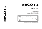
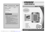
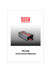
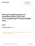
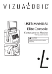
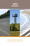
TS-700/1000 Inverter Instruction Manual TS-700/1000 Inverter Instruction Manual Index 1. Safety Guidelines ............................................................................... 1 2. Introduction ........................................................................................ 1 2.1 Features ......................................................................................... 1 2.2 M ain Spe cific atio n ........................................................................ 2 3. User Interface ...................................................................................... 2 3.1 Front Panel .................................................................................... 2 3 .2 L ED Indicato r on Fro nt P ane l ...................................................... 3 .3 R ear Pan el .................................................................................... 4. Setup (Out put Voltage, Frequency, and Saving Mode)..................... 4 .1 Initia l State .................................................................................. 3 5 .2 O utp ut P rote ctio n ........................................................................ 6. Ins tall ation & Wiring .......................................................................... 7. Failure Correction Not es ................................................................... 8. Warran ty ............................................................................................. 6 3 4 4 4 .2 P roc edu re o f Setting Up Out put Voltage , Fre que ncy, and Saving Mode ................................................................................. 4 5. Pro tection ........................................................................................... 6 5 .1 Input Pro tec tion ........................................................................... 6 7 10 10 Apr. 2014 Version 7 1.Sa fety Guidelines (Please rea d through this manual before assem bling TS700/1000) ‧Risk of electrical shock and energy hazard. All failu res sho uld be examined by the qual ified technician. Ple ase do not remo ve the case of the inve rter by yourself! ‧Plea se d o no t install the inverter in places with hig h moisture o r nea r wa ter. ‧Please do not install the inverter in places with high ambient temperature, under direct sunlight or nea r flam e source. ‧Plea se o nly connect batteries with the sam e b rand and mo del numb er in one battery bank. Using batteries from different manufacturers or different capacity is strictly prohibited! ‧Nev e r a llow a sp ark or flame in t he v icin ity o f th e ba tteries b eca use it m ay generate explosive gases during n ormal operation. ‧Make sure th e air flo w fro m the fan is not obstruc ted at both s ides (fro nt a nd back) of the inverter. Please allow at least 15cm o f space. ‧Plea se d o no t stack any object on the inverter. WARNING: Batteries will have aging problem after years of operation. It is suggeste d to exe cute re g ul ar battery maintena nce (e.g. every year). Once aged, the batteries should be changed by professional technician, or the failed batteries may cause fire or other hazards. Inverter Inverter Don't disasse mble Away fro m moistu re Inverter Away from fir e or h igh temperature Don't stack on the inverter Inve rter K eep good ve ntilation WARNING : Th is is a class A product. In a domestic environment this produc t may cause radio interference in which case the user may be required to take adequate measures. 2. Introduction ‧Fully digital controlled by an advanced CPU, TS-700/1000 is a true sine wave D C/AC In verter, Draw ing pow er from battery bank an d co nve rting it into AC voltage. ‧With pure sine wave output, TS -1000 can provi de 1 000W contin uously, 1150 W fo r 3 minutes, and surge power 2000W. (TS -700 can provide 700W continously, 800W for 3 minutes, and surge power 1400W.) G eneral applications include PC, IT E, vehicles, yachts, home ap pliances, motors, power tools, indust rial control equipmen ts, AV systemsand etc... 2.1 Features ‧True sine wave output (THD < 3.0% ) ‧700W / 1000W rated output ‧High efficiency up to 92% ‧Co mplete LED indi catio n for operation status ‧Battery low alarm and indicator ‧Ou tput vol tage / Frequency selectable 1 ‧Fully digital controlled including monitoring & display ‧Compliance to UL 4 58(only TS- 1000) / F CC / E 13 / CE ‧Can be used for m ost electronic products w ith AC input ‧3 years globa l warranty 2.2 Mai n Sp ecification TS -700 Model Rated O power U T AC voltage P U T Waveform Protection 112 124 148 212 224 248 700W max. continuously, 800W max. for 180 seconds, 1050W max. for 10 seconds 1 400W (30cy cles) True sine wave (THD <3.0 %) at rated input voltage AC sho rt、Ov erload 、Ove r Temperatu re Ba t. voltage 10.5 ~ 15.0V 21.0 ~ 30.0V 42.0 ~ 60.0V 10.5 ~ 15.0V 21.0 ~ 30.0V 42.0 ~ 60.0V range I 38A 19A N DC curre nt 7 5A P Efficiency 8 6% 88% 89% U Off mode T Under 1.0mA at power sw itch OFF current d raw Pr otection 75A 89% 38A 90% 19A 91% Over current、battery polarity reverse by fuse、battery low shutdown、battery low alarm TS -1000 Model Rated power O U T AC voltage P U T Waveform Protection 112 124 148 212 224 248 1000W max. continuously, 1150W max. for 180 seconds, 1500W max. for 10 seconds 2 000W (30cy cles) True sine wave (THD <3.0 %) at rated input voltage AC sho rt、Ov erload 、Ove r Temperatu re Ba t. voltage 10.5 ~ 15.0V 21.0 ~ 30.0V 42.0 ~ 60.0V 10.5 ~ 15.0V 21.0 ~ 30.0V 42.0 ~ 60.0V range I 50A 25A N DC curre nt 1 00A P Efficiency 8 8% 89% 90% U Off mode T Under 1.0mA at power sw itch OFF current d raw Pr otection 100A 90% 50A 91% 25A 92% Over current、battery polarity reverse by fuse、battery low shutdown、battery low alarm 3.Use r Interface 3.1 Fro nt Panel A POWER ON/OFF switch: The inverter will turn OFF if the switch is in the O FF position. B AC output outlet: For application demands of different geographic areas all over the world, there are many different kinds of optional AC outlets to choose from. 2 C Ventilation holes: The inverter requires suitable ventilation to work properly. Please make sure there is good ventilation and the lifespan of the inverter can be preserved. D Fu nction Setting: Output volta ge, frequency, a nd s avin g m ode can be set through this button. E LED Indicating Panel: Ope rating status, battery status, load condition, and all kind s of warnings will be disp layed on this panel. B C AC Output D Setting ON A Status OFF Battery Load } E Remote port Figure 3.1: Fro nt P anel 3 .2 LED Indicato r on Front Panel Status LED: Represents current operating status LED color Status Green Orange Red Normal Saving m ode Abnormal *Note: Refer to section 5.2 for e xpla natio n o f abnormal status Ba ttery LED :Represents th e remaining capacity of external batteries LED color Battery capacity Green Orange Red >70% 40 ~ 70% <40% LO AD L ED :Represents the magnitude of output load LED color Load perce ntage Green <50% Orange Red 50 ~ 80% >80% 3.3 Rear Panel B A Battery input (+),(-) B Fan ventilation opening Reve rse P ola rit y Wi ll Damage T he Uni t. WARNING: C Frame ground (FG) I nver ter Inver te r NE G B ATT ERY P OS I nv ert er Inverte r A Cat .N o.(1G G 1H S- 212) Wi re Ran ge(1 0-4 A WG S tr Cu S ol de re d W ir es ) Torqu e ( 17.7-26 . 5 in lb ) Ch ass is G rou nd C Fig 3.2: Rear Panel 3 4.Se tup (Output Voltage, Frequency, and Saving Mode) 4.1 Initial State The initial state is set to110Vac/60Hz or 230Vac/50H z and disabled "Saving Mode" is a ctiva ted . If u ser s ne ed to revise it fo r ce rtain app lica tion , it c an be don e th e se tting but ton on the front panel (P leas e re fer to sectio n 4.2). Th e un it w ill st art u p a utom atic ally afte r th e se tting pro ced ure is finish ed and the new settings will be executed. These new setting s w ill be kept even if the unit is power off/on fo r any re ason. 4.2 Procedure of Setting up Output Voltage, Frequency, and S aving M ode ST EP 1: Th e in verter s hou ld b e turn ed off w hil e re s etti ng. Inpu t ba tteri es should be connected and the loads should be re moved. STEP 2 : Us e an ins ulated s tick to p ress the setting button and th en turn on th e power swi tch. O range led indication will flash ON an d OFF. after pressing for 5 secon ds, the inve rter will send out a "Beep" s oun d. U se rs ca n re le a se the b utto n and g o i nto t he se tti ng procedure. STEP 3: Pleas e refer to Ta ble 4-1 and check w hether the com bination of output voltage and fre que ncy is the one you n eed. If yes, please jump to STEP 5. If not, start fro m STEP 4. AC Output Se tting ON St atus OFF Ba t tery Load Use an in sula t ed sti ck to pr ess th i s set ti ng bu tt on Remote port Fig ure 4.1: Adju stment of Output Voltage , Frequency, and Saving Mod e Tab le 4-1: L ED Indication of Output Voltage / Frequency C ombinat ion Output Voltage Frequ ency 1 00Vac (2 00Vac) 11 0Vac (22 0Vac) 115Vac (230Vac) 120Vac ( 240Vac) Status 50Hz Battery Load Status 60Hz Battery Load ● ○ ○ ★ ○ ○ ● ○ ● ★ ○ ● ● ● ○ ★ ● ○ ● ● ● ★ ● ● 4 ● Light ○ Dark ★ Flashing Note : Th e above indi cation will be shown in green STEP 4: The LEDs will change state each tim e you press the setting button for 1 second and the n re lease (refer to F igure 4.2). Please select the suitable comb ination of ou tput voltage and frequency you need. 115Vac (230Vac) 5 0Hz 110Vac (220 Vac) 5 0Hz 1 20Vac (240Vac) 50Hz 100Vac (200 Vac) 50Hz 100Vac (200Vac) 60Hz 120Vac (240 Vac) 6 0Hz 110Vac (220Vac) 60Hz 115Vac (230Vac) 6 0Hz Figu re 4 .2: S tate Circulation Diag ram of O utp ut Voltage and Frequ ency ST EP 5: After selecting the output voltage and frequ ency, press the setting button for 3~5 seconds and the inverter will send out a "Beep" sound. The b utton ca n be released and it goes into the setting section of "Saving Mode". ST EP 6: Please refer to Tab le 4-2 and check whether the "Saving Mode" is already set as you desired . If yes, please jump to S TEP 8. If not, start from STEP 7. Table 4-2 : LED Indication of Saving M ode Selection Sav ing Mod e ON Sav ing Mod e OFF Status ★ Battery ★ Load ● Status ★ Battery ★ Load ○ ● L ight ○ D ark ★ F lashing Note: T he above indication w ill be shown in green STEP 7: The LEDs will change state each time you press the setting button for 1 second and then release. Please activate or cancel the "Saving Mode " function as desired. ST EP 8: After activ ating or canceling the "S aving M ode ", press the setting button for around 5 seconds and the inverter will send out a "Beep" sound. The button can be released and all the settings are finished. T he inverter will auto maticall y store all the settin gs and start to operate. 5 5.Protection 5.1 Input P rotection (A)Battery Polarity Protection: If the b attery input is connected in reverse polarity, the internal fuse of the inverter would blow and the inverter should be send back to MEAN WELL for repair. (B)Battery Under Voltage Protection: When the b attery voltage is low er than the pre set value, th e inverter will au tomatically te rminate the outp ut thus protect the battery from dam age. Please refer to Table 5-1 fo r mo re detail about the failure signals. (C)Battery Over Voltage P rotection: When the battery voltage is too high, inverter will automatically te rminate the output providing and the built-in buz zer will be activated to inform the use rs. P lea se refer to Table 6.1 for more detail about the failure signals. WARNING: Please choose suitable batter ies that is compatible with the rated input D C voltage of TS -700/1000 (refer to the SPE C). If th e input DC voltage is too low (ex. us ing 12V dc battery ban k for 24Vdc input models ), TS -700/10 00 can not be started up properly. If th e input DC voltage is too high (ex. using 48Vdc battery ban k for 24Vdc input models ), TS-70 0/1000 w ill be damaged ! 5.2 Ou tput Protection Th e displa y p anel wil l sh ow f ailu re s tatus w hen inverter is face d w ith abnorm al opera ting conditions (refer to Table 5-1). This lets the user kno w what co uld be the problem. (1)OTP: When the internal tem pera ture is higher than the limit value, the "Over Temperature Protection" will be activated. The unit will automatically turn off and shou ld be restarted a gain. (2)AC output abnormal protection: When the AC output voltage of the inverter is too high o r too low, the unit will turn off and should b e restarted again. (3)AC output short circuit protection: When a short circuit situation occurs at the o utput side of the inverter or the lo ads increase greatly in a short period of tim e, the un it w ill turn off and should be restarted again. (4)Battery voltage abnormal protection: Whe n th e battery voltage is too high or too low, this pro tection w ill be a ctivated. The in verter w ill au to recover after the battery voltage go back to a safe level an d users do not nee d to restart it. (5 ) O L P : Wh e n o ut p ut i s o v e r l o a d ed b e t we e n 73 5 ~ 8 0 0 W ( T S 700 )/10 50~1150 W(T S-1000), the inverte r can still co ntinuously p rovid e pow er fo r 3 minutes. Afte r that, if the overload condition is not rem ove d, overload protection will activate. When the load is higher than 1050W(TS700)/1500W(TS-1000), the o verload protection will be activated instantly. For these overload protections, once activated, the unit must reset to recover. 6 Table 5-1: Failure Messages On Front P ane l ○ S tatu s LED ○ B atte ry Indicator ○ L oad Output ○ ○ Overload ★ (105~115% load) Output ○ Overload ★ (115~150% load) ○ Output ○ Overload ★ (150% load) ★ Fa ilure M essage Abnormal AC Output Voltage ★ ★ ○ AC Output Short Circuit Abnormal Battery Voltage ★ ○ ○ Over Tempe ratu re ○ Status LE D ○ Battery Indicator ○ Load ★ ○ ★ Fa ilure M essage ★ ★ ★ ● Light ○ Dark ★ Flashing LED Status Note: The a bove indication will be shown in red 6.Installation & Wiring (A)Wiring for Batteries: Wire connect ions sho uld be a s short as possible and less than 1.5 meter is highly recommended. Make sure that suitable wires are chosen based on the rating of current. Too small of a cross-section will result in ove rheating that could indu ce certain danger. Please refer to Table 6 -1 and con sult our local distributors if you have any question s. Table 6 -1: S ugg esti on for Wire S election Rated Cu rren t of E quipment (Amp) 16A ~ 25A 25A ~ 32A Cro ss-s ecti on o f Lead (mm 2) 2.5 4 12 10 32A ~ 40A 6 8 40A ~ 63A 10 6 63A ~ 80A 80A ~ 100A 16 4 100A ~ 125A 25 35 2 1 ≧125A 50 0 Model using 48V battery Model using 24V battery Model using 12V battery (B)Suggested battery type and capacity Battery type Ba ttery Capacity Lea d-acid b attery 112 212 124 12V / 120Ah ~ 12V / 400Ah 224 24V / 60Ah ~ 24V / 200Ah 7 148 248 48V / 30Ah ~ 48V / 100A h (C)Requirement of Installation: Th e un it should be mou nted on a flat surface o r holding rack with suitable strengt h. In order to e nsure th e lifespan o f th e unit, p leas e re frain from operating in environment of high dust or high moisture. This is a power supply with built-in DC fan. Please mak e su re that ventilation is not blocked. There sho uld be no barriers within 15cm of the ventilating holes. >15cm Air >15cm Inverter Air Figu re 6.1: E xam ple of In stallation (D)Mounting S ugg estion : Th ere a re 4 sem i-circular cutout on the s ide flanges of the inverter. It can be use d for fixing TS-700/1000 onto the system enclosu re. We hig h recommend mo unting in the ho rizontal position. Please make sure ven tila tion openings are free from obstru ction. (E)Example of system diagram As short as possible Larger than 15cm A C O/P LO AD TS-700/1000 L arger than 1 5cm Battery + - DC I/P -+ Should less than 1.5m Chassis Wall or system FG 8 Where, the DC I/P a nd c hassis fix manner as followin g : 1. Compa ny Na me : Mean Well Enterpris es Co Ltd 2. Model Name : 1GG1HS-1 91 3. Rating : 150A 4. Torque : 106.2 Ib.in max. 5. Suitable Wire : Cop per wire (tem p rati ng : 75 C ) 6. Intended for termin ation o nto a Listed ring to ngue connector 7. To Be Sold Only Wi th Inst allatio n Instr uction s 8. A mounting s crew t hat is f irst ins erted throug h the tang and is th reade d into the connector to secure the connector to t he tang shal l be torqued to 32 i n-lbs minimum 9. Mount ing Screws - Plated Steel . Two p rovided, siz e M8 Cat.No.(1G G1HS-212) Wire Range (10-4 AWG Str Cu Soldered Wires) Torque (17. 7-26.5 in lb) Chas sis (F)Dera ting 100 100 80 80 60 60 40 40 20 20 0 10 20 30 40 50 60 70 10.5VDC 21VDC 42VDC Ambient Temperature (℃) 11.5VDC 23VDC 46VDC 15VDC (HORIZONTAL) 30VDC 60VDC Battery Input Voltage (V) Figure 6.2: Output Derating Curve Figure 6.3: Input Derating Curve (G) Notes on output load: TS-700/1000 Series can power most of equipments that need an AC source which can prov ide 700W(TS-700)/1000 W(T S-1000) continuously. But for certain load type, the u nit may not work properly. 9 (1)Sinc e in ductive loads or motor base d equipm ents ne ed a large s tart up current (6~1 0 times of its ra ted current) , th e inv erte r m ay n ot s tart up succ essfully with these kinds of load. (2)Whe n the output are capacitive or rectified equipm ents (such as sw itching power supply), it is suggested to operate these equipment at no load or light load. To ensure proper operation, you should incre ase the loads on ly after TS-700/1000 has started up. 7. Failure Correction No tes T S-70 0/1000 sho uld be s erviced by a pro fessiona l tec hnician . An y improp er usage or modification may damage the unit or resul t in shock ha zard. If you are not able to clear th e failure condition, please contact Mean WEL L or any of o ur distributors for repair service. Statu s No AC output volta ge Discharging perio d of batte ries is too s hort Fan does not s pin Possible Reasons Ways to Eliminate Abnormal input Check the AC or DC input sources. M ake sure the voltage is within the r equired range. Ov er temperature protection M ake sure that the ventilation is not b locked or wh ether the ambient temperature is too high. Please d erating the o utput usage or reduce the ambient temperature. Ov erload prote ction M ake sure the output load does not e xceed the rated value or the instantaneous start up current is not too high. (for inductive or capacitive loads) Short circuit pr otection M ake sure the output is no t o verloaded or short circui ted Batteries are aged or broken Replace the b atteries Battery capacity is too small Reconfirm the specificatio n and e nlarge the battery capacity as s uggested Clog with foreign bodies Remove the f oreign objects Ma lfunction of the fan Repair requir ed. Please send it back to us or any of our distributors 8. Warranty Three years of global warranty is provided for TS-700/1000 under normal operating conditions. Please do not change components or modify the unit b y yo urs elf or M EAN WELL ma y reserve the right n ot to pr ovide the complete warranty. 10 N o . 2 8 , Wu q u a n 3 r d R d ., Wu g u D i s t . , Ne w Ta i pe i C i t y 2 4 8 , Ta i wa n