1
Appendix D - Digital Interface
13 Appendix D - Digital Interface
If supplied with the option, the 7013 bath is capable of communicating with and being controlled by
other equipment through the digital interface. Two
types of digital interface are available — the RS-232
serial interface and the IEEE-488 GPIB interface.
With a digital interface the bath may be connected
to a computer or other equipment. This allows the user
to set the bath temperature, monitor the temperature,
and access any of the other controller functions, all
using remote communications equipment. In addition
the heater power setting and cooling capacity may be
controlled using the interface. The two baths of the
7013 are connected, set up, and controlled independently. With a few noted exceptions the following
instructions apply to either bath. To allow the functions
to be switched using the interface the “HEATER
POWER” and “BOOST HEATER” switches must be
set to the “OFF” position. The “REFRIGERATION
MODE” and the “COOLING BLOWER” switches must
also be set to “OFF”.
13.1.2
Setup
Before operation the serial interface of the bath
must first be set up by programming the BAUD rate
and other configuration parameters. These parameters are programmed within the serial interface menu.
The serial interface parameters menu is outlined in
Figure 9 on page 30.
To enter the serial parameter programming mode
first press “EXIT” while pressing “SET” and release to
enter the secondary menu. Press “SET” repeatedly
until the display reads “ProbE”. This is the menu
selection. Press “UP” repeatedly until the serial interface menu is indicated with “SErIAL”. Finally press
“SET” to enter the serial parameter menu. In the serial
interface parameters menu are the BAUD rate, the
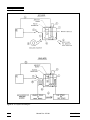
RS-232 Cable Wiring for
IBM PC and Compatibles
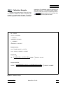
Digital Interface Setup:
HEATER switches - LOW
Instrument
Connector
(DB 9-Pin)
BOOST switch - OFF
BLOWER switch - OFF
REFRIGERATION switch - OFF
13.1
Serial communications
The bath may be installed with an RS-232 serial
interface that allows serial digital communications
over fairly long distances. With the serial interface the
user may access any of the functions, parameters and
settings discussed in Section 7 with the exception of
the BAUD rate setting.
13.1.1
Wiring
The serial communications cable attaches to the
bath through the D-9 connector on the front panel.
Figure 14 shows the pin-out of this connector and
suggested cable wiring.
1
2
3
4
5
6
7
8
9
NC
RxD
TxD
NC
GND
NC
RTS
CTS
NC
Instrument
Connector
(DB 9-Pin)
1
2
3
4
5
6
7
8
9
NC
RxD
TxD
NC
GND
NC
RTS
CTS
NC
Computer (DTE)
Connector
(DB 25-Pin)
2 TxD
3 RxD
4 RTS
5 CTS
6
7 GND
8
20
Computer (DTE)
Connector
(DB 9-Pin)
1
2
3
4
5
6
7
8
9
NC
RxD
TxD
NC
GND
NC
RTS
CTS
NC
Figure 14. Serial Cable Wiring.
50
Manual Rev. 671001
Model 7013