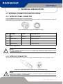
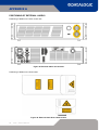
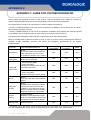
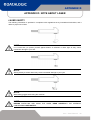
1
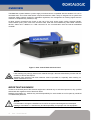
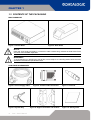
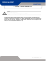
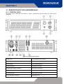
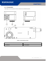
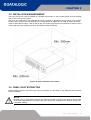
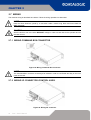
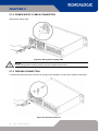
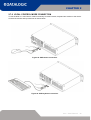
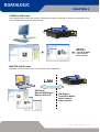
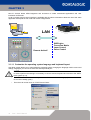
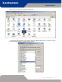
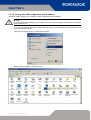
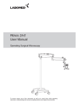
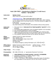
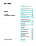
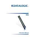
© 2008 – 2014 Datalogic Automation S.r.l. - ALL RIGHTS RESERVED - Protected to
the fullest extent under U.S. and international laws. • Copying, or altering of this
document is prohibited without express written consent from Datalogic Automation
S.r.l.
Datalogic and the Datalogic logo are registered trademarks of Datalogic S.p.A. in
many countries, including the U.S.A. and the E.U.
All other brand and product names mentioned herein are for identification purposes
only and may be trademarks or registered trademarks of their respective owners.
Published 29 January 2014
Printed in Donnas (AO), Italy.
Arex – User’s Manual
ii
SYMBOLS
SYMBOLS
Symbols used in this manual along with their meaning are shown below. Symbols and signs are repeated
within the chapters and/or sections and have the following meaning:
Generic warning:
This symbol indicates the need to read the manual carefully or the necessity of an important
maneuver or maintenance operation.
Electricity Warning:
This symbol indicates dangerous voltage associated with the laser product, or powerful enough to
constitute an electrical risk. This symbol may also appear on the machine at the risk area.
Laser Warning:
This symbol indicates the danger of exposure to visible or invisible laser radiation. This symbol may
also appear on the machine at the risk area.
Fire warning:
This symbol indicates the danger of a fire when processing flammable materials. Because there is a
danger of fire, it is indispensable to follow the instructions provided by the manufacturer when
commissioning the machine.
Note:
Carefully read the user’s manual before using the laser system.
iii
Arex – User’s Manual
REVISION INDEX
REVISION INDEX
Revision
Date
Number of added or
edited pages
821002170
08/05/2012
Release
821002170A
29/01/2014
57
Arex – User’s Manual
iv
FOREWORD
FOREWORD
Information included in this manual are indicated to a qualified installer able to integrate the
equipment into a system, accomplishing with all the protection features required from internationals
rules and local legislations. Please refer to Appendix for further information.
Following manual is referred to an Arex Fiber 1PWX-TLSV system in Class 4 configuration.
In addition to being professionally trained in their role, personnel assigned to work on the machine must be
informed and made acquainted with the risks inherent invisible and visible laser radiation. The operator is
required to carefully read the section of the manual concerning safety instructions as well as the sections
related to matters falling under his responsibility.
The workers assigned to the machine can be identified as:
•
OPERATOR
responsible for loading elements to be processed, visually checking the work cycle, removing the
finished product and cleaning the machine.
•
MAINTENANCE WORKER
responsible for the electrical, mechanical and optical maintenance and adjustment of the machine.
NOTE:
Datalogic Automation S.r.l. declines any and all responsibility for improper use of its device.
NOTE:
BEFORE INSTALLING AND USING THE LASER, READ CAREFULLY THE APPENDICES.
v
Arex – User’s Manual
OVERVIEW
OVERVIEW
The Fiber Laser marking system developed and manufactured by Datalogic Automation employs the most
advanced technologies with regards to the mechanical-optical part, the electronic control of laser beam
power, communication and the overall safety of the entire system.
OPERATION OF A LASER SYSTEM WITH GALVANOMETRIC SCANNING
In pulsed or continuous operation mode, the laser generates an invisible, high-energy infrared beam.
In order to obtain a more accurate focus, the laser beam is first enlarged by using an optical expansion
system and then focused, after being deflected by a scanning system consisting of two mirrors mounted on
galvanometric motors.
These mirrors deflect the beam in a controlled beam along the X and Y axes; etching of the product surface
occurs by coordinating the movement of the two motors with the turning on/off of the laser beam.
The deflected laser beam is focused by an F-Theta lens before it hits the surface of the product.
Generally speaking, the marking is carried out within the focus of the beam.
LASER SOURCE
On AREX system it is used a sealed fiber laser source.
This source is based on the new fiber solid state technology.
It guaranties high stability, lower sensitivity on optical misalignment and a longer product lifetime.
MARKING SOFTWARE
The marking software Lighter is preinstalled on the system.
NOTE:
Consult Lighter software user’s manual for a proper use of the same.
NOTE:
Consult the proper Appendix to upgrade the preinstalled software if necessary.
GALVANOMETRIC SCANNING HEAD
The scanning head features two deflection mirrors that deflect the beam in an X and Y direction, depending
on the graphics to be reproduced.
Arex – User’s Manual
vi
OVERVIEW
The Arex laser system features a power supply unit whose size is compatible with the standard 19” 2,5U in
varnished steel, and a laser head whose compact dimensions make it easy to integrate into a system that
comprises safety systems required by applicable regulations, the management of marking signals and the
customer’s complementary modules, if any.
All laser system connections are found on the rear of the rack: power supply, safety, electrical signals,
communication ports, patch cord to the scannerr head, while the front features key and enable command
devices, status led in addition to a USB connector for the communication with the internal embedded
controller.
Figure 1: Arex Control Rack and Scan Head.
NOTE:
Laser marking may strongly interact with materials through a thermal carbonization process with the
emission of fumes and vapours.
Adequate fume extractor and fume treatment must be provided for, especially when working on
plastic materials such PVC.
IMPORTANT WARNINGS
Access to the internal parts of the electrical equipment is allowed only to authorized personnel, duly qualified
and trained with regards to risks of electrical nature.
Datalogic Automation S.r.l. declines any and all responsibility for work carried out on live parts by untrained
or unauthorized personnel.
NOTE:
It is forbidden to change the intended use for which the system was designed and developed.
Datalogic Automation S.r.l. declines any and all responsibility for improper use of its equipment.
vii
Arex – User’s Manual
SUMMARY
SUMMARY
SYMBOLS
III
REVISION INDEX
IV
FOREWORD
V
OVERVIEW
VI
OPERATION OF A LASER SYSTEM WITH GALVANOMETRIC SCANNING
LASER SOURCE
MARKING SOFTWARE
GALVANOMETRIC SCANNING HEAD
IMPORTANT WARNINGS
vi
vi
vi
vi
vii
SUMMARY
1
VIII
TECHNICAL SPECIFICATIONS AND ACCESSORIES
10
1.1
TECHNICAL CHARACTERISTICS
1.2
SEALS
1.3
CONTENTS OF THE PACKAGING
1.3.1
FOCAL OBJECTIVES (F-Theta)
2
10
12
13
14
INSTALLATION AND SET UP
16
2.1
DESCRIPTION OF THE LASER MODULES
2.1.1
CONTROL RACK
2.1.2
SCAN HEAD
2.2
INSTALLATION PRE-REQUISITES
2.3
AREX TRANSPORT
2.4
FIXING AND POSITIONING
2.5
INSTALLATION ENVIRONMENT
2.6
FUME / DUST EXTRACTOR
2.7
WIRING
2.7.1
WIRING COMMAND BOX CONNECTOR
2.7.2
WIRING I/O CONNECTOR (CONTROL AXES)
2.7.3
INTERLOCK CONNECTOR
2.7.4
POWER SUPPLY CABLE CONNECTION
2.7.5
GROUND CONNECTION
2.7.6
LOCAL CONTROL MODE CONNECTION
2.7.7
REMOTE CONTROL MODE CONNECTION
3
17
17
18
19
19
20
22
22
23
23
23
24
25
25
26
27
FUNCTIONAL SPECIFICATIONS
28
3.1
MANUAL TURNING ON SEQUENCE
3.1.1
ADVICE ON USING THE SYSTEM
28
31
Arex – User’s Manual
viii
SUMMARY
4
TECHNICAL SPECIFICATION
4.1
EXTERNAL CONNECTORS SPECIFICATIONS
4.1.1
INTERLOCK PANEL CONNECTOR
4.1.2
INTERLOCK CONNECTOR
4.1.3
COMMAND BOX CONNECTOR – PANEL SOCKET
4.1.4
AXES CONNECTOR (I/O CONTROL)
4.1.5
INPUT/OUTPUT SIGNAL SPECIFICATIONS
4.1.6
COMMAND BOX LASER SIGNALS
4.1.7
ENCODER CONNECTOR
4.1.8
PHOTOCELL CONNECTOR
4.1.9
CONNECTION EXAMPLES
4.2
MAINTENANCE
4.2.1
SCAN HEAD LENS CLEAN PROCEDURE
4.2.2
CLEAN AIR FILTER PROCEDURE
APPENDIX A
POSITIONING OF EXTERNAL LABELS
APPENDIX B: STANDARDS
LASER STANDARDS
CE COMPLIANCE
FCC COMPLIANCE
52
52
52
52
53
54
55
56
59
59
60
62
62
63
64
65
66
66
66
66
APPENDIX C: GUIDE FOR SYSTEM INTEGRATOR
67
APPENDIX D: NOTE ABOUT LASER
68
LASER SAFETY
LASER RADIATION
ABSORPTION OF LASER RADIATION
CLASSIFICATION AND DANGER LEVEL
RADIATION VIEWING CONDITIONS
DIRECT VIEWING OF THE LASER BEAM
DIRECT VIEWING OF THE BEAM AFTER MIRROR REFLECTION
DIRECT VIEWING OF THE BEAM OUTPUT BY AN OPTICAL FIBER
DIRECT VIEWING OF THE BEAM AFTER FOCUSING
SCATTERED VIEWING OF THE BEAM AFTER FOCUSING
DNRO DETERMINATION AND O.D. OF PROTECTION GOGGLES
EYES AND SKIN RISKS
GENERAL SAFETY REGULATIONS
COLLATERAL RISK
68
69
70
70
71
71
71
71
71
71
72
74
74
74
APPENDIX E: SOFTWARE UPGDARE
76
APPENDIX F: MECHANICAL DRAWS
80
APPENDIX G: DECLARATION OF CONFORMITY
82
FIGURES
84
ix
Arex – User’s Manual
CHAPTER 1
1 TECHNICAL SPECIFICATIONS AND ACCESSORIES
NOTE:
BEFORE INSTALLING AND USING THE LASER, READ CAREFULLY THE APPENDICES.
1.1
TECHNICAL CHARACTERISTICS
CONTROL RACK MECHANICAL CHARACTERISTICS
Weight
16 Kg
Height
111 mm
Width
430 mm
Depth
370 mm
IP Degree
IP20
SCAN HEAD MECHANICAL CHARACTERISTICS
Weight
2 Kg
Height
102,5 mm
Width
112 mm
Depth
298,4 mm
IP Degree
IP54
NOTE:
Please refer to Appendix for detailed drawings.
Arex – User’s Manual
10
CHAPTER 1
STORAGE CONDITIONS
-10° to 60°C (14° to 140°F)
MIL 810E “CAT 1 Basic Transportation”
60 cm
Storage temperature
Shock and vibrations
Package Drop Test
NOTE:
Since this product includes precision parts, please avoid vibration & shocks: marking quality may deteriorate.
ENVIRONMENTAL OPERATING CONDITIONS
AREX 10W – 20W
AREX 30W
Environmental temperature
5°C to 50°C (41° to 122°F)
5°C to 40°C (41° to 104°F)
Humidity
< 90% without condensation
Altitude
< 2000 m
Pollution Degree
2
Overvoltage Category
II
Input Voltage
Input Current
Max Power
ELECTRICAL POWER SUPPLY
100 to 240 Vac
3 to 1,25A max (@100VAC)
300W
PERFORMACES
Arex Model
10W
20W
30W
LASER SOURCE (specification @25°C)
Laser Type
Class 4 Pulsed Fiber Laser
Average Power
W
10
20
30
Pulse energy (max)
mJ
0,5
1
Peak power (max)
kW
5
10
Central emission wavelength
nm
1070
Repetition Rate
kHz
20 ÷ 100
30 ÷ 100
Class 2
Class 3R
Laser aiming beam
1mW @ 635nm
5mW @ 635nm
Cooling
Forced Air
Noise
dB(A)
70
OTHER
HEAD CABLE
minimum bending radius
Marking head cable length
Laser Focus Beam
Beam deflection
Marking Speed1
MOF (Marking on the fly)
Line speed – Productivity2
Control
Control Software
Communication
1
2
11
May vary: measured with f= 160mm
Single line string, Roman-s font
Arex – User’s Manual
150 mm (fixed installation)
300 mm (mobile installation)
3 meters
Class 2 : 1 mW @ 635 nm
High speed galvanometer scanning system
Up to 2000 mm/sec -500 car/sec
YES [constant speed or encoder]
Up to 75 m/min – 3 Pcs/Sec
EMC embedded control
Lighter Suite
RS232, USB, Ethernet (TCI/IP 10, 100 Mbit), digital I/O
Dedicated Inputs for Encoders and detectors
* for 100% power at 25°C.
CHAPTER 1
1.2 SEALS
Several seals have been applied to the Arex source, to both the control rack and the scan head.
Figure 2: Example of a seal.
The engraving system has seals in some areas. The seals must not be broken or removed for any reason.
The sealed parts may be opened only and exclusively by Datalogic Automation S.r.l. Breakage of these
seals by a customer shall result in immediate cancellation of the warranty on the entire engraving system.
NOTE:
If a customer breaks or removes the seals placed by the manufacturer on the laser system the
warranty on the entire laser system will immediately become “null and void”.
WARNING!
The manufacturer shall not be held liable for any non conforming use of equipment of its
manufacture.
It is forbidden to operate the equipment before the machine it is intended for, has been declared in
conformance with statutory Directives.
NOTE:
Access to the internal parts of the electrical equipment is only permitted for authorized personnel,
who have been trained and instructed on the electrical risks.
Datalogic Automation S.r.l. shall not be held liable for work on electrically charged parts by
inadequately trained personnel!
NOTE:
Access to the internal parts of the scan head is only permitted for authorized personnel, who have
been trained and instructed on the optical risks!
Datalogic Automation S.r.l. shall not be held liable for work on parts by inadequately trained
personnel!
Arex – User’s Manual
12
CHAPTER 1
1.3 CONTENTS OF THE PACKAGING
MAIN HARDWARE
Figure 3: Control Rack.
Figure 4: Scan Head
NOTE:
Rack and Scan Head are joined by a connection cable 3 meters long, referred as Head Cable. Rack
and Scan Head are NOT separable.
WARNING!
To avoid damaging or breaking the optical fiber, never subject it to a bending radius below the limits
specified in the technical specification table.
CABLE AND ACCESSORIES
Figure 5: Power Supply cable.
Figure 8: System Key.
13
Arex – User’s Manual
Figure 6: Command Box Connector.
Figure 9: Support shoulders and handles
Figure 7: Interlock.
Figure 10: Quick guides.
CHAPTER 1
1.3.1 FOCAL OBJECTIVES (F-Theta)
F-Theta Scanning Lenses are commonly used in laser marking, engraving, and cutting systems.
F-Theta lenses are designed to provide a flat field at the image plane of the scanning system. Various FTheta lens models are available upon request to allow different marking areas and to find the best
compromise between marking field (or marking areas) and resolution (marking line width) of the marked
string or logo, depending on specific needs.
AREX Scanning head is compatible with M39 and M85 F-Theta lenses through specific adapters; other
solutions concerning both the scan head and F-Theta lenses have to be evaluated on a case-by-case basis.
Standard F-Theta lenses performance:
F-Theta Lens
Lens diameter
Working Distance
Fixing Distance
Marking Area
mm
mm
mm
mm2
ƒ = 160S (M39)
39
181*
196**
100 x 100
ƒ = 254S (M39)
39
290*
309**
140 x 140
* Tolerance: ± 1 mm
** Tolerance: ± 1,5 mm
NOTE:
Other F-Theta lenses available on request!
Note: Working Distance is defined as the distance between the center of the working area (defined in
the focal plane) and the last mechanical edge of the F Theta. Refer to the following figure:
WD: Working Distance
FD: Fixing Distance
MA: Marking Area
Arex – User’s Manual
14
CHAPTER 1
15
Arex – User’s Manual
CHAPTER 2
2 INSTALLATION AND SET UP
NOTE:
Arex is a Class 4 laser source.
For proper and safe use, it must be brought down to Class 1.
Arex laser marking device must be installed in a suitable environment specifically dedicated to laser jobs.
The person in charge of the area assigned to laser marking (the Laser Safety Officer), has to isolate this area
from the other work areas and signal through suitable hazard warnings that the area assigned to laser
marking can be accessed by authorized personnel only.
Arex – User’s Manual
16
CHAPTER 2
2.1 DESCRIPTION OF THE LASER MODULES
2.1.1 CONTROL RACK
The control rack is described here below in order to provide the right information for proper device
installation.
Figure 11: Control rack overview.
1) Status led
9) I/O connector (axis control)
2) Enable selector
10) Main connection to Scan Head
3) Key selector
11) 3x USB connectors
4) USB connector
12) RS232 connector
5) Main power supply connection
13) Interlock connector
6) LAN connector
14) Photocell connector
7) VGA connector
15) Encoder connector
8) Command Box connector
16) Earth ground
17
Arex – User’s Manual
CHAPTER 2
2.1.2 SCAN HEAD
A description of the main parts of the Scan Head unit is provided here below:
Figure 12: Scan Head overview
1) Main connection Rack-Scan Head
3) Status led bar
2) F-Theta lens
4) Focusing Beam
Arex – User’s Manual
18
CHAPTER 2
2.2 INSTALLATION PRE-REQUISITES
Once it is installed in a suitable environment, the Arex marking system is already set for use since it is
equipped with Embedded PC with marking software preloaded.
If the system is not used in remote mode, a monitor and input peripheral devices (not included) are needed
nevertheless.
2.3 AREX TRANSPORT
The device can be easily lifted up and moved by a single person thanks to its compact size and reduced
weight.
NOTE:
Rack and Scan Head are joined by a connection cable 3 meters long. Rack and Scan Head are
NOT separable!
WARNING!
To avoid damaging or breaking the optical fiber, never subject it a bending radius below the limits
specified in the technical specification table.
Figure 13: Arex transport.
NOTE:
The Arex laser system is a delicate opto-electronic device, avoid damaging it with shock and
vibrations.
NOTE:
Be extremely careful to not damage the connection cable between Scan Head and Rack.
19
Arex – User’s Manual
CHAPTER 2
2.4 FIXING AND POSITIONING
The Arex marker must be positioned in a safety manner and must be followed the precautions listed below.
Figure 14: Positioning rack.
Figure 15: Vertical positioning (need additional fixing).
Don’t fix the system in manner not shown in figure.
The machine can be fitted inside a special rack cabinet equipped with special support shoulders and
handles, available on request. Here are the odds of the mounting points for mounting in rack:
Figure 16: Fixing points on shrug rack (cabinet assembly).
Arex – User’s Manual
20
CHAPTER 2
The Scan Head must be fixed to a suitable base (not supplied by Datalogic Automation S.r.l.) using the four
M6 threaded holes and the two slotted seats:
Figure 17: Fixing points on Scan Head (vertical mount).
The Scan Head unit, just like the control rack, must be safely positioned and fixed to a stable surface,
vibration-free. The Scan Head can be fixed either vertically or horizontally. In order to prevent marking
distortions, avoid any vibration between Scan Head and piece to be marked.
21
Arex – User’s Manual
CHAPTER 2
2.5 INSTALLATION ENVIRONMENT
The Arex control rack must be installed in a suitable environment in order to allow proper air flow passage
and correct housing of the cables.
Arex is an air cooled device, an adequate air flow is necessary to guarantee correct cooling of the system.
Please install in order to not stop the flow of air cooling. Moreover, please do not install an heat source near.
Clean air filter when it is dirty. If the air filter is dirty, the air-flow might become not sufficient to ensure correct
cooling and might stop marking operation. Exchange air filter periodically.
Figure 18: Rack installation environment.
2.6 FUME / DUST EXTRACTOR
During marking process, dust and/or gas may be produced. It is important to use adequate fume extractor
and/or air filtration.
NOTE:
Marking PVC (or other plastic material) can cause the release of chlorine gas witch can be harmful
to the laser operator and to the laser units itself. Always use adequate fume extractor during PVC
and plastic marking.
Arex – User’s Manual
22
CHAPTER 2
2.7 WIRING
The machine wiring is described here below. Follow the wiring operations as described.
NOTE:
Rack and Scan Head are joined by a connection cable 3 meters long. Rack and Scan Head are
NOT separable!
CAUTION:
Wire the devices one to the other WITHOUT voltage in order to avoid risks for the operator and for
the laser source.
2.7.1 WIRING COMMAND BOX CONNECTOR
Figure 19: Wiring Command Box connector.
NOTE:
The Command Box connector must always be inserted in order to use Enable and Key on the front
panel of the rack.
2.7.2 WIRING I/O CONNECTOR (CONTROL AXES)
Figure 20: Wiring I/O connector.
23
Arex – User’s Manual
CHAPTER 2
2.7.3 INTERLOCK CONNECTOR
Figure 21: Interlock connector.
NOTE:
The interlock connector must always be inserted in order to use the device. The absence of such
connector locks the device.
NOTE:
The 4 way interlock connector implements the double and redundancy safety interlock (60825
compliant).
Arex – User’s Manual
24
CHAPTER 2
2.7.4 POWER SUPPLY CABLE CONNECTION
Wiring power supply cable.
Figure 22: Wiring power supply cable.
NOTE:
Lock the plug with the retaining clamp to avoid accidental disconnection.
2.7.5 GROUND CONNECTION
To ensure high electrical noise immunity it is strongly recommended to connect Arex chassis to earth plant.
Figure 23: Ground connection.
25
Arex – User’s Manual
CHAPTER 2
2.7.6 LOCAL CONTROL MODE CONNECTION
To use the laser in “Local Control” mode is necessary to install a mouse, keyboard and monitor to the device.
Connect the monitor and input devices as shown below:
Figure 24: USB mouse connection.
Figure 25: USB keyboard connection.
Arex – User’s Manual
26
CHAPTER 2
Figure 26: VGA monitor connection.
NOTE:
Minimum resolution 800 x 600.
2.7.7 REMOTE CONTROL MODE CONNECTION
To use the laser device in “Remote Control” mode is necessary to connect a network cable:
Figure 27: RJ45 Ethernet connection.
NOTE:
Ethernet TCI/IP 10, 100 Mbit.
27
Arex – User’s Manual
CHAPTER 3
3 FUNCTIONAL SPECIFICATIONS
3.1 MANUAL TURNING ON SEQUENCE
1ST step: before turning on the Arex laser system, be sure that the devices are connected as previously
described. Check presence of voltage power supply connection, interlock connector and Command Box
connection as described in the previous chapter. Check that “KEY” and “ENABLE” commands on the rack
front panel are disabled. (see figure 29)
2ND step: turn on the main switch in the back of the control rack:
Figure 28: Power on.
During booting-up, status led on the rack front panel and the led bar on Scan Head will be blinking green.
3RD step: wait the end of the booting-up. The status led on the rack and the led bar on the Scan Head will
be steady green.
Figure 29: Status leds display.
Arex – User’s Manual
28
CHAPTER 3
4TH step: activate the command “KEY”, by rotating it clockwise:
Figure 30: Enable command KEY.
When the “KEY” command is enabled, the status LED on the rack and the status LED bar on the Scan Head
will be blinking orange for about 20 sec. (laser source warm-up).
5TH step: wait the end of the laser source warm-up. The status led on the rack and the led bar on the Scan
Head will be steady orange.
Figure 31: Status leds display.
29
Arex – User’s Manual
CHAPTER 3
6TH step: activate the “ENABLE” command by rotating it clockwise:
Figure 32: Enable command ENABLE.
The system is ready to mark. The status led on the rack and led status bar on the Scan Head will turn red.
Figure 33: Status leds display.
Arex – User’s Manual
30
CHAPTER 3
RESUME TABLE
STATUS
SYSTEM
BOOTING UP
WAIT FOR START
WARMING UP
STANDBY SHUTTER
CLOSED
READY
EMISSION
STATUS LED
INPUT
OUTPUT
BLINKING GREEN (1Hz)
KEY
ENABLE
0
0
ALARM
POWER ON
ENABLE OUT
LASER BUSY
1
0
0
0
STEADY GREEN
KEY
ENABLE
0
0
ALARM
POWER ON
ENABLE OUT
LASER BUSY
0
0
0
0
BLINKING ORANGE (1Hz)
KEY
ENABLE
1
0
ALARM
POWER ON
ENABLE OUT
LASER BUSY
0
0
0
0
STEADY ORANGE
KEY
ENABLE
1
0
ALARM
POWER ON
ENABLE OUT
LASER BUSY
0
1
0
0
STEADY RED
KEY
ENABLE
1
1
ALARM
POWER ON
ENABLE OUT
LASER BUSY
0
1
1
0
STEADY RED
KEY
ENABLE
1
1
ALARM
POWER ON
ENABLE OUT
LASER BUSY
0
1
1
1
3.1.1 ADVICE ON USING THE SYSTEM
If the system is used in manual mode you need to connect Command Box connector as described before. In
this way you are able to control laser system directly on rack front panel.
If the system is used in automatic mode it is recommended to enable permanently KEY and ENABLE
commands positioned on rack front panel and to use remote signals (EXT_KEY and EXT_ENABLE)
available on Command Box connector. This part is supplied with the product and you can connect external
controls wiring connector contacts following pins description on next chapter.
31
Arex – User’s Manual
CHAPTER 3
STAND-ALONE mode
The STAND-ALONE mode (with monitor, keyboard and mouse connected) is optimal to fully benefit of the
ALL-IN-ONE Rack architecture characteristics.
+
=
SW Editor
SW Engine
Correction Matrix
Laser Control
Galvo Control
MASTER-SLAVE mode
Keyboard, mouse and monitor are not necessary in this configuration.
LAN
SW Editor
Remote SW Engine
Remote Active-X
SW Engine
Correction Matrix
Laser Control
Galvo Control
Arex – User’s Manual
32
CHAPTER 3
New IP ActiveX allows OEM integrators and end-users to create customized Applications and User
Interfaces via Ethernet.
Local or remote ActiveX control interface is available with the same commands to allow the use of the same
application developed for both local and remote configurations.
LAN
Remote ActiveX
SW Engine
Correction Matrix
Laser Control
Galvo Control
3.1.1.1 Customize the operating system language and keyboard layout
Arex laser system allows you to personalize the operating system changing the language used in menus and
dialogs, languages you can use to enter text and keyboard layout.
NOTE:
In order to perform this setting it is necessary to connect mouse, keyboard and monitor to the AREX
laser system (2.7.6).
33
o
Turn OFF and ON the Arex laser system and wait the end of the booting-up (the status led on the
rack must be steady green)
o
From the main screen click on START/Control Panel
Arex – User’s Manual
CHAPTER 3
o
Double click on Regional and Language Option icon:
o
In the Regional and Language option screen select the Regional Options tab to choose how some
programs format numbers, currencies, dates, and time.
Arex – User’s Manual
34
CHAPTER 3
35
o
In the Regional and Language option screen select the Languages tab/Details to view or change the
languages and methods you can use to enter text. You can set the default input language as the
keyboard layout for the selected language:
o
In the Regional and Language option screen select the Languages tab to change the Language
used in menus and dialogs used by the operating system:
Arex – User’s Manual
CHAPTER 3
o
Close all the open screen and double click on the Shortcut to save-data.bat icon in the Desktop
screen:
o
Restart the system in order to save the new settings:
Arex – User’s Manual
36
CHAPTER 3
3.1.1.2 Change the LAN configuration and IP address
Arex laser system allows you to change the LAN configuration and IP address.
NOTE:
In order to perform this setting it is necessary to connect mouse, keyboard and monitor to the AREX
laser system (2.7.6).
37
o
Turn OFF and ON the Arex laser system and wait the end of the booting-up (the status led on the
rack must be steady green)
o
From the main screen click on START/Control Panel
o
Double click on Network Connections icon:
Arex – User’s Manual
CHAPTER 3
o
In the Network Connection screen double click on the Local Area Connection:
o
In the Local Area Connection Status screen select Properties button
o
In the Local Area Connection Properties screen double click on Internet Protocol (TCP/IP)
Arex – User’s Manual
38
CHAPTER 3
39
o
In the Internet Protocol (TCP/IP) Properties you can change the IP address and configuration:
o
Close all the open screen and double click on the Shortcut to save-data.bat icon in the Desktop
screen:
Arex – User’s Manual
CHAPTER 3
o
Restart the system in order to save the new settings:
Arex – User’s Manual
40
CHAPTER 3
3.1.1.3 Change the Video setting
Arex laser system allows you to change the Video setting.
NOTE:
In order to perform this setting it is necessary to connect mouse, keyboard and monitor to the AREX
laser system (2.7.6).
41
o
Turn OFF and ON the Arex laser system and wait the end of the booting-up (the status led on the
rack must be steady green)
o
From the main screen click on START/Control Panel
o
Double click on Display icon:
Arex – User’s Manual
CHAPTER 3
o
In the Display Properties screen select the desired Screen resolution and Color quality:
o
Close all the open screen and double click on the Shortcut to save-data.bat icon in the Desktop
screen:
Arex – User’s Manual
42
CHAPTER 3
o
43
Restart the system in order to save the new settings:
Arex – User’s Manual
CHAPTER 3
3.1.1.4 Starting operating in Local Control mode
Connecting monitor, mouse & keyboard to the device (see page 26) allows the operator to access the
console witch contains the instruments to operate with laser.
LeserEngine Tray Icon
Laser Editor is a software that allows to easily mark or engrave product identification
information such as 2D matrix codes, barcodes, text, alpha-numeric serial numbers, date
codes, part numbers, graphics and logos in any production environment.
With Laser Editor you can:
o edit graphic layouts
o set laser parameters
o set device configuration
o control the integrated I/O module for axis management
o create automated procedures
o create programs using Lighter programming language
Laser Engine is an application automatically loaded at start-up that allows to operate on the
laser device. Laser Engine is present in the tray icon.
With Laser Engine you can:
o watch the device status
o select a saved document, display limits using a red laser pointer, watch the marking
preview and do marking tests
o switch between Manual/Auto mode (engraving operations controlled by operator or
external signals)
Arex – User’s Manual
44
CHAPTER 3
How to create and edit your first graphic document
Double click on LaserEditor icon to start the layout editor application
Click on the document type selector and choose Plane Document:
Work area - The
graphic work area
where the engraving
layout is represented
45
Arex – User’s Manual
CHAPTER 3
Click on the Text String icon in the Object toolbar to add a string object to the plane:
Objects toolbar It allows adding
objects to the
current document
Edit String property like value, font, style, etc using the Properties browser:
Properties browser –
give information about
document or any selected
object
Arex – User’s Manual
46
CHAPTER 3
Edit Filling property like filling type, interline, etc using the Properties browser:
How to Test and engrave your document
47
Arex – User’s Manual
CHAPTER 3
Press Limits All button in the Laser Toolbar to adjust the object position in the marking field:
Limits function - displays the
bounding box of the object(s)
present in the document. Margins
are displayed using a red laser
pointer
Adjust the Laser parameters using the Properties browser
Arex – User’s Manual
48
CHAPTER 3
Press Send Marking button in the Laser Toolbar to start the engraving process:
How to use external signals to engrave your document
Automate the marking process means that documents are marked using external START & STOP signals,
that can be generated by PLC or other external devices.
Click on Save to Device button to save the layout in the device memory:
49
Arex – User’s Manual
CHAPTER 3
Click on Show LaserEngine button to display LaserEngine window:
Document preview this area shows how the
graphic objects will be
actually marked.
Device Status
Documents tab - lists all the
project or documents that have
been saved to the device
Arex – User’s Manual
50
CHAPTER 3
AUTO/MANUAL Mode button allows switching between the two available working modes:
o Auto mode: the engraving operations are executed automatically using external signals
o Manual mode: used for displaying the margins of the graphic objects to be marked and testing
layouts
Select the document from the list and click on To Auto Mode button:
Auto/Manual mode
Device is ready to mark document using external START & STOP signals:
51
Arex – User’s Manual
CHAPTER 4
4 TECHNICAL SPECIFICATION
4.1 EXTERNAL CONNECTORS SPECIFICATIONS
4.1.1 INTERLOCK PANEL CONNECTOR
Interlock disable the Class4 laser source inside the Arex.
Interlock internal circuit is designed to comply with the single fault condition. Type SWITCHCRAFT TB Series
male Tini Q-G (Mini XLR) panel mount connector, 4 ways.
Figure 34: Male panel plug cod. TB4M (front view).
PIN
SYMBOL
TYPE
DESCRIPTION
1
VCC
OUTPUT
5V DC power supply
2
INTERLOCK A
INPUT
Interlock signal A
3
GND
GND
Ground
4
INTERLOCK B
Interlock signal B
Table: Interlock plug Pin-out.
NOTE:
The 4 way interlock connector implements the double and redundancy safety interlock (60825
compliant). See figure 43.
4.1.2 INTERLOCK CONNECTOR
Connector type SWITCHCRAFT TA Series Tini Q-G (Mini XLR) female cable mount connectors, 4-way.
Figure 35: Female cable mount connector cod. TY4F (solder view).
NOTE:
To restore the machine is necessary repeat the “Turning on sequence” without shutting down the
machine. See Chapter 3.1 for more details.
Arex – User’s Manual
52
CHAPTER 4
4.1.3 COMMAND BOX CONNECTOR – PANEL SOCKET
Panel socket SUB-D, 25 ways, female.
Figure 36: Female panel socket SUB-D 25 (frontal view).
PIN
SIGNAL
TYPE
DESCRIPTION
1
EXT_12V
Output power supply
12Vdc output supply (max 250mA)
2
EXT_ENABLE_B
Digital Input
Secondary external enable contact (see paragraph 4.1.5)
3
GOOD/BAD
Digital Output
Not used
4
EXT_12V
Output power supply
12Vdc output supply (max 250mA)
5
EXT_12V
Output power supply
12Vdc output supply (max 250mA)
6
EXT_12V
Output power supply
12Vdc output supply (max 250mA)
7
EXT_12V
Output power supply
12Vdc output supply (max 250mA)
8
EXT_ENABLE_A
Digital Input
Primary external enable contact (see paragraph 4.1.5)
9
BUSY
Digital Output
10
REMOTE INTERLOCK
Digital Input
11
START MARKING
Digital Input
12
EXT_KEY
Digital Input
13
STOP MARKING
Digital Input
14
RESERVED
Digital Input
Not used
15
RESERVED
Digital Input
Not used
16
RESERVED
Digital Input
Not used
17
END
Digital Output
18
POWER_ON
Digital Output
19
GND
GND
GND
Main alarm signal (source laser is “ready to mark”)
Closed = System Error; Open = System Ready
Laser Busy signal (active during marking)
Closed = ON ; Open = OFF
Remote Interlock Presence
(High = OK ; Low = FAULT) (see paragraph 4.1.5)
Start marking external command
(High Level pulsed signal) (see paragraph 4.1.5)
System enable signal (KEY)
(High = System ON ; Low = OFF) (see paragraph 4.1.5)
Stop marking external command
(High Level pulsed signal) (see paragraph 4.1.5)
End marking signal (active at the end of marking)
Closed = ON ; Open = OFF
Open when laser is OFF
Close when laser is STAND-BY
20
SYSTEM_ALARM
Digital Output
21
GND
GND
GND
22
ENABLE_OUT
Digital Output
Open when enable contact is OPEN
Closed when enable contact is CLOSED
23
SW_READY *
Digital Output
Software Ready (See Paragraph 4.1.6.3 for more information)
24
GND
GND
GND
25
TABEL 1: Pin-out command box connector.
NOTE: Connection example in paragraph 4.1.9
53
Arex – User’s Manual
CHAPTER 4
4.1.4 AXES CONNECTOR (I/O CONTROL)
Panel socket SUB-D, 25 ways, male.
Figure 37: Male panel socket SUB-D 25 (frontal view).
PIN
1
SIGNAL
TYPE
EXT_12V
Output Power supply
DESCRIPTION
12VDC output supply (max 250mA)
Y-Axis drive step signal (Clock) for axis control or generic output
(see paragraph 4.1.5)
Z-Axis drive step signal (Clock) for axis control or generic output
(see paragraph 4.1.5)
X-Axis Electromechanical brake release signal (optional).
Active (high) during drive motion or generic output
Y-Axis Electromechanical brake release signal (optional).
Active (high) during drive motion or generic output
Z-Axis Electromechanical brake release signal (optional).
Active (high) during drive motion or generic output
Mechanical zero sensor input.
The X-Axis reference mechanical zero search is stopped when this
signal is activated (positive voltage)
Mechanical zero sensor input.
The Y-Axis reference mechanical zero search is stopped when this
signal is activated (positive voltage)
Mechanical zero sensor input.
The Z-Axis reference mechanical zero search is stopped when this
signal is activated (positive voltage)
X-Axis disable signal.
When active, the corresponding step signal remains in the status prior
to activation or generic input.
Y-Axis disable signal.
When active, the corresponding step signal remains in the status prior
to activation or generic input.
Z-Axis disable signal.
When active, the corresponding step signal remains in the status prior
to activation or generic input.
2
STEP Y (or OUTPUT_0*)
Digital Output
3
STEP Z (or OUTPUT_2*)
Digital Output
4
BRAKE X (or OUTPUT_4*)
Digital Output
5
BRAKE Y (or OUTPUT_6*)
Digital Output
6
BRAKE Z (or OUTPUT_8*)
Digital Output
7
ZERO X (or INPUT_0*)
Digital Input
8
ZERO Y (or INPUT_1*)
Digital Input
9
ZERO Z (or INPUT_2*)
Digital Input
10
DISABLE X (or INPUT_3*)
Digital Input
11
DISABLE Y (or INPUT_4*)
Digital Input
12
DISABLE Z (or INPUT_5*)
Digital Input
13
GND
Ground
GND
14
STEP R (or OUTPUT_12*)
Digital Output
R-Axis drive step signal (Clock) for axis control or generic output
15
STEP X (or OUTPUT_1*)
Digital Output
X-Axis drive step signal (Clock) for axis control or generic output
16
DIR Z (or OUTPUT_3*)
Digital Output
Z-Axis drive direction signal or generic output
17
DIR Y (or OUTPUT_5*)
Digital Output
Y-Axis drive direction signal or generic output
18
DIR X (or OUTPUT_7*)
Digital Output
X-Axis drive direction signal or generic output
19
INPUT 9
Digital Input
Generic Input
20
INPUT 8
Digital Input
Generic Input
21
ZERO R (or INPUT_7*)
Digital Input
22
DISABLE R (or INPUT_6*)
Digital Input
23
BRAKE R (or OUTPUT_9*)
Digital Output
24
DIR R (or OUTPUT_11*)
Digital Output
R-Axis drive direction signal or generic output
25
GND
Ground
GND
Mechanical zero sensor input.
The R-Axis reference mechanical zero search is stopped when this
signal is activated (positive voltage)
R-Axis disable signal.
When active, the corresponding step signal remains in the status prior
to activation or generic input.
R-Axis Electromechanical brake release signal (optional).
Active (high) during drive motion or generic output
*these input/outputs can be configured as “generic” I/O signals if step axis controller is not used.
Arex – User’s Manual
54
CHAPTER 4
4.1.5 INPUT/OUTPUT SIGNAL SPECIFICATIONS
MIN
TYP
MAX
Logic Low (Off State)
0.0 VDC
0.0 VDC
2.0 VDC
Logic High (On State)
5.0 VDC
12.0 VDC
24.0 VDC
MIN
TYP
MAX
-
12 VDC
48 VDC
IIN max
2.5mA type (@ 12VDC)
Pulse Width
≥ 1ms (debounce)
V
I max
55
250mA
Arex – User’s Manual
CHAPTER 4
4.1.6 COMMAND BOX LASER SIGNALS
4.1.6.1 Timing laser control signals
Figure 38: Timing control signals
Arex – User’s Manual
56
CHAPTER 4
4.1.6.2 Key and enable signal’s scheme
Figure 39: Key and Enable signal’s scheme
57
Arex – User’s Manual
CHAPTER 4
4.1.6.3 Timing marking process signals
The following diagram illustrates the possible timings and settings of these signals:
Figure 40: Timing signals
The time intervals in the diagram can all be programmed by a resolution of 1 ms.
T1
T2
T3
Start Time
Start Delay
Busy Advance
For setting the minimum acceptable time for the start engraving signal
For delaying engraving start
Busy signal corresponding to mark progress
T4
T5
T6
Stop Time
End Delay
End Time
The minimum time for stop signal to stop the marking process
For delaying the Laser End signal with respect to laser emission
For setting the Laser End activation time
NOTE:
The SW_READY signal is active in the following situations:
- document or sequence in AUTO mode (SW READY COMPATIBILITY = true)
- document or sequence in AUTO mode, KEY ACTIVE, ENABLE ACTIVE (SW READY
COMPATIBILITY = false)
- script in AUTO mode and activation with “IoPort.setReady(true)”.
Arex – User’s Manual
58
CHAPTER 4
4.1.7 ENCODER CONNECTOR
Panel socket BINDER, 8 ways female, 763 series.
Figure 41: Female panel socket cod. 09-3482-87-08 (front view).
PIN
SYMBOL
TYPE
DESCRIPTION
1
Vcc
OUTPUT
12V DC power supply
2
GND
GND
Ground signal
3
ENC_A
INPUT
Encoder HTL A channel signal
4
GND
GND
Return signal for ENC_A
5
ENC_B
INPUT
Encoder HTL B channel signal
6
GND
GND
Return signal for ENC_B
7
NC
NC
NC
8
PAUSE
INPUT
Reporting stop encoder
BODY
SHIELD
SHILED
SHIELD
4.1.8 PHOTOCELL CONNECTOR
Panel socket BINDER, 4-way female, 763 series, M12. This layout allows to connect exclusively a PNP
photocell in “dark-mode” configuration.
Figure 42: Female panel socket cod. 09-3482-87-04 (front view).
PIN
59
SYMBOL
TYPE
DESCRIPTION
1
GND
GND
Ground signal
2
VCC
POWER OUTPUT
12V DC power supply
3
VCC
POWER OUTPUT
12V DC power supply
4
PHOTOCELL
DIGITAL INPUT
PNP photocell signal
Arex – User’s Manual
CHAPTER 4
4.1.9 CONNECTION EXAMPLES
Figure 43: Connection examples.
NOTE:
The 4 way interlock connector implements the double and redundancy safety interlock (60825
compliant).
Arex – User’s Manual
60
CHAPTER 4
EXAMPLE OF APPLICATIONS AND EXTERNAL CONNECTIONS
Handy and simple installation of Arex allow to make it easy to use also in line production applications.
Figure 44: Example of application.
According to have a device in safety mode (see Appendices for more details) we recommended to install
Arex device like figure below in order to limit laser output area. To obtain a good marking quality, and not to
decrease life time, we recommended a ventilation or vacuum system in a protection box to limit dust due to
marking phase.
Figure 45: Safety mode example.
61
Arex – User’s Manual
CHAPTER 4
4.2 MAINTENANCE
The ordinary maintenance program foresees only. Some operations consist in a mere “check” of the
operating condition.
The maintenance activities must be done in respect of law prescriptions regarding the safety rules during the
operations.
The following parts/functions have to be controlled:
MAINTENANCE PROGRAM
COMPONENT OR FUNCTION
TYPE OF OPERATION
INTERVALS
Scan Head lens
Check / Clean
Weekly: wipe gently with a dry cloth
(or acetone / ethanol) or clean it with
air blowing
Rack Air filters
Clean / Replace
Every 3 months (according to the
environment and frequency of use)
4.2.1 SCAN HEAD LENS CLEAN PROCEDURE
Figure 46: Cleaning laser output.
Arex – User’s Manual
62
CHAPTER 4
4.2.2 CLEAN AIR FILTER PROCEDURE
Figure 47: Clean air filter procedure.
WARNING:
Disconnect AC power cable before starting this operation!
1. Turn off key switch on controller unit
2. Disconnect AC power cable
3. Loosen screws of front panel and remove them
4. Remove filter
5. Clean filter with air blow or with neutral detergent and air-dry it
6. Reinstall the filter and protective cover
NOTE:
DO NOT install wet filter!
7. If filter cannot be cleaned, replace the filter
8. Suitable filter area available as spare parts
63
Arex – User’s Manual
APPENDIX A
APPENDIX A
LABEL
DESCRIPTION
Identification label
Warning logotype (Laser)
Laser Label (Scan Head) 30 W*
Aperture Label
Label for non-interlock protective housing
Caution, possibility of electric shock
USB plug.
0-I
KEY/ENABLE Positions
COMMAND BOX
AXES (I/O)
INTERLOCK
LAN
RS232
VGA
Command Box connector.
Control Axes connector.
Interlock connector.
LAN connector.
RS232 connector.
VGA connector.
KEYB
Keyboard connector.
PHOT
Photocell connector.
ENC
Encoder connector.
2xT5A
Fuses.
* Maximum output of laser radiation as per definition 3.55 of IEC60825-1 considering single fault conditions.
Arex – User’s Manual
64
APPENDIX A
POSITIONING OF EXTERNAL LABELS
Positioning of labels on the Arex control rack:
Figure 48: External labels rack location.
Positioning of labels on the Scan Head:
Figure 49: External labels Scan Head location.
65
Arex – User’s Manual
APPENDIX B
APPENDIX B: STANDARDS
LASER STANDARDS
The Arex is designed to complies with the applicable sections of these laser standards:
EU : EN60825-1
USA : 21 CFR 1040.10
Arex is classified as Class 4 Laser Product.
Datalogic Automation S.r.l., as manufacturer of Arex laser source, provides a laser device which is NOT
intended for immediate use, but it must be connected, by others, to other devices which have the final aim of
creating a laser processing system.
The system manufacturer MUST ensure the safety of the laser processing machine according to its
standards including the risk-analysis, implementation of safety measures, certification and testing of safety
measures and the production of adequate information for use of the machine.
Datalogic Automation S.r.l. is available for providing to the system integrator/OEM all the information in its
possession to help in complying with applicable standards.
CE COMPLIANCE
See Declaration of Conformity.
WARNING!
This is a Class A product. In a Class B environment this product may cause radio interference in
which case the user may be required to take adequate measures.
FCC COMPLIANCE
Modifications or changes to this equipment without the expressed written approval of Datalogic could void
the authority to use the equipment.
This device complies with PART 15 of the FCC Rules. Operation is subject to the following two conditions:
(1) This device may not cause harmful interference, and (2) this device must accept any interference
received, including interference which may cause undesired operation.
This equipment has been tested and found to Comply with the limits for a Class A digital device, pursuant to
part 15 of the FCC Rules. These limits are designed to provide reasonable protection against harmful
interference when the equipment is operated in a commercial environment. This equipment generates, uses,
and can radiate radio frequency energy and, if not installed and used in accordance with the instruction
manual, may cause harmful interference to radio communications. Operation of this equipment in a
residential area is likely to cause harmful interference in which case the user will be required to correct the
interference at his own expense.
Arex – User’s Manual
66
APPENDIX C
APPENDIX C: GUIDE FOR SYSTEM INTEGRATOR
Arex products are classified as Class 4 Laser product. They are intended to be installed in a system by
system integrator/OEMs which has the final responsability of the end product Classification.
Final system MUST comply to all requirements in order to classify the system as:
- CLASS 1 LASER PRODUCT if end user could be exposed to a radiation not exceed the AEL for Class 1
during marking operation (1070nm).
- CLASS 2 LASER PRODUCT if end user is not exposed to a radiation during marking but could be exposed
to the radiation not exceeding the AEL for Class 2 during focusing and aiming (700nm).
Arex products are designed to easily fulfil all the requirement as per EU/USA standards.
Below a YES/NO table for features of Class 4 Laser. A "NO" in the Arex column means that the feature is
available through dedicated connector and MUST be completely implemented by the system
integrator/OEM.
required by USA
STANDARDS
required by EU
STANDARS
AREX
KEYSWITCH
RACK
On/Off key switch controls power to
laser electronics. Key can not be
removed from switch in "On" position
YES
YES
YES
SHUTTER
FUNCTION
OUTPUT WINDOW
Beam stop or attenuator
YES
YES
NO
- Panel Indicator (RED)
- Scan head (RED)
Indicates that laser is ready to emit
according to the state
YES
YES
YES
- Panel Indicator (RED)
- Scan head (RED)
Indicates that laser is actively lasing
YES
YES
YES
DELAY
RACK
User selectable delay after ENABLE
INPUT
YES
NO
YES
Power Fail
Lockout
RACK
Disable current driver/laser output if
input power is removed then later
reapplied ( AC or DC power supply
failure or remote interlock actuation)
while key switch is in "ON" position
YES
NO
YES
Remote
Interlock
Panel connection
Disables current driver/laser output
when a remote interlock switch on an
equipment door or panel is opened
YES
YES
YES
Warning Label
External / Internal
YES
YES
YES*
FEATURE
LOCATION/DESCRIPTION
LASER ON
INDICATOR
* Arex labels comply with Class 4 Laser Product Requirement. The labels to be used in the machine where
Arex are installed MUST comply with the requirements for the Laser Class of the machine itself.
67
Arex – User’s Manual
APPENDIX D
APPENDIX D: NOTE ABOUT LASER
LASER SAFETY
The following information is provided in compliance with regulations set by International Authorities, and it
refers to proper use of Arex.
NOTE:
It is crucial that you protect yourself against beams of reflected or direct light as they cause
permanent damage to your skin.
NOTE:
Staring directly at a laser beam may cause irreversible damage to your eyes.
NOTE:
Wear safety goggles while using the machine!
NOTE:
BEFORE INSTALLING AND USING THE LASER, READ CAREFULLY THE APPENDIX
CONCERNING LASER SAFETY.
Arex – User’s Manual
68
APPENDIX D
LASER RADIATION
Laser radiation is an electromagnetic emission with a micrometric wavelength which ranges from the long
infrared (CO2 Laser), close infrared (Nd:Yag, Nd:YVO4), visible (He:Ne or Argon) and ultraviolet (excimer
laser).
It should be considered non-Ionizing Radiation. In Arex laser, the emission of a crystal bar is stimulated by
“optical pumping” generated by a Diode Laser. The continuous reflection of Photons, between a front mirror
and rear mirror, creates a positive reaction so that their number continues to increase, until reaching the
concentration necessary to produce a beam which projects from the semi-reflecting front mirror. The
radiation (which we can imagine as a “Beam of invisible light”) is then Collimated and Focalized with Lenses
at a point where the intensity becomes high enough to be able to react with various materials producing an
alteration in them due to thermal effect.
The radiation of Arex laser is invisible and the Eye receives it almost in its entirety without using the natural
defense provided by pupil reflex! Added to this is the fact that it is generally very intense, with the result that
it can be very harmful to the eye and present vision problems.
NOTE:
Directly viewing a Laser beam can cause irreversible damage to vision.
To prevent permanent damage to vision, a few precautions must be taken.
All individuals who may be exposed to dangerous levels of laser radiation, must know that the laser is active
and wear protective goggles if necessary.
Due to its high power, the laser integrated in the Datalogic Automation system provokes reflected laser light
from flat surfaces. Reflected light is potentially dangerous for the eyes and skin. Electromagnetic emission
with a micrometric wave length is placed in long infrared, and is therefore invisible, thus it is not clear where
reflected beams are aimed.
NOTE:
It is indispensable to protect yourself from reflected light beams, because they can be
sufficiently intense to create permanent injury to the eyes or skin.
In addition to possible injury to the eyes or skin, direct laser emission can cause flammable materials to burn
like organic solvents (alcohol, acetone) or gasoline and cause fabric and clothing to burn.
NOTE:
This laser is classified as class 4. Class 4 includes lasers which can produce risks, not only from
direct or reflected radiation, but also from scattered radiation! The laser sources may be a
significant risk for the skin and risk of burning flammable materials.
69
Arex – User’s Manual
APPENDIX D
ABSORPTION OF LASER RADIATION
Human skin absorbs electromagnetic radiation in different ways depending on the wave length of the
radiation. Both the eye and skin have a “predisposition” for accepting certain wave lengths, and are more
unresponsive to absorbing others. In the specific case of the Eye, the Cornea and Crystalline lens let all the
wave lengths from 400 to 1400 nm pass and reach the Retina, even with various attenuations. They include
the range from visible light to IRA infrared. Thus Arex laser radiation (1064 nm wavelength) is included in this
range and leads to direct Retina exposure!
In terms of the Skin, the “biological window” has different absorption percentages but is not dissimilar in
terms of wave length. The maximum exposure values for Skin are much different compared to those
tolerated by the Eye.
Figure 50: Eyeball section.
In terms of the damage mechanism that absorbed radiation can cause, it also depends on the wave length.
Short lengths (ultraviolet: UV-C 180-280nm; UV-B 280-315 nm, UV-A 315-400 nm) generally cause photochemical effects:
•
cataract, or opacification of the crystalline lens
• melanic coloring, or reddening of the skin
Greater wavelengths (infrared: IR-A 780-1400 nm; IR-B 1400 3000 nm; IR-C 3000-10E6 nm) generally cause
thermal effects:
•
detachment or photocoagulation of the retina
• burning of the skin
The degree of injury obviously depends on the amount of absorbed radiation and the instantaneous
power of the radiation source.
CLASSIFICATION AND DANGER LEVEL
Regulations have established different classes of Laser danger based on the ability to injure people, from
Laser class 1 (basically safe in all conditions) to Laser class 4 dangerous in various conditions.
Lasers which can produce risks, not only for direct or reflected radiation, but also for scattered radiation
belong to class 4. These Laser sources can also have a significant risk for the Skin and fire risk for
flammable material. For these reasons, the User must put into effect all measures aimed at containing the
radiation to make sure that it is terminated at the end of its useful path. The operator must also be informed
of the risks from exposure to Laser radiation and must wear specific I.P.D. (individual protection devices)
including goggles that protect against radiation and are certified as suitable for this use.
NOTE:
The Arex marker laser device contains a class 4 invisible source.
Arex – User’s Manual
70
APPENDIX D
RADIATION VIEWING CONDITIONS
The Laser output by the Scan Head is to be considered as a highly collimated and intense monochromatic
light source. Due to these characteristics it can be seen as a “punctiform source” of high luminosity. This
means that its image is then focalized on the Retina in a very small spot with a dangerously high power
density! If the beam becomes divergent and scatters to a non-reflecting screen, then there is an “extended
vision” of the image, with a decisively less dangerous power density. So there are different types of radiation
viewing based on the access to the radiation and consequently different degrees of dangerousness.
DIRECT VIEWING OF THE LASER BEAM
This type of viewing is the most dangerous and can occur at the outlet of the laser aperture after having
removed the lens. It is to be avoided at all costs! No protective goggles represent a valid means against
direct viewing of the beam.
DIRECT VIEWING OF THE BEAM AFTER MIRROR REFLECTION
This may occur by directing the beam on a reflecting surface.
Viewing of a mirror reflected beam from a flat surface is very dangerous and equal to direct viewing.
DIRECT VIEWING OF THE BEAM OUTPUT BY AN OPTICAL FIBER
This happens if an Optical Fiber disconnects from the Scan Head. Viewing of the beam is dangerous up to a
significant distance. Filters and Goggles do not ensure safety.
DIRECT VIEWING OF THE BEAM AFTER FOCUSING
This occurs if the Laser beam is not extinguished with an opportune absorber at the end of its useful path.
Looking at the beam is dangerous up to a considerable distance. Filters and goggles can ensure safety for
brief exposure, as long as they are the right size and certified.
SCATTERED VIEWING OF THE BEAM AFTER FOCUSING
This is the most frequent viewing, but opportune Filters and Goggles can ensure safety, even for prolonged
exposure.
The Optical Risk Nominal Distance O.R.N.D. for Arex is showed in the next paragraph.
NOTE:
Always use goggles with conformity certificate.
Remember that no goggles can provide prolonged protection from direct or mirror-reflected
radiation!
71
Arex – User’s Manual
APPENDIX D
DNRO DETERMINATION AND O.D. OF PROTECTION GOGGLES
In order to determinate the characteristics of the protection goggles, it is essential to determine the
characteristics of the radiation, knowing its optical path, the dimensions of the beam and its divergence.
It is very important to know the real divergence of the beam in output from the focalization lens (F-Theta).
With all these optical data it is possible to do the calculate the nominal distance of optical risk (DNRO) and
the optical density (DO) requested to the protection filters of the laser radiation.
Calculations have been done following the CEI EN 60825-1 (2007) Normative regarding nominal
distance and optical risk in the worst condition and in case of accident exposition of 10s for direct
radiation and 100s for diffused radiation.
Wavelength
RIF
Laser Type
1070 nm (± 10 nm)
1120 nm (raman emission)
Q-Switched fiber laser
Observation type
Direct radiation
Pulse energy
1 mJ @ 20 kHz
Pulse duration
100 ns
Beam Diameter at F-Theta lens exit
DL
~ 6.0 mm
Beam divergence on the lens
θ2
0.8 mrad
Focal of the F-Theta lens
F
160 mm
Real divergence after the lens
θ3
31,2 mrad
Exposition time
Max beam scanning angle
10 s
± 20° each axis
Arex – User’s Manual
72
APPENDIX D
ACCIDENTAL CONDITION OF VISION OF THE DIRECT REFLECTED RADIATION
Assuming a direct exposition of 10 sec at a nominal distance of 0,5 m (worst case considered), with Ftheta
Lens 160mm Model installed, it is possible to calculate the suitable optical density OD) for safety goggles.
The OD (optical Density ) in last column assure to reduce laser radiation below max acceptable exposition:
OD= log (H/EMP) where EMP is the Maximum Permissible Exposure and H is the radiant exposure.
Source
DNRO
(Nominal Ocular Hazard Distance)
OD (Optical Density)
Arex Marker 10W
16 m
> 2,5
Arex Marker 20W
22 m
> 2.8
Arex Marker 30W
26 m
> 2.9
SCALE INDEX OF THE PROTECTION GOGGLES FILTER
The scale index L of the filters indicates the stability to the radiation, that means the ability of the filter to
maintain its characteristics unchanged.
This stability is certified by the producer according to the UNI EN 207.
It is then necessary to verify that the scale index of the adopted filter is stable for this period and foreseen an
adequate over dimensioned in order to make sure that it could last longer than the accidental exposition
period.
In case of exposition at 0,5 m for 10 sec, the suggested optical density for safety goggles is CLASS L3.
73
Arex – User’s Manual
APPENDIX D
EYES AND SKIN RISKS
If exposed to intense Laser radiation, even of a short duration, or a less intense but longer lasting duration,
both the Cornea and the Retina can burn and be damaged irreparably forever. This consequence is
completely realistic in the event of direct viewing of a class 4 Laser beam.
If subject to direct focalized radiation, even the skin can burn.
In addition, it is necessary to bear in mind that a collateral ultraviolet radiation may exist with the main
radiation: long exposure may cause skin cancer.
GENERAL SAFETY REGULATIONS
The User must comply with the regulations and work in the best possible safety conditions to prevent
decreasing the degree of machine safety. Therefore it is necessary to develop a Standard Operating
Procedure (S.O.P.) related to maneuvers to effect for turning on and off the equipment. This procedure,
which shall be prepared around the time of installation, shall serve as a reference for the Operator and shall
be written in his/her language.
Training is essential and must include:
•
Familiarization with system operating procedures.
•
Knowledge of the biological effects of radiation on the Eyes and Skin.
•
Understanding of the necessity for Individual Protection Devices (I.P.D.)
COLLATERAL RISK
If the intended use of the source is changed, for example for material processing applications, collateral risks
may arise represented by the production of fumes and vapors which may be irritating or toxic, if not removed
and adequately filtered before being released into the air again.
NOTE:
It is advisable not to change the intended use without previously contacting the Manufacturer.
An additional risk may be represented by fire caused by processing materials other than those the
equipment was designed for.
NOTE:
When processing flammable material, since there is a fire danger, it is indispensable to follow the
instructions provided by the manufacturer when the machine is commissioned.
NOTE:
Do not subject materials other than those the equipment was designed for to radiation.
Arex – User’s Manual
74
APPENDIX D
The most serious collateral risk associated with laser equipment, which may be fatal, is electricity.
This may occur when the manufacturer’s warning and procedures are not followed. Unauthorized and
untrained personnel must never do any work on the electrical part. The safety devices must never be
removed and their operation must be periodically checked.
NOTE:
Do not work on the electrical part if you are not trained to do so. Do not remove protection
devices.
NOTE:
When processing flammable material, since there is a fire danger, it is indispensable to follow the
instructions provided by the manufacturer when the machine is commissioned.
For example, during the intended use of the Laser source, if a material being processed undergoes
alterations and produces irritating and/or toxic fumes, it may be necessary to remove the fumes from
processing before releasing them into the air.
An additional risk may be represented by fire caused by processing materials other than those the
equipment was designed for.
NOTE:
Do not subject materials other than those the equipment was designed for to radiation.
NOTE:
When processing flammable material, such as plastic, since there is a fire danger, it is
indispensable to follow the instructions provided by the manufacturer when the machine is
commissioned and follow the instructions in the Collateral Risks section.
75
Arex – User’s Manual
APPENDIX E
APPENDIX E: SOFTWARE UPGDARE
This document describe how to update SW version on AREX systems.
1. Close the Lighter and Laser Engine (Click on “QUIT”)
2. Do Lighter “UNISTALL”: you can’t run the new installer before having removed the old SW version
Arex – User’s Manual
76
APPENDIX E
3. Wait the end of unistall procedure.
4. Run new Lighter installer from an external device (USB dongle).
5. Wait until installation procedure is completed.
6. Depending on whether the Lighter update includes any control board updates, the following screen may
appear:
•
Procedure with control board update:
o
press OK to execute control board update
o
upon completion, a window informs user that data is automatically saved in the
system
o
system will be shut down automatically within the next 10 seconds
WARNING:
DO NOT restart the system or turn off AREX!
77
o
wait until system shuts down automatically (black screen)
o
power off the system to complete installation
Arex – User’s Manual
APPENDIX E
•
Procedure without control board update:
o
a window informs user that data is automatically saved in the system
o
system will be restarted automatically within the next 10 seconds
WARNING:
DO NOT restart the system or turn off AREX!
o
wait until system is restarted automatically
Arex – User’s Manual
78
APPENDIX E
79
Arex – User’s Manual
APPENDIX F
APPENDIX F: MECHANICAL DRAWS
Arex – User’s Manual
80
APPENDIX F
81
Arex – User’s Manual
APPENDIX G
APPENDIX G: DECLARATION OF CONFORMITY
Datalogic Automation S.r.l.
Laser Marking Business Unit
Via Lavino 265
40050 Monte San Pietro
Bologna - Italy
www.automation.datalogic.com
Via Le Gorrey 10 – 11020 Donnas (AO)
Via dell’Industria 20 – 21018 Sesto Calende (VA)
declares that the
AREX FIBER IR SYSTEM
and all its models
are in conformity with the requirements of the European Council Directives listed below:
2004 / 108 / EC EMC Directive
2006/95/EC Low Voltage Directive
______________________________________________
This Declaration is based upon compliance of the products to the following standards:
EN 61000-6-2, SEPTEMBER 2005:
ELECTROMAGNETIC COMPATIBILITY (EMC)
PART 6-2: GENERIC STANDARDS –
IMMUNITY FOR INDUSTRIAL ENVIRONMENTS
EN 61000-6-4, JANUARY 2007:
ELECTROMAGNETIC COMPATIBILITY (EMC)
PART 6-4: GENERIC STANDARDS –
EMISSION STANDARD FOR INDUSTRIAL ENVIRONMENTS
EN 61010-1, OCTOBER 2010:
SAFETY REQUIREMENTS FOR ELECTRICAL EQUIPMENT FOR
MEASUREMENT, CONTROL, AND LABORATORY USE –
PART 1: GENERAL REQUIREMENTS
EN 60825-1, OCTOBER 2007:
SAFETY OF LASER PRODUCTS –
PART 1: EQUIPMENT CLASSIFICATION, REQUIREMENTS ABD
USER’S GUIDE
Monte San Pietro, January 26th, 2012
Paolo Morselli
Quality Manager
UNI EN ISO 14001
Arex – User’s Manual
82
APPENDIX G
83
Arex – User’s Manual
FIGURES
FIGURES
Figure 1: Arex Control Rack and Scan Head. .................................................................................................. vii
Figure 2: Example of a seal............................................................................................................................. 12
Figure 3: Control Rack.
Figure 4: Scan Head............................................................................................ 13
Figure 5: Power Supply cable.
Figure 8: System Key.
Figure 6: Command Box Connector. Figure 7: Interlock. ........................ 13
Figure 9: Support shoulders and handles Figure 10: Quick guides. ..................... 13
Figure 11: Control rack overview..................................................................................................................... 17
Figure 12: Scan Head overview ...................................................................................................................... 18
Figure 13: Arex transport................................................................................................................................. 19
Figure 14: Positioning rack. ............................................................................................................................. 20
Figure 15: Vertical positioning (need additional fixing).................................................................................... 20
Figure 16: Fixing points on shrug rack (cabinet assembly). ............................................................................ 20
Figure 17: Fixing points on Scan Head (vertical mount). ................................................................................ 21
Figure 18: Rack installation environment. ....................................................................................................... 22
Figure 19: Wiring Command Box connector. .................................................................................................. 23
Figure 20: Wiring I/O connector....................................................................................................................... 23
Figure 21: Interlock connector. ........................................................................................................................ 24
Figure 22: Wiring power supply cable. ............................................................................................................ 25
Figure 23: Ground connection. ........................................................................................................................ 25
Figure 24: USB mouse connection.................................................................................................................. 26
Figure 25: USB keyboard connection.............................................................................................................. 26
Figure 26: VGA monitor connection. ............................................................................................................... 27
Figure 27: RJ45 Ethernet connection. ............................................................................................................. 27
Figure 28: Power on. ....................................................................................................................................... 28
Figure 29: Status leds display. ........................................................................................................................ 28
Figure 30: Enable command KEY. .................................................................................................................. 29
Figure 31: Status leds display. ........................................................................................................................ 29
Figure 32: Enable command ENABLE. ........................................................................................................... 30
Figure 33: Status leds display. ........................................................................................................................ 30
Figure 34: Male panel plug cod. TB4M (front view)......................................................................................... 52
Figure 35: Female cable mount connector cod. TY4F (solder view)............................................................... 52
Figure 36: Female panel socket SUB-D 25 (frontal view). .............................................................................. 53
Figure 37: Male panel socket SUB-D 25 (frontal view). .................................................................................. 54
Figure 38: Timing control signals..................................................................................................................... 56
Figure 39: Key and Enable signal’s scheme ................................................................................................... 57
Figure 40: Timing signals ................................................................................................................................ 58
Figure 41: Female panel socket cod. 09-3482-87-08 (front view)................................................................... 59
Arex – User’s Manual
84
FIGURES
Figure 42: Female panel socket cod. 09-3482-87-04 (front view)................................................................... 59
Figure 43: Connection examples..................................................................................................................... 60
Figure 44: Example of application. .................................................................................................................. 61
Figure 45: Safety mode example..................................................................................................................... 61
Figure 46: Cleaning laser output. .................................................................................................................... 62
Figure 47: Clean air filter procedure. ............................................................................................................... 63
Figure 48: External labels rack location........................................................................................................... 65
Figure 49: External labels Scan Head location. .............................................................................................. 65
Figure 50: Eyeball section. .............................................................................................................................. 70
85
Arex – User’s Manual
NOTE
Arex – User’s Manual
86
NOTE
87
Arex – User’s Manual