1
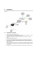
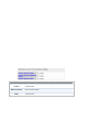
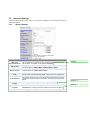
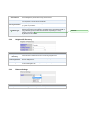
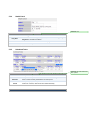
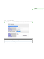
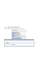
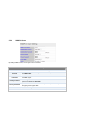
MultiAP 700G
User Manual
Aug-12
COPYRIGHT & TRADEMARKS
Specifications are subject to change without notice. Copyright © 2012 ValuePoint Networks. All Rights Reserved. ValuePoint and
the VP logo are trademarks of ValuePoint Networks. Other brands or products mentioned may be trademarks or registered
trademarks of their respective owners.
Table of Contents
1 INTRODUCTION AND SCOPE .................................................................................... 3
2 PRODUCT FEATURES ................................................................................................ 3
3 INSTALLATION............................................................................................................. 4
5.1
5.2
INSTALLATION PROCEDURES .................................................................................................. 4
QUICK START ........................................................................................................................ 6
4 INFORMATION.............................................................................................................. 6
6.1
6.2
6.3
6.4
6.5
SYSTEM ................................................................................................................................ 6
W IRELESS ............................................................................................................................. 7
WDS.................................................................................................................................... 8
EVENT LOG ........................................................................................................................... 8
NEIGHBOR APS ..................................................................................................................... 9
5 CONFIGURATION ...................................................................................................... 10
7.1
7.2
7.3
7.4
7.5
7.6
SYSTEM SETTINGS .............................................................................................................. 10
W IRELESS NETWORKS SETTINGS ......................................................................................... 16
ADVANCED SETTINGS .......................................................................................................... 26
WDS SETTINGS .................................................................................................................. 30
SNMP SETTINGS ................................................................................................................ 32
W EB ADMIN SETTINGS......................................................................................................... 35
6 DIAGNOSTIC TOOLS................................................................................................. 37
7 COMMANDS................................................................................................................ 38
8 PER USER VLAN TAGGING ..................................................................................... 40
APPENDIX A..................................................................................................................... 41
APPENDIX B..................................................................................................................... 42
1
Introduction and Scope
MultiAP 700G is a carrier-grade 802.11b/g Wi-Fi access point with centralized management system. It is
a powerful solution for building wireless networks for Wireless Internet service, wholesalers and
enterprises. Each MultiAP 700G is loaded with essential features such as Multiple SSID (virtual AP with
distinct ESSID and BSSID), VLAN, and a high-gain antenna.
One MultiAP 700G can masquerade up to 16 different access points. Each virtual access point can have
its own security policy (e.g. WPA, WPA2, etc.) and authentication mechanism (e.g. 802.1x, open, captive
portal, etc), to facilitate building your wholesale network much faster, easier and more cost-effective than
ever before. MultiAP 700G comes with a high-power Wi-Fi transmitter which greatly enhances coverage
and performance.
2
Product Features
Key features of MultiAP 700G:
Designed for wholesale wireless networks with multiple SSID and VLAN support
Independent security policies and encryption mechanisms per virtual AP
Centralized managed via web based MultiAP Central Management System (PCMS)
High-power output enhances coverage and lowers cost of ownership
WMM (Wi-Fi Multimedia) and QoS (Quality of Service) Support
WDS (Wireless Distribution System) Support
Captive Portal Support
Mesh Connector Bridging
3
Installation
MultiAP 700G acts as a bridge between the wireless and the wired Ethernet interface. A typical setup is
as follows:
3.1
1.
2.
3.
4.
5.
6.
7.
8.
Installation Procedures
Attach the antenna to the MultiAP 700G unit.
Connect the LAN port on the unit with the backbone network using an Ethernet cable. The port
could auto sense the cable is straight-through or cross-over.
Connect the power adapter to the power connector of the unit, and then plug in the power
adapter.
Wait for the status LED to turn green.
Connect a PC to the backbone network, and configure the IP address of the PC to be any IP
address between 192.168.0.4 and 192.168.0.254, with subnet mask of 255.255.255.0.
With Microsoft Internet Explorer 6 or above, or Mozilla Firefox 2.0 or above, connect to the URL
https://192.168.0.3.
When prompted, enter the default admin login ID and password: admin and public respectively.
This default username and password can be changed in the web admin. Please refer to section
5.6.2 for details.
After logging in, the following Main Menu page appears to facilitate further configuration of the
MultiAP 700G unit:
3.2
Quick Start
By default, an access point is preset with SSID: wireless
The default access point bridges the Wi-Fi interface to the Ethernet port, with both encryption and VLAN
tagging disabled.
To access the backbone network connected via the Ethernet port of the unit, establish a session at the
Wi-Fi interface with a Wi-Fi client. After establishing a Wi-Fi client session, information about the
established Wi-Fi session appears at the Web Administration Interface of MultiAP 700G, under the
section at Information-> Wireless.
4
Information
4.1
System
System Information
AP Name
This field shows the name of the system entered in the configuration.
Location
This field shows the location entered in the configuration.
Domain Name
Network IP Mode
Network IP Address
Network Subnet
Mask
Network Gateway
Network DNS
Software Versions
Serial Number
Up Time
System Time
Time Zone
Mac Address
This shows the domain name used for this system.
This shows the current IP used on the system.
This shows the current subnet mask used on the system.
Comment:
This shows the detected/assigned network gateway of the device.
Comment:
This shows the detected/assigned network DNS of the device.
This shows the current firmware version running on the system.
This shows the serial number of the device.
This shows the time has been up since boots up.
This shows the time of day in respect to the time zone selected.
This shows the time zone the system is using.
This shows the LAN MAC address of this system.
L2TP Tunnel
Status
Tunnel IP Address
Comment:
This field can be set in Configure > System. The three options available are:
DHCP, Static IP and PPPoE (Router Mode only).
This shows the status of the L2TP service.
This shows the IP acquired in the established tunnel.
Tunnel Netmask
This shows the subnet mask acquired in the established tunnel.
Firmware / Flash
Firmware Version
Flash Status
Boot from
Firmware Upgrade
Target
4.2
This shows the firmware version loaded into the flash partitions.
This shows the firmware status on the flash partitions.
This indicates which flash partition boots up the system.
This shows which flash partition is used for firmware upgrade.
Wireless
Wireless Information
Name
Number of WLANs
Current Clients
Current Channel
Current Status
This shows the system name defined in previous section.
This shows number of added SSIDs.
This indicates the number of associated clients.
This shows which 802.11 channel the system is using.
This shows the current status of the device.
Connected Clients
Manufacturer
This shows the manufacturer based on the MAC prefix.
MAC address
This shows the client MAC address.
WLAN SSID
VID
Type
Authentication
This shows which SSID the client is associated.
This shows the VLAN ID used on the SSID.
This shows the radio mode of the client.
This shows the client authentication.
Status
This shows the association status and the associated duration.
Details
This links to the detailed page of each client.
For information about the Clients Details, please refer to section 5.2.
Comment: ? any other than On?
4.3
WDS
Auto WDS Status
Bssid
This shows the wireless MAC address of the device.
Parent
This shows the parent node of the device.
Channel
This shows the channel of the existing Bssid.
Level
This shows the hop level of the device.
State
This shows the state of the node: wired or wireless.
Neighbor WDS APs
Bssid
This shows the wireless MAC address of the Neighbor WDS node.
Parent
This shows the parent node of the Neighbor WDS node.
Channel
4.4
This shows the channel of the existing Bssid.
RSSI
This shows the signal strength of the node.
Level
This shows the hop level of the node.
State
This shows the state of the node: wired or wireless.
Event Log
Upon selecting Event Log from the navigation bar on the left-hand-side of the Main Menu, the system
log is displayed. The system log is intended to provide information to aid troubleshooting in the event of
operational issues.
Comment:
4.5
Neighbor APs
Neighbor APs
Neighbor AP
Discovery
Scanning Interval
Scanning Time
This shows the feature Neighbor AP Discovery is enabled. To disable or
configure the Scanning Interval and Scanning Time options, please refer to
section 5.3.2.
This shows the scanning interval for Neighbor AP Discovery.
This shows the scanning time for Neighbor AP Discovery.
Neighbor APs
Manufacturer
This shows the manufacturer based on the MAC prefix.
SSID
This shows the ESSID of the scanned access point.
Ch
This shows the channel of the scanned access point.
RSSI
Security
This shows the signal strength of the access point.
This shows the encryption type of the access point used.
BSSID
This shows the wireless MAC address of the access point.
Last Seen
This indicates the time stamp of the access point scanned.
Status
This shows whether the access point can be detected or not.
5
Configuration
5.1
System Settings
General Access Point Settings
AP Name
A user-specified name for the access point.
This value can be retrieved via SNMP.
Location
A user-specified name for the location of the access point.
This value can be retrieved via SNMP.
AP Mode
This option enables the access point running as a bridge or a router. When
the access point runs as a router, the Management VLAN ID is ignored and
the LAN settings appear for proper network setup.
Domain Name
Domain name can be set for wireless clients to have a readable name for both
web management and captive portal redirection URLs.
Server IP
This specifies the unique IP address for the MultiAP 700G unit to communicate
on the Ethernet segment.
This IP address is distinct from the admin IP address 192.168.0.3 on the
Ethernet segment.
If Keep Default IP is set, the default IP would be available on the system
along with the Server IP setting.
If DHCP is set, the IP address of the MultiAP 700G unit is then acquired from a
DHCP server on the Ethernet segment.
If Static IP is set, it is required to enter the information related to that static IP,
including Static IP address, Subnet Mask, Default Gateway and DNS
Server.
If PPPoE is set, it is required to enter the information related to that PPPoE
connection: PPPoE Username, PPPoE Password, PPPoE Service Name.
This option is only available with Router mode.
Management VLAN
ID
This specifies the VLAN from which management sessions are allowed. The
establishment of management sessions is restricted only to the specified
VLAN ID. If Management VLAN ID is set to zero, no VLAN restriction is
applied.
The default value of this setting is zero. It means no tagging is enabled
(instead of tagged with zero).
This option is only available in Router mode.
Timezone
This option specifies the time region to be used for representing the time on
the system.
NTP Server
This is the Network Time Protocol (NTP) Server hostname to be used for
synchronizing system clock of MultiAP 700G.
The default value of this setting is pool.ntp.org.
STP
Spanning Tree Protocol, STP can be enabled to prevent path redundancy.
With this enabled, two more options are provided: Bridge Priority and
Ethernet Path Cost.
Bridge Priority
(If STP is enabled,) the parameter is set to give the likeliness for root switch
election.
Ethernet Path Cost
5.1.1
(If STP is enabled,) this gives the preference to provide the best path from the
switch to the root switch.
LAN Settings
LAN Settings will only be available when the AP Mode in the previous section had been selected as
Router mode. You can use the 700G as a DHCP server for other devices behind.
5.1.2
L2TP Tunnel Settings
L2TP Tunnel Settings
L2TP Tunnel
Enabling L2TP option on the system would start the tunnel establishment from
the access point to the server for centralized traffic management.
L2TP Server
Address
This specifies the L2TP server IP address for the access point to connect to.
L2TP/PPP
Username
This specifies the L2TP/PPP Username for tunnel authentication purpose.
L2TP/PPP Password
This specifies the L2TP/PPP Password for tunnel authentication purpose.
Tunnel IP Address
This specifies the unique IP address for the MultiAP 700G unit to communicate
over the tunnel.
If From DHCP is set, the IP address of the MultiAP 700G unit is then acquired
from a DHCP server over the tunnel. Tunnel IP Address and Tunnel Subnet
Mask will be disabled automatically.
Tunnel Subnet Mask
This setting specifies the subnet mask of the MultiAP 700G unit over the
tunnel.
Tunnel Management
VLAN
This specifies the VLAN from which management sessions are allowed over
the tunnel. The establishment of management sessions is restricted only to
the specified VLAN ID. If Management VLAN ID is set to zero, no VLAN
restriction is applied.
The default value of this setting is zero. It means no tagging is enabled
(instead of tagged with zero).
5.1.3
Security Settings
Security Settings
Layer 2
Communication
Layer 2 is in reference to the second layer in the ISO Open System
Interconnect model.
When this option is disabled, clients on the same VLAN, SSID or subnet are
not allowed to communicate directly via the Layer 2 Protocol(s). Traffic is
passed to upper communication layer(s).
With this option enabled, clients on the same VLAN are allowed to
communicate with each other directly. (Windows network resources browsing
will be possible.)
By default, the setting is enabled.
802.1X Version
This setting selects between v1 or v2 of the 802.1x EAPOL.
When v1 is selected, both v1 and v2 clients can associate with the access
point. However, when v2 is selected, only v2 clients can associate with the
access point.
Most modern wireless clients support v2. In the event that there are stations
that do not support v2, select the option v1.
By default, the value of the setting is v2.
Management from
Wireless Clients
With this option enabled, Web Admin is accessible from the Wi-Fi segment of
MultiAP 700G.
By default, it is enabled.
Syslog to Remote
Server
With this option enabled, logs are sent to an external Syslog server.
By default, this option is disabled.
Syslog Server
Address / Port
When the Syslog to Remote Server is enabled, this option is enabled for
entering the Syslog server IP address and port number.
By default, the port number is 514.
5.1.4
Radius Server Settings
Radius Server Settings
Primary Authentication
Server
Secondary
Authentication Server
Secret
When 802.1x authentication is configured, the Radius server specified by
this setting will be used for authentication.
This setting specifies the Radius server to be used for authentication in the
event that the host specified by Primary Host is unavailable.
This is the secret for accessing the Radius server.
Authentication Port
This specifies the UDP port number for the Authentication port of the
Radius server.
Primary Accounting
Server
When 802.1x authentication is configured, the Radius server specified by
this setting will be used for accounting.
Secondary Accounting
Server
Secret
Accounting Port
Re-authentication Time
Maximum
Retransmission
Radius Request Interval
This setting specifies the Radius server to used for accounting in the event
that the host specified by Primary Host is unavailable.
This is the secret for accessing the Radius server.
This specifies the UDP port number for the Accounting port of the Radius
server.
This is the re-authentication time interval. Enter 0 to disable reauthentication. By default, it is set as 0 (disable).
This specifies the maximum number of retry for RADIUS authentication. By
default, it is set as 3.
This specifies the time interval in second between each RADISU request
attempt. Note that the request time interval would be doubled every
retransmission. By default, it is set as 3s.
5.1.5
802.11b/g Profile
802.11 b/g Profile
Three options are available:
Radio Policy
•
802.11b/g (Mixed Mode): MultiAP 700G accepts both 802.11b and
802.11g client association requests.
•
802.11b Only: MultiAP 700G accepts only 802.11b client association
requests.
•
802.11g Only: MultiAP 700G accepts only 802.11g client association
requests.
Country
This setting specifies the country / region whose regulations the MultiAP 700G
unit should follow.
Users are required to choose their operating country based on their actual
location. Laws, restrictions and regulations of use of electronic goods apply to
different countries.
Available RF channels and Maximum transmission power options rely on the
selected operating country.
By default, United States is selected.
RF Channel
This option selects the 802.11 channel to be utilized.
Available options for 802.11b and 802.11g are from 1 to 11 and from 1 to 13
respectively, depend on the operating country selected in the previous option.
Tx Output Power
This option selects the transmit output power of the 700G device.
Available options are from 26 dBm to 17 dBm and 20 dBm to 11 dBm, depend
on the operating country selected in the previous option.
By default, Tx Output Power is configured to be 26 dBm.
Antenna Selection
For MultiAP 700G Outdoor units, the hardware may be equipped with two
antennas for transmit and receive diversity.
If the MultiAP 700G unit is equipped with two antennas, users can select Main,
Auxiliary and Both (Diversity) with antenna diversity.
By default, Main antenna is selected.
Comment: New feature
5.2
Wireless Networks Settings
Upon selecting Wireless Networks under Configure section from the navigation bar on the left, the
following shows the configured SSID available on the system:
General Wireless Networks Settings
Wireless Network
SSID
Default VLAN ID
Admin Status
Security Policies
BSSID
The SSID of the virtual Access Point (AP).
This setting specifies the VLAN ID to be tagged on all outgoing packets
generated from the virtual AP (i.e. packets that travel from the Wi-Fi segment,
through the MultiAP 700G unit to Ethernet segment via the LAN port).
If 802.1x is enabled, a per-user VLAN ID can be specified in the authentication
reply from the Radius server. If it is set, the value specified via Default VLAN
ID will be overridden.
This option shows whether the virtual AP is enabled or disabled.
This option shows the configured wireless authentication and encryption
methods.
This field shows the detailed BSSID.
Wireless Networks Details
Enable
Select Yes to enable the virtual AP, or No to disable the virtual AP.
By default, the virtual AP is enabled.
Wireless Network
SSID
This setting specifies the SSID of the virtual AP to be scanned by Wi-Fi clients.
The value is not case sensitive.
By default, the value is MultiAP_XXXX, where the substring XXXX in the SSID
is replaced by the last four hex digits of the LAN MAC address of the unit.
Default VLAN ID
This setting specifies the VLAN ID to be tagged on all outgoing packets
generated from the virtual AP (i.e. packets that travel from the Wi-Fi segment,
through the MultiAP 700G unit to Ethernet segment via the LAN port).
If 802.1x is enabled and a per-user VLAN ID is specified in the authentication
reply from the Radius server, then the value specified via Default VLAN ID will
be overridden.
The default value of this setting is 0. That means VLAN tagging is disabled
(instead of tagged with zero).
Broadcast SSID
This setting specifies whether or not the ESSID of the virtual AP can be
scanned by Wi-Fi clients.
Note that the BSSID (i.e. the MAC address of the virtual AP) cannot be hidden
from the scan. To associate with the virtual AP, clients must specify the correct
ESSID upon association.
Broadcast SSID is enabled by default.
Multicast Filter
This setting enables the filtering of multicast network traffic to the wireless
SSID. By default, it is set as enabled.
Multicast Rate
This setting specifies the transmit rate to used for sending multicast network
traffic.
Data Rate
There are two options on data rate: Fixed, Auto
Fixed will forced all data packets to be transmitted into the selected transmit
rate. Auto will automatically select the best transmit rate with a condition to use
the selected transmit rate as the minimum auto transmit rate.
Default Quality of
Service
The 802.1p QoS value to be marked on all outgoing packets generated from the
virtual AP (i.e. packets that travel from the Wi-Fi segment, through the MultiAP
700G unit to Ethernet segment via the LAN port).
If per-user or per-domain QoS value is specified, the Default Quality of Service
value will be overridden.
Possible values are Gold, Silver and Bronze.
This setting selects among the following options:
•
•
DHCP Server Type
•
None: DHCP requests will be passed to the Ethernet segment, and will
not be processed by MultiAP 700G.
Relay: MultiAP 700G will forward DHCP requests to a specified DHCP
Server. This option prevents broadcast messages from being
propagated on the Ethernet segment. Upon selecting this option, the
DHCP Server IP address will be prompted.
Server: MultiAP 700G will allocate and offer IP addresses locally. For
further details, please refer to Section
•
• DHCP Server
•
Please refer to the following sections, 5.2.1 and 0 for details.
Security Policy
This setting configures the wireless authentication and encryption methods.
Available options are: None, Static WEP, 802.1x and WPA.
Selecting None disables encryption.
For details on the other options, please refer to the following sections:
•
•
•
Maximum
Associated Clients
Access Control
5.2.3 - Static WEP Parameters
0 - 802.1x Parameters
5.2.5 - WPA Parameters
This setting limits the number of associations allowed to the SSID.
The default value zero would be treated as unlimited.
The settings allow administrator to control the access through Mac address
filtering.
Available options are: None, Deny all except listed, Accept all except listed.
For details on the other options, please refer to Section 5.2.6 - Access Control.
Alternative Radius
Server Setting
Captive Portal
Bandwidth
Management
The settings provide an alternative Radius setting for the SSID. With this
enabled, the settings would overwrite the Radius settings under system in
section Configure.
For details on the other options, please refer to Section 5.1.4 Radius Settings.
This setting enables the captive portal capability on the access point to do URL
redirection with different authentication. For details on the other options, please
refer to Section 5.2.7 Captive Portal Settings.
This option enables the settings to control upstream and downstream limits.
For details please refer to Section 5.2.8 – Bandwidth Management.
Alternative Layer 2
Communication
Setting
With this option enabled, 3 more options for Layer 2 Communication settings
will be available.
For details, please refer to Section 5.2.9 – Alternative Layer 2 Communication
Settings.
Wireless Network
Filter
This option enables the access point to filter network traffic based on the users’
defined rules. Users can use MAC address, IP address and protocol to form
the matching rules to perform either drop or accept policy.
For details please refer to Section 5.2.10 – Wireless Network Filters.
WMM
Mesh Connector
Bridging
5.2.1
This option enables the Wi-Fi Multimedia (WMM), as known as Wireless
Multimedia Extensions (WME) on the access point.
This option enables the transparent bridging functionality with MultiAP Mesh
Connector to achieve true layer two transparency. This option should be
checked if users want to bridge traffic from a 700G to Mesh Connector.
DHCP Server
For the setting DHCP Server Type, if the value Server is selected, DHCP Server Parameters are entered
via the following screen up selection:
Comment:
DHCP Server Parameters
IP Start Range
This setting specifies the first address in the range of IP addresses to be
assigned to DHCP clients.
IP Stop Range
This setting specifies the last address in the range of IP addresses to be
assigned to DHCP clients.
Subnet Mask
Broadcast Address
This setting specifies the broadcast address to be used by DHCP clients.
Gateway
This setting specifies the default routing gateway to be used by DHCP clients.
DNS 1
This setting specifies the IP address of the primary DNS Server to be offered
to DHCP clients.
DNS 2
This setting specifies the IP address of the secondary DNS Server to be
offered to DHCP clients.
DNS 3
This setting specifies the IP address of the tertiary DNS Server to be offered to
DHCP clients.
Domain
Lease Time
5.2.2
This setting specifies the subnet mask to be used by DHCP clients.
This setting specifies the domain name of the Wi-Fi segment.
This setting specifies the length of time throughout which an IP address of a
DHCP client remains valid. Upon expiration of the Lease Time, the assigned IP
address will no longer be valid and the renewal of the IP address assignment
will be required.
DHCP Relay
For the setting DHCP Server Type, if the value Relay is selected, DHCP relay parameters will be
available via the following screen up selection:
DHCP Relay Parameters
DHCP Server IP
This setting specifies the IP address of the DHCP server.
Comment:
5.2.3
Static WEP
The configuration of Static WEP parameters enables pre-shared WEP key encryption. Authentication is
not supported by this method.
The security level of this method is known to be weak.
Static WEP parameters are entered via the following screen upon selection:
Static WEP Parameters
Key Size
The setting can be configured as either 40 bits (64-bit WEP), 104 bits (128bit WEP) or 128 bits (152 bit WEP).
Key Format
The setting can be configured as either ASCII or HEX.
Passphrase
Combination of words and characters used to generate an encryption key.
Click Generate Key to create the key.
Encryption Key
This setting specifies a user-specified encryption key value.
For ASCII format, key length is either 5 or 13.
For HEX format, key length is either 10 or 26.
Shared Key
Authentication
This setting enables the use of shared key authentication. Open
authentication is the default authentication.
5.2.4
Comment:
802.1x Parameters
The configuration of 802.1x parameters enables Radius-based 802.1x authentication with a dynamic
WEP key. The configuration screen is as follows:
802.1x Parameters
Dynamic Key
Encryption
Key Size
Re-keying Period
Check the box to enable the Dynamic Key Encryption. Key Size and Rekeying Period will be enabled automatically.
The setting can be configured as either 40 bits or 104 bits.
This setting specifies the length of time throughout which the broadcast key
remains valid. Upon expiration of Re-keying Period, the broadcast key will no
longer be valid and the renewal of the broadcast key will be required.
Comment:
Comment:
The default value 0 means to disable re-keying.
5.2.5
WPA parameters
The configuration of WPA parameters enables WPA-TKIP or WPA2-AES.
To enable WPA and WPA-PSK, configure WPA-TKIP. To enable WPA2 and WPA2-PSK, configure
WPA2-AES.
When WPA or WPA2 is configured, Radius-based 802.1x authentication with TKIP encryption method is
enabled. Under this configuration, the Pre-Shared Key option should be disabled.
The security level of this method is known to be very high.
When WPA-PSK or WPA2-PSK is configured, a Pre-Shared Key, or Pass Phrase, is used for data
encryption and authentication. Under this configuration, the Pre-Shared Key option should be enabled.
Key length must be between 8 and 63 characters (inclusive).
The security level of this method is known to be high.
5.2.6
Access Control
The settings allow administrator to control the access through Mac address filtering.
Available options are: None, Deny all except listed and Accept all except listed.
Enter or Choose MAC address(es) in the box of MAC Insertion Tool on the right, and then click <<<Add
to list. MAC address(es) will be added into the filter.
To delete a selected MAC address in the list, click and highlight a MAC address in the box on the left,
then click Delete highlighted.
5.2.7
Captive Portal Settings
User can build and develop their own Captive Portal using PHP and then redirect all clients to the
assigned server for authentication.
Captive Portal Settings
Redirect URL
Authentication URL
This setting specifies the URL to be used to redirect the users. HTTP and
HTTPS are available for the choice of protocols.
This setting will only be available if you have chosen Plain Key
Authentication or Shared Key Authentication as the authentication method.
It specifies the authentication URL to be used. HTTP and HTTPS are available
for the choice of protocols.
Comment:
Comment:
Access Timeout
This setting specifies the allowed access time. When the timeout reaches,
users would be redirected to the “Redirect URL”.
Inactive Timeout
This option sets the value of timeout when user stays inactive.
Pass-through IPs
This setting specifies the IPs that users can go to without redirection control.
Authorized MAC
Addresses
This setting specifies the list of MAC addresses in which the authentication
and redirection are bypassed. The option is particularly useful when devices
do not have browser capability, such as wireless VoIP phone.
Authentication
Method
This setting specifies the method to do user authentication and the options are:
No Authentication, Plain Key Authentication, Shared Key Authentication,
and RADIUS Authentication.
Authentication Key
This setting specifies the authentication key which is only available when Plain
Key Authentication or Shared Key Authentication has been selected.
5.2.8
Comment: new
Bandwidth Management
Bandwidth Management
Per VAP Settings /
Per Client Settings
Upstream Limit
Downstream Limit
5.2.9
Upstream Limit and Downstream Limit can be set for each VAP or each Client.
This option set the upstream bandwidth limit. The default value 0 means
Unlimited.
This option set the downstream bandwidth limit. The default value 0 means
Unlimited.
Alternative Layer 2 Communication Setting
Comment: new
Alternative Layer 2 Communication Setting
Separate Unicast
packets
Separate Broadcast /
Multicast packets
Separate between
SSIDs
Check the box to enable the separate unicast packet feature for Layer 2
communication.
Check the box to enable the separate broadcast / multicast packets feature for
Layer 2 communication.
Check the box to enable the separate between SSIDs feature for Layer 2
communication.
Comment: new
5.2.10
Wireless Network Filters
Wireless Network Filters
Name
This setting defines the name of the filter.
Source / Destination
MAC Address
This setting specifies the source / destination MAC address(es) to be filtered.
Source / Destination
IP Address / Netmask
This setting specifies the source / destination IP address(es) and the Netmask
to be filtered.
Source / Destination
Port
This setting specifies the source / destination Port(s) to be filtered.
Protocol
This setting specifies the Protocol to be filtered.
Policy
This option defines the policy of this filter. Available options are accept and
drop.
Enable
Check the box to enable or disable this filter.
You can delete any existing filter by clicking the Remove bottom on the right of the Filter List.
5.3
Advanced Settings
Advanced Settings provides more options to fine tune the parameters on the system to achieve the
optimal performance.
5.3.1
Wireless Settings
Wireless Settings
Max. Total
Associated Clients
This value defines the maximum number of clients in total can be associated
with the device. The default number 0 means unlimited.
Beacon Rate
This setting provides the option to send beacon in different transmit bit rate
and the bit rates are: 1Mbps, 2Mbps, 5.5Mbps, 6Mbps, 11Mbps.
Beacon Interval
This setting provides the option to set the time between each beacon send.
Available options are: 100ms, 250ms, 500ms.
DTIM
This setting provides the option to set the frequency for beacon to include
Delivery Traffic Indication Message, DTIM. The interval unit is in millisecond.
RTS Threshold
This setting provides the option to set the minimum packet size for the unit to
send an RTS using the RTS/CTS handshake. Setting zero would disable this
feature.
Fragmentation
Length
This settings provides the option to set the fragmentation length.
Distance / Time
Convertor
This is a convertor to automatically adjust the Slot Time, ACK Timeout and
CTS Timeout by entering the distance between the device and the clients.
Slot Time
This setting provides the option to modify the unit wait time before it transmits.
Comment:
Comment: ???
Comment:
ACK Timeout
This setting provides the option to set the wait time to receive
acknowledgement packet before doing retransmission.
CTS Timeout
This setting provides the option to specify the timeout for the unit to wait for
CTS response in the RTS/CTS handshake.
802.11g Protection
When this option is enabled, 802.11g devices would be in favor in mixed mode
(11g and 11b) networks.
Preamble Type
Preamble Type defines the length of the CRC block for communication
between the AP device and adapters. Available options are Long and Auto. A
long preamble type can be selected if the device is operating in a ‘noisy’
network environment.
By default, it is set as Auto.
5.3.2
Neighbor AP Discovery
Neighbor AP Discovery
Neighbor AP
Discovery
Scanning Interval
Scanning Time
5.3.3
Check the box to enable the function of scanning neighbor APs.
This setting determines how often the access point goes to other channels to
discover Neighbor AP.
This setting determines how long the access point stays on the other channels
to discover Neighbor AP.
Ethernet Settings
Ethernet Settings
Speed
This setting provides the option to set the speed of the Ethernet.
Comment:
5.3.4
Health Check
Comment: new
Health Check
Method
Ping Host
5.3.5
Select Ping to enable the health check function.
Enter the IP address of Ping host. By default, the box Use default gateway as
Ping Host is checked and enabled.
Interval
This value defines the interval of health check pings.
Retries
The number of retry when the health check is failed.
Scheduled Tasks
Scheduled Tasks
Self Maintenance
The system would perform reboot based on the scheduled time selected.
Auto Channel
Selection
The system would perform auto channel selection to avoid congested channel
when no clients currently associated to the access point.
Radio On/Off
Period
This option specify the time period which radio would be switched ON or OFF.
If there are no entries, radio will be set as ON automatically.
Note
Comment: the whole section has
been updated
Schedule tasks will be started after date synchronized from NTP server.
5.4
WDS Settings
Wireless distributed system, WDS provides a way to link APs together when wired cabling is not
preferable. This also extends the wireless coverage of the wireless network for the wireless clients.
There are two options available: Auto and Manual.
5.4.1
Auto WDS Mode
Auto WDS Mode
There are three options: Auto Detect, Wired, and Wireless
•
Auto Detect - the unit would check the connectivity to the default
gateway via wired Ethernet to determine the node type. If there is
connectivity to the default gateway, the unit would state its node type
as gateway. Otherwise, the unit would state its node type as node.
•
Wired- the unit is expected to be wire-connected to provide public
network access to other wireless nodes.
•
Wireless - the unit would search for the best gateway or node
wirelessly in order to gain public network access.
Node Type
AES passphrase
This setting gives the encryption passphrase for AES encryption to secure the
date between APs. 700G devices will match this AES passphrase with each
other and for those matched will be connected for Internet connection.
Comment:
5.4.2
Manual WDS Mode
By clicking the ADD button under Manual WDS Settings, you can configure WDS connections manually.
Manual WDS Mode
Enable
MAC Address
Security Policy
This option enables this entry.
This setting gives the MAC address of the other AP to form a WDS link.
For more detail, please refer to section 5.2.3 Static WEP.
Comment:
5.5
SNMP Settings
Upon selecting SNMP Server Settings from the navigation bar on the left-hand-side of the Main Menu,
the following page is displayed to enable the configuration of SNMP server settings:
SNMP Settings
Server Name
This setting specifies the name that identifies the SNMP server.
SNMPv1
This setting specifies whether to enable or disable the support for Version 1 of
SNMP.
SNMPv2
This setting specifies whether to enable or disable the support for Version 2 of
SNMP.
SNMPv3
This setting specifies whether to enable or disable the support for Version 3 of
SNMP.
SNMP Trap
SNMP Trap is a message initiated from a client and sent to the 700G device.
Once this option is enabled, the following two options for SNMP Trap will be
available for configuration.
SNMP Trap
Receiver Name
SNMP Trap IP
Address
(When SNMP Trap is enabled) This setting specifies the SNMP Trap Receiver
Name.
(When SNMP Trap is enabled) This setting specifies the SNMP Trap IP
Address.
By clicking the New button next to SNMPv1/v2 Communities or SNMPv3 Users, you can add new
communities and users accordingly.
5.5.1
SNMPv1 / SNMPv2 Communities
By adding SNMPv1/v2 Communities, access rights can be controlled.
SNMPv1 / SNMPv2 Communities
Community Name
The “password” for getting or setting SNMP values.
IP Address and IP
Mask
The allowed subnet address who can access the SNMP server
Access Mode
Status
Choose the access mode for this community name to either Read Only or
Read & Write.
Select to Enable or Disable this community.
5.5.2
SNMPv3 Users
By adding SNMPv3 users, access rights can be controlled.
SNMPv3 User Setting
SNMPv3 User Name
The user ID to be allowed to access the SNMP agent.
Authentication
Protocol
The protocol for authenticating the user. Available options are: HMAC-MD5
and HMAC-SHA.
Authentication
Password
Only users provided with a correct password will be granted the right to access
the SNMP agent.
Privacy Protocol
Privacy Password
Access Mode
Status
The encryption method to be used in SNMPv3 communication. Available
options are: None and CBC-DES.
(When CBC-DES is chosen as the Privacy Protocol.) This is the key for
decrypting the encrypted data.
Grant Read Only or Read & Write access to this user.
Select to Enable or Disable this user.
5.6
Web Admin Settings
Upon selecting Web Admin Settings from the navigation bar on the left-hand-side of the Main Menu,
the following is displayed to enable to configuration of the parameters of the management interface:
5.6.1
Change Web Access Settings
Comment: New details
Change Web Access Settings
Web Access
Protocol
Management Port
HTTP to HTTPS
Redirection
WEB Access
Control
This option specifies the protocol for web access of the device.
By default, it is set as HTTPS.
This option configures the TCP port number of the secure web server.
By default, the TCP port number is 443.
With this option being enabled, user who accesses the web admin with HTTP
protocol will be redirected to HTTPS automatically.
Select to enable the web access control feature and the Management IP
settings will be available.
5.6.2
Change Admin Username / Password
The selection Change Admin Username / Password configures the administrator password for entering
Web Admin Interface. To change to the Username, enter the new username into the Username input
fields. To change to the password, enter the same new password into the New Password and New
Password (Retype) input fields.
5.6.3
Disable Web Administration
The selection Disable Web Administration turns off the access to Web Administration Interface.
After being turned off, Web Administration Interface can be re-enabled using SNMP.
Comment:
6
Diagnostic Tools
This provides three useful tools for diagnosing the network. The three available options are: Ping,
Traceroute and Nslookup.
7
Commands
Upon selecting Commands from the navigation bar on the left-hand-side of the Main Menu, a list of
commands is displayed, as follows:
Commands
Save Current
Configuration to
Flash
Changes made are not saved to the flash; as a result, the current configuration
will be lost after reboot.
To make the current configuration persistent across reboots, choose Save
Current Configuration to Flash.
Download Active
Configuration
Select this command to download the active configuration for backup
purposes.
Upload
Configuration
Upgrade Firmware
Select this command to upload the configuration from a backed up
configuration file.
The configuration changes are not immediately effected after uploading, but
are effected upon the selection of Activate Changes.
Select this command to upload a firmware file for upgrading the unit’s software.
A reboot is required after upgrading the firmware.
This is for activating saved changes; but note that the activation of changes
does not save the current configuration to the flash memory.
Activate Changes
Download Debug
Information File
Restore Factory
Default
Select this command to download debugging information from the MultiAP
700G unit.
In the event of technical issues, to facilitate prompt resolution by technical
support from MultiAP, please send along with a debug file with the support
request.
This command to restore the device to factory default settings. Users may
check the box to preserver network settings, including Server IP, Subnet
Mask, Default Gateway, DNS Server and Management VLAN ID). Other
configuration will be lost after the restoration.
This option is for rebooting the MultiAP 700G unit.
Reboot AP
Note
Remember to click Proceed to activate your selected commands.
Comment:
8
Per User VLAN tagging
MultiAP 700G supports VLAN tagging on per-client-session basis when 802.1x authentication is
configured. The VLAN ID can be passed from the Radius server.
The VLAN ID to be set on a client session is passed from the radius server in a vendor attribute in the
Access-Accept response called Tunnel-Private-Group-ID. When the Tunnel-Private-Group-ID attribute
is present, the default VLAN ID setting will be overwritten with the value of the attribute.
Sample Radiator Settings
This is a sample Radiator users file for enabling the Tunnel-Private-Group-ID attribute:
login_id User-Password=abc123
Tunnel-Type=1:VLAN,
Tunnel-Medium-Type=1:Ether_802,
Tunnel-Private-Group-ID=1:2,
Service-Type = Framed-User
Appendix A.
Radius Server Setup
MultiAP 700G has been test to be functional with Radiator version 3.9, using the EAP-TTLS protocol.
For MultiAP 700G, configure the authentication protocol of the virtual access point to WPA-AES:CCMP.
Sample Radiator Settings
AuthPort
1812
AcctPort
1813
LogDir
/var/log/radius
DbDir
/etc/radiator
Trace
4
<Client DEFAULT>
Secret
testing123
DupInterval 0
</Client>
<Realm DEFAULT>
<AuthBy FILE>
Filename /etc/radiator/users
EAPType TTLS
EAPTLS_CAFile /etc/1x/cert/demoCA/cacert.pem
EAPTLS_CertificateFile /etc/1x/cert/cert-srv.pem
EAPTLS_CertificateType PEM
Appendix B.
Federal Communication Commission Interference Statement
This equipment has been tested and found to comply with the limits for a Class B digital device, pursuant
to Part 15 of the FCC Rules. These limits are designed to provide reasonable protection against harmful
interference in a residential installation. This equipment generates, uses and can radiate radio frequency
energy and, if not installed and used in accordance with the instructions, may cause harmful interference
to radio communications. However, there is no guarantee that interference will not occur in a particular
installation. If this equipment does cause harmful interference to radio or television reception, which can
be determined by turning the equipment off and on, the user is encouraged to try to correct the
interference by one of the following measures:
1) Reorient or relocate the receiving antenna.
2) Increase the separation between the equipment and receiver.
3) Connect the equipment into an outlet on a circuit different from that to which the receiver is connected.
4) Consult the dealer or an experienced radio/TV technician for help.
This device complies with Part 15 of the FCC Rules. Operation is subject to the following two conditions:
(1) This device may not cause harmful interference, and (2) this device must accept any interference
received, including interference that may cause undesired operation.
FCC Caution: Any changes or modifications not expressly approved by the party responsible for
compliance could void the user's authority to operate this equipment.
IMPORTANT NOTE
FCC Radiation Exposure Statement
This equipment complies with FCC radiation exposure limits set forth for an uncontrolled environment.
This equipment should be installed and operated with minimum distance 20cm between the radiator &
your body.
This transmitter must not be co-located or operating in conjunction with any other antenna or transmitter.