1
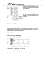
HCFA Corporation Limited
HARDWARE MANUAL
LX1NSERIES PROGRAMMABLE CONTROLLERS
Foreword............................................................................................................................. 3
1. Introduction .................................................................................................................... 6
1.1 Rules of Expansion.......................................................................................................... 7
1.2 Back up Data ....................................................................................................................7
1.2.1 EEPROM backup ................................................................................................. 7
1.2.2 Capacitor backup .................................................................................................. 7
1.2.3 Initialize Latched (Keep) Devices .............................................................................. 8
2. Installation Notes ........................................................................................................... 9
2.1 Product Outline ................................................................................................................9
2.2 LX1NRUN/STOP Control..............................................................................................10
2.3 General Specifications .................................................................................................. 11
2.4 PLC Mounting Arrangements .......................................................................................11
2.5 DIN Rail Mounting.......................................................................................................... 12
2.6 Direct Mounting .............................................................................................................. 13
2.7 Wiring...............................................................................................................................13
2.7.1 Termination at Screw Terminals ....................................................................... 13
2.7.2 Removal and installation of quick-release terminal block ............................14
2.8 Installing Optional Units ................................................................................................14
2.8.1 Expansion Boards ..............................................................................................14
3. Power Supply ............................................................................................................... 15
3.1 Wiring Techniques ......................................................................................................... 15
3.2 Wiring Cautions .............................................................................................................. 16
3.3 Power Supply .................................................................................................................16
3.4 Power Requirements..................................................................................................... 16
3.5 Example Wiring .............................................................................................................. 17
3.5.1 AC Power supply ................................................................................................17
3.5.2 24V DC Power supply........................................................................................18
3.5.3 12V DC Power Supply .......................................................................................19
3.6 Service Power supply.................................................................................................... 19
3.7 Earthing / Grounding ..................................................................................................... 19
4. Inputs ............................................................................................................................ 20
4.1 24V DC input Specifications.........................................................................................20
4.1.1 Typical Wiring ...................................................................................................... 20
4.1.2 Input Circuit Connection ....................................................................................21
4.1.3 Diodes and Inputs Connected in Series..........................................................21
4.1.4 Resistors and Inputs Connected in Parallel ...................................................21
1
HCFA Corporation Limited
4.2 AC110V Input Extension Block ....................................................................................22
5. Outputs ......................................................................................................................... 22
5.1 Output Specifications .................................................................................................... 22
5.2 Relay Output Example .................................................................................................. 22
5.2.1 Product life of relay contacts ............................................................................. 23
5.2.2 Output circuit configuration ............................................................................... 24
5.3 Transistor Output Example ...........................................................................................25
5.3.1 Transistor Output Writing Diagram (Source Type)......................................... 25
5.3.2 Japanese Model Transistor Output (Sink Type) ............................................. 26
5.3.3 Response Times ................................................................................................. 26
5.3.4 External wiring precaution .................................................................................26
6. Diagnostics................................................................................................................... 27
6.1 Preliminary Checks........................................................................................................ 27
6.2 ERROR LED ON (CPU ERROR) ................................................................................27
6.3 Common Errors.............................................................................................................. 28
6.4 Maintenance ...................................................................................................................28
6.5 Operation and Error Flags ............................................................................................28
6.6 PLC Status Registers ................................................................................................. 29
6.7 Error Registers ............................................................................................................... 29
6.8 Error Codes ....................................................................................................................30
6.9 Instruction List ................................................................................................................30
6.10 Device List ....................................................................................................................31
2
HCFA Corporation Limited
Foreword
• This manual contains text, diagrams and explanations which will guide the reader in the
correct installation and operation of the LX1N Series Programmable Controllers. It should
be read and understood before attempting to install or use the unit.
• If in doubt at any stage of the installation of an LX1NSeries Programmable Controller
always consult a professional electrical engineer who is qualified and trained to the local
and national standards which apply to the installation site.
• If in doubt about the operation or use of LX1NSeries Programmable Controller please
consult the nearest Mitsubishi Electric distributor.
• This manual is subject to change without notice.
LX1N SERIES PROGRAMMING CAUTION
Thank you for buying The HCFALX1N series controller.
Please note the following.
Notes: Block Move instruction
Applicable PLC: LX1NVer 1.00-2.10
Applicable instructions: BMOV, BMOVP(FNC15)
If the file register parameter setting and the registers D8000-D8225 are used as the
destination devices for the BMOV (BMOVP) instruction, program steps or file register data
may be lost or damaged. All other data registers can be used safely for BMOV(BMOVP)
instruction destination registers.
Program example
Guidelines for the safety of the user and protection of the LX1N.
This manual provides information for the installation and use of the LX1N. The manual
has been written to be used by trained and competent personnel. The definition of such a
person or persons is as follows;
a) Any engineer who is responsible for the planning, design and construction of automatic
equipment using the product associated with this manual should be of a competent nature,
(trained and qualified to the local and national standards required to fulfill that role). These
engineers should be fully aware of all aspects of safety with regards to automated
equipment.
b) Any commissioning or service engineer must be of a competent nature, trained and
qualified to the local and national standards required to fulfill that job. These engineers
should also be trained in the use and maintenance of the completed product. This
includes being completely familiar with all associated documentation for the said product.
All maintenance should be carried out in accordance with established safety practices.
c) All operators of the completed equipment (see Note) should be trained to use that
3
HCFA Corporation Limited
product in a safe manner in compliance to established safety practices. The operators
should also be familiar with documentation which is associated with the operation of the
completed equipment.
Note :The term ‘completed equipment’ refers to a third party constructed device which
contains or uses the product associated with this manual.
Note’s on the symbols used in this manual
At various times throughout this manual certain symbols will be used to highlight points of
information which are intended to ensure the users’ personal safety and protect the
integrity of the equipment. Whenever any of the following symbols are encountered, its
associated note must be read and understood. Each of the symbols used will now be
listed with a brief description of its meaning.
Hardware warnings
1) Indicates that the identified danger WILL cause physical and property damage.
2) Indicates that the identified danger could POSSIBLY cause physical and property
damage.
3) Indicates a point of further interest or further explanation.
Software warning
1) Indicates special care must be taken when using this element of software.
2) Indicates a special point which the user of the associate software element
should be aware of.
3) Indicates a point of interest or further explanation.
• Under no circumstances will Mitsubishi Electric be liable or responsible for any
consequential damage that may arise as a result of the installation or use of this
equipment.
• All examples and diagrams shown in this manual are intended only as an aid to
understanding the text, not to guarantee operation. Mitsubishi Electric will accept no
responsibility for actual use of the product based on these illustrative examples.
• Please contact a Mitsubishi Electric distributor for more information concerning
applications in life critical situations or high reliability.
Note Concerning the CE Marking
This document does not guarantee that a mechanical system including this product will
comply with the following standards. Compliance to EMC directive and LVD directive of
the entire mechanical system should be checked by the user / manufacturer.
4
HCFA Corporation Limited
For more details please contact the local Mitsubishi Electric sales site.
Programmable logic controllers are open-type devices that must be installed and used
within conductive control boxes.
Please use the LX1NSeries programmable logic controllers while installed in conductive
shielded control boxes.
Please secure the control box lid to the control box (for conduction).
Installation within a control box greatly affects the safety of the system and aids in
shielding noise from the programmable logic controller.
5
HCFA Corporation Limited
1. Introduction
This manual covers hardware installation instructions for the LX1NSeries PLC.
Table 1.1: LX1NMain Unit
Function Expansion Board
Communication blocks
RS_232C block
Special function blocks
RS_485 block
RS_422 block
Analogue input/output block
4 points input & 2 points output block
LX1N Basic Units
AC Power Supply
DC Power Supply
DC INPUT
Relay output
Transistor output
Points
L(mm)
W(mm)
H(mm)
LX1N-24MR(T)(24 points)
130.2
90
81
LX1N-40MR(T)(40 points)
182.2
90
83
LX1N-60MR(T)(60 points)
220.2
90
83
Table 1.1: Powered Extension Blocks
■Input
■Output
Input & output
■Special Expansion
Expansion
Positioning
Expansion
expansion
Block/Analog Unit
Block
Block
TX2N-8EX
TX2N-16EX
TX2N-8EYR
TX2N-8EYT
TX2N-16EYR
TX2N-16EYT
Analogue block
Control block
block
A/D
TX2N-2AD
TX2N-4AD
TX2N-8AD
D/A
TX2N-2DA
TX2N-4DA
6
TX2N-8ER
TX2N-16ER
TX2N-8ET
TX2N-1PG
TX2N-4PG
TX2N-10PG
TX2N-1RM-SET
TX2N-10GM
TX2N-20GM
TX0N-3A
TX2N-4AD-4DA
TX2N-4AD-2DA
TX2N-4AD-TC
TX2N-4AD-PT
TX2N-2LC
TX2N-1HC
HCFA Corporation Limited
1.1 Rules of Expansion
The maximum I/O for an LX1Nsystem is 128 I/O points and 8 special function blocks.
The LX1NSeries can be expanded as follows when used independently.
- 2 special function blocks
- 1 special function block and up to 16 I/O points
- Up to 32 I/O points
An AC powered LX1Ncan be expanded by 8 special function blocks when used in
conjunction with an HCA5extension unit (2+6).
• If a DC powered main unit is used with a power supply of less than 24VDC -15% (20.4V
DC or less), then it cannot be fully expanded by using special function blocks or powered
extension units.
It can accommodate a maximum of an additional 32 I/O points.
• If an LX1Nexpansion board is being used, it does not alter the rules of expansion
outlined above, as it utilizes special M coils for its operation and therefore does not
contribute to the maximum 128 I/O point count. Only one special function board can be
used at any time.
See section 3.8 for more details.
1.2 Back up Data
1.2.1 EEPROM backup
Data includes the Program, Comment, File Registers (D1000 ~ D7999), and parameter
data.
This will be stored as long as the EEPROM is not damaged. Mitsubishi Electric has
guaranteed a life cycle time of 10,000 writes to the EEPROM memory. Users may
experience operational writes to the EEPROM in excess of 10,000; however, due to
temperature effects a quantitative estimation cannot be given.
When saving the device status in the EEPROM, the electric power of the PLC's built-in
capacitor is used.
If the PLC has been powered on for five minutes or more, the following device data will be
saved in the EEPROM at power down: S0 ~ S127, M384 ~ M511, C16 ~ C31, C235
~C255, and D128 ~ D255.
When the EEPROM keep device status cannot be correctly saved to the EEPROM by
shortage of electric charge, at the next power-on the status of the device will be that which
saved to the EEPROM at the last save.
1.2.2 Capacitor backup
The capacitor backed memory includes M512 ~ M1535, S128 ~ S999, T246 ~ T255, C32
~ C199, C220 ~ C234, D256 ~ D7999 and the RTC.
The capacitor backed memory will retain data for a maximum of 10 days (Ambient
7
HCFA Corporation Limited
temperature: 25 °C), and requires 30 minutes to recharge upon power up.
Note: The LX1Ndoes not have battery backup, if a system requires backup of more than
10 days (Ambient temperature: 25 °C), a peripheral backup power source must be
provided.
1.2.3 Initialize Latched (Keep) Devices
• When using non-latched devices
To use the latched devices as the non-latched devices, reset the latched devices by an
initial pulse (M8002) in program.
• When using capacitor latched (keep) devices
If the voltage of a capacitor drops, the capacitor keep device status may be stored
incorrectly. Therefore, when using the PLC after it has been powered off for more than 10
days (Ambient temperature: 25 °C), re-set up the required devices and the current time
after initializing capacitor latched (keep) devices before selecting RUN.
Initialization method
Latched (keep) devices can be initialized in the PLC memory by using peripheral
equipment, and the special auxiliary relay M8032, or executing the ZRST instruction. The
two major methods are described below.
• Latch memory all clear by special auxiliary relay (M8032)
When M8032 is turned ON, all latched (keep) devices (including reset coils of timers and
counters) are cleared. M8032 can be turned ON and OFF using the forced ON/OFF
operation from peripheral equipment or within the sequence program. Note that latched
devices cannot be turned ON while M8032 is ON. When turning ON M8032 within the
sequence program, note that latched devices are cleared during END processing after
M8032 is turned ON.
Program example: This program clears all latched devices.
• Reset of device by ZRST (zone reset) instruction
The ZRST instruction can clear multiple devices at once. (Because a limited device range
can be specified for the ZRST instruction, only part of the latched (keep) devices can be
cleared at a time.)
8
HCFA Corporation Limited
However, initialization method by the ZRST
instruction for capacitor backed timer and
counter devices
(T246 ~ T255, C32 ~ C199, C220 ~ C234)
does not reset the associated coil devices.
In order to initialize the associated coil
devices, execute the RST instruction for
the coil devices being used in the user
program as shown in the example program
on the left.
2. Installation Notes
The installation of LX1Nproducts has been designed to be safe and easy. When the
products associated with this manual are used as a system or individually, they must be
installed in a suitable enclosure. The enclosure should be selected and installed in
accordance to the local and national standards.
2.1 Product Outline
Figure 2.1:Features of the LX1N PLC
①Status indicator
POWER LED: power-up state
RUN LED: running lights
ERROR LED: When program error, indicating lamp twinkles
When CPU error, indicating lamp lights
②Input indicator: LX1N is octal.
9
HCFA Corporation Limited
③Output indicator: LX1N is octal.
④RS422&485 communication port: Operating according to arrow direction
⑤RS422 communication port: Operating according to arrow direction
⑥RUN/STOP switch
⑦Terminal cover
⑧The right expansion cover
⑨The front cover, built-in battery interface
⑨Two analog potentiometer opening
2.2 LX1NRUN/STOP Control
RUN or STOP of the LX1Ncan be controlled by:
①The RUN/STOP switch mounted next to the programming port.
②A standard input (X0 to X17) defined by the system parameters.
③Remotely from a personal computer or other programming peripheral
Note: The LX1NRUN/STOP switch works in parallel with the RUN-input terminal.
Please refer to the table below.
During remote operation the LX1NRUN/STOP status is determined by the most recently
operated control.
E.g. If the RUN/STOP switch is in RUN and a remote STOP is made from a personal
computer the RUN/STOP switch must be switched to STOP then back to RUN to switch
the MPU back to RUN mode
Figure 2.2:RUN input terminal
Table : RUN/STOP selection
10
HCFA Corporation Limited
2.3 General Specifications
Power supply
Item
Power supply
Power consumption
In-rush current
Power supply(DC24V)
Input Spec.
Output Spec.
I/O & Special function expansion
Performance
Program memory
Time function
Instruction
Cycle time per log. Instruction
High speed processing
Max integrated I/O point
Auxiliary relay& timers
Counter
Others
Data registers
Analog potentiometer
Internal communication interface
communication
Specification
AC POWERED MODULE:100~240V AC DC POWERED
MODULE:DC24V
AC POWERED MODULE:30W(24M),32W(40M),35W(60M)
DC POWERED MODULE:15W(24M),18W(40M),20W(60M)
AC POWERED MODULE:30A (max.)/5ms(at
AC100V),50A/5ms(at AC200V)
DC POWERED MODULE:25A(max.)/1ms(at DC24V),
22A/0.3ms(at DC12V)
AC POWERED MODULE:DC24V 400mA
DC24V 7mA/5mA
Relay output:2A/1 point,8A/4points COM ≤AC250V, ≤DC30V
Transistor output:0.5A/1 point,0.8A/4 points COM DC5V~30V
Increase digital or analogue I/O points with expansion board
8,000 steps of built-in program memory (EEPROM),no battery
Transmit storage box available
Integrated real-time clock
Standard:27 step ladder:2 special function:89
Standard:0.5~0.7μs special:3.7~hundreds μs
I/O refresh instruction is available
134 points
Auxiliary relay:1,536 points
timer:256 points
General:200 points(16 bit) 35 points(32 bit)
High speed counters: (1 phase)60KHz/2 points,10KHz/4
points(2 phase),30KHz/1 point,5KHz/1point
General:8,000 points,Index:16 points,File:7,000 points(max.)
Built-in 2 points
RS422
RS-232C,RS-485,RS-422,N:Nnet,parallel link, PC
communication
2.4 PLC Mounting Arrangements
To prevent a rise in temperature, mount the units to walls. Never mount them to the floor
or ceiling of an enclosure.
Below (left) Single row arrangement
Caution
• Units should not be installed in areas subject to the following conditions: excessive or
conductive dust, corrosive gas (salt air, Cl2, H2S, SO2, NO2, etc.) or flammable gas,
11
HCFA Corporation Limited
moisture or rain, excessive heat, regular impact shocks or excessive vibration.
• Take special care not to allow debris to fall inside the unit during installation e.g. cut
wires, shavings etc. Once installation is complete remove the protective paper band, to
prevent overheating.
• Always ensure that mounted units and blocks are kept as far away as possible from
high-voltage cables, high-voltage equipment and power equipment.
• Do not lay signal cables near high voltage power cabling or cabinet housing along the
same trunking duct. Effects of noise or surge induction may occur. Keep signal cables of
more than 100 mm (3.94") away from these power cables.
• Install necessary power supply cut off precautions to the enclosure of the final system.
Attach a warning label (hazard symbol 417-IEC-5036) concerning electric shock to the
enclosure.
•Use the LX1Nseries PLC with consideration for electrical noise in an environment that
does not exceed conditions provided by EN50081-2 and EN61000-6-2.
• Cut off all phases from the power source before installation or performing wiring work to
avoid electric shock. Incorrect operation can lead to serious damage to the product.
• Cut off all phases from the power source before installing/removing extension or
communication cables to modules to avoid electric shock, incorrect operation or serious
damage to the product.
• Replace the terminal cover provided, after installation or wiring work is completed, and
before supplying power and operating the unit to avoid electric shock.
• After reading the manual's safety instructions, initiate the operation for making program
changes while the PLC is in RUN mode, forcing ON/OFF and switching RUN/STOP.
• The power supply of the extension units/blocks and the special function units/blocks
should be started at the same time or earlier than the LX1NSeries main unit.
• DO NOT use the “●” terminal in PLC.
• When using an incorrect power source or performing incorrect operation, serious
damage will occur regardless of the level of the voltage and frequency.
• When performing incorrect wiring or operation, serious damage will occur.
• The “L” and “N” terminals are not reversible.
If the “L” and “N” terminals are reversed, the units/blocks may be seriously damaged.
• The “24V” and “0V” terminals are not reversible.
If the “24V” and “0V” terminals are reversed, the units/blocks may be seriously damaged.
• During transportation avoid any impact as the PLC is a precision instrument.
It is necessary to check the operation of PLC after transportation, in case of any impact
damage.
• When storing the PLC, conform to the environmental conditions specified by the
general specification.
2.5 DIN Rail Mounting
Units can be snap mounted to 35mm (1.37") DIN rail (DIN 46277). To release, pull the
spring loaded clips away from the rail and slide the unit up and off.
12
HCFA Corporation Limited
2.6 Direct Mounting
Table :Hole positions
UNIT
mm
inches
± 0.2
± 0.01
A = W-8mm (0.32")
LX1N-24M☆
2-∅
82
3.23
LX1N-40M☆
( →)
122
4.81
167
6.58
LX1N-60M☆
∅= 4.5mm (0.17")
•Make sure toturn OFF the power before installing this product.
2.7 Wiring
2.7.1 Termination at Screw Terminals
Terminal screws should be tightened to between 0.5 to 0.8 N‚m. Terminal screws must be
secured to prevent a loose connection thus avoiding a malfunction.
The terminal screws for the LX1N, HCA5 Series PLCs are M3.0.When installing 1 or 2
crimp terminals to a terminal, see explanation Figure 2.5 and 2.8.
However, 3 crimp terminals or more should not be installed to a single terminal.
1) Handle the crimp terminal of the following size when 1 wire is used per terminal. Refer
to
Figure 2.5 for installation instructions
Figure 2.3:Crimp Terminal for M3.5 Screws
Figure 2.4:Crimp Terminal for M3 Screws
Figure 2.5:Installing 1 wire Per a Terminal
2) Handle the crimp terminal of the following size when 2 wires are used per terminal.
13
HCFA Corporation Limited
Refer to Figure 2.8 for installation instructions.
Figure 2.6:Crimp Terminal for M3.5 Screws
Figure 2.7:Crimp Terminal for M3 Screws
Figure 2.8:Installing 2 Wires Per a Terminal
Caution: Make sure to turn OFF the power before starting any wiring work.
2.7.2 Removal and installation of quick-release terminal block
• Removal : Loosen the left and right screws evenly.
• Installation : Tighten the left and right screws evenly.
Tightening torque 0.4 to 0.5 N•m
Make sure that the center of the terminal block is not lifted
2.8 Installing Optional Units
2.8.1 Expansion Boards
The following is a generic explanation of how to install an expansion board on to the
14
HCFA Corporation Limited
LX1NPLC.
For greater detail, specifications and wiring examples for each optional unit, please see
the relevant product manuals.
MODEL
USE WITH TX1N-EEPROM-8L
USE WITH TX1N-BAT
TX1N-EEPROM-8L
X
X
TX1N-232-BD
Possible for program upload and
Standard life of TX1N-BAT: 2
TX1N-422-BD
download
years
TX1N-485-BD
while the PLC is in the STOP mode
(at ambient temperature of
TX1N-4EX2EYT-BD
25 °C (77 °F))
TX1N-2AD-BD
For details on installation and
TX1N-1DA-BD
maintenance, etc., refer to the
TX1N-BAT USER'S MANUAL
TX1N-BAT
X
X
Always make sure the power is turned off, before installing a special function board. Only
oneboard can be used at any one time, do not try to stack multiple boards.
A) Special function or optional equipment board.
B) Optional equipment connector port.
C) M3 screw to secure board.
D) Top cover for board.
E) M3 screw to secure top cover.
Note: Do not remove this screw.
• Remove base unit top cover.
• Plug board A) into connector B).
• Fix board to base unit using screws C).
• Attach top cover for board D) removing section D)’ to
exposeconnector etc. (if applicable)
• Secure top cover with M3 screw E)
3. Power Supply
3.1 Wiring Techniques
Wiring for LX1Nproducts has been designed to be safe and easy. If the user is
concernedabout the correct installation of these products or associated products, please
contact aprofessional electrician who is trained to the local and national standards
applicable to theinstallation site.
15
HCFA Corporation Limited
3.2 Wiring Cautions
• Do not run input signals in the same multicore cable as output signals or allow
them toshare the same wire.
• Do not lay I/O signal cables next to power cables or allow them to share the same
trunkingduct. Low voltage cables should be reliably separated or insulated with regard to
highvoltage cabling.
• Where I/O signal lines are used over an extended distance consideration for voltage
dropand noise interference should be made.
3.3 Power Supply
• When wiring an AC supply, the “Live” cable should be connected to the “L”
terminal and the
“Neutral” cable should be connected to the “N” terminal. Do NOT connect the “Live” wire
tothe “N” terminal, otherwise, the user may receive a dangerous shock upon powerup.
• When wiring a DC supply the “Live” cable should be connected to the “+” terminal and
the
“Neutral” cable should be connected to the “-” terminal. Do NOT connect the “Live” wire
tothe “-” terminal, otherwise, the user may receive a dangerous shock upon powerup.
• When using a DC power supply type, it is the power source for an input extension
blockbetween "24V" and "0V" terminals.
Never supply an external power supply to these terminals.
Moreover, do not connect any equipment exceptan extension block to these terminals.
• Never connect the "0V" and the "-" terminals of a DC power supply type main unit.
3.4 Power Requirements
*1 Includes the input current(5 or 7mA per point).
*1 Includes the input current (5 or 7mA per point).
Table 4.1 :AC Power Supply Units
LX1N-24MR(T)
LX1N-40MR(T)
Power supply
100 - 240V AC +10%, -15%, 50-60Hz
Max. allowable
10ms; if less than 10ms, the PLC will continue operation.
momentary
If 10ms or more, the PLC will shut down
power failure
period
Fuse (size) rating
250V 1A
250V 3.15A (3A)
16
LX1N-64MR(T)
HCFA Corporation Limited
In-rush current
100V AC - Max. 30A for 5ms
200V AC - Max. 50A for 5ms
30W*1
Power
32W*1
35W*1
consumption
400 mA
24V DC Service
Supply
*1 Includes the input current(5 or 7mA per point.
Table 4.2 :DC Power Supply Units
LX1N-24MR(T)
LX1N-40MR(T)
Power supply
12 - 24V DC +20%, -15% (10.2 - 28.8V DC)
Max. allowable
5 ms; If less than 5 ms, the PLC will continue operation.
momentary
If 5 ms or more, the PLC will shut down
LX1N-64MR(T)
power failure
period
Fuse (size) rating
125 V 3.15A
In-rush current
24V DC - Max. 25A for 1ms
12V DC - Max. 22A for 0.3ms
Power
15W
18W
20W
consumption*1
*1 Includes the input current (5 or 7mA per point).
3.5 Example Wiring
3.5.1 AC Power supply
*1 It is recommended to use the same power source to power the main unit,
poweredextension units and special function blocks/units. If two sources are required,
follow thebelow guidelines:
- Supply power to the powered extension units and special function blocks/units beforeor
at the same time the main unit is powered.
- The power supplies may be cut the same time after ensuring system safety.
17
HCFA Corporation Limited
3.5.2 24V DC Power supply
*1 It is recommended to use the same power source to power the main unit,
poweredextension units and special function blocks/units. If two sources are required,
follow thebelow guidelines:
- Supply power to the powered extension units and special function blocks/units beforeor
at the same time the main unit is powered.
- The power supplies may be cut the same time after ensuring system safety.
*2 Never connect the "0V" and the "-" terminals of a DC power supply type main unit.
*3 When using a DC power supply type, it is the power source for an input extension
blockbetween "24V" and "0V" terminals.
Never supply an external power supply to these terminals.
Moreover, do not connect any equipment except an extension block to these terminals.
18
HCFA Corporation Limited
3.5.3 12V DC Power Supply
*1 Never connect the "0V" and the "-" terminals of a DC power supply type main unit.
*2 When using a DC power supply type, it is the power source for an input extension
blockbetween "24V" and "0V" terminals.
Never supply an external power supply to these terminals.
Moreover, do not connect any equipment except an extension block to these terminals.
3.6 Service Power supply
An AC powered LX1Ncan supply a service current of 24V DC at 400mA when used on its
ownand, when used with extension or special function blocks.
A DC powered LX1Ndoes not have the capacity to supply a service current.
HoweverAdditional extension blocks can be powered from the main units power supply.
3.7 Earthing / Grounding
Use a cable at least 0.2mm2(AWG24) to ground equipment. Ground resistance
must beless than 100Ω. Note that the ground cable must not be connected to the same
ground as the power circuits.
19
HCFA Corporation Limited
4. Inputs
4.1 24V DC input Specifications
LX1Nmain unit,extension block
X0 →X7
X10 →∞
Input voltage
24V DC ±10%
Input current
24V DC, 7mA
24V DC, 5mA
>3.5mA
Input switching
OFF →ON
>4.5mA
current
ON →OFF
<1.5mA
Response time
10ms
Variable response time
X000-X007 0-15ms
Circuit isolation
Photocoupler
Operation indication
LED is lit
-
4.1.1 Typical Wiring
Note: The input circuit power supply provides a clean+24VDC supply for the inputs.
Hence use an external+24VDC power supply at your own risk.
The input circuit power supply cannot provide aservice supply to special function blocks
(SFB). Usean external supply to power the SFBs.
When using an AC powered unit, an external 24V DCsupply can be used.
*1 When using a DC power supply type, it is the power source for an input extension
blockbetween "24V" and "0V" terminals.
Never supply an external power supply to these terminals.
Moreover, do not connect any equipment except an extension block to these terminals.
*2 Never connect the "0V" and the "-" terminals of a DC power supply type main unit.
20
HCFA Corporation Limited
4.1.2 Input Circuit Connection
LX1NMain Units
4.1.3 Diodes and Inputs Connected in Series
Vdrop across the diode Max. 4V
No more than 2 LEDs should be connected in series.
4.1.4 Resistors and Inputs Connected in Parallel
Parallel resistance Rp: LX1N= 15kΩ. If resistance Rp is less than the stated value, then
add
Rb. See equation 1 for Rb calculation.
Alternatively; Current leakage: LX1N= 1.5mA. If the current leakage is greater than the
stated value, then add Rb. See equation 2 for Rb calculation.
Parallel LED
21
HCFA Corporation Limited
4.2 AC110V Input Extension Block
5. Outputs
5.1 Output Specifications
5.2 Relay Output Example
Typical Relay
22
HCFA Corporation Limited
5.2.1 Product life of relay contacts
The product life of relay contacts considerably varies depending on the load type
used. Take care that loads generating reverse electromotive force or rush current may
cause poor contact or deposition of contacts which may lead to considerable reduction of
the contact product life.
1) Inductive load
Inductive loads generate large reverse electromotive force between contacts at shutdown
may cause arcing. At a fixed current consumption, as the power factor (phase between
current and voltage) gets smaller, the arc energy gets larger.
The test results in table 6.1 were gathered from a 1 sec ON/OFF test cycle.
Please note that the over current induced by in-rush greatly reduces the relay contacts
life.
The rated life for an inductive AC load such as a contactor or solenoid valve is 500,000
operations at 20VA.
Table 6.1:
The product life of relay contacts becomes considerably shorter than the above conditions
when the rush overcurrent is shut down.
* For countermeasures while using inductive loads, refer to "Output circuit configuration"
below in this section.
Some types of inductive loads generate rush current 5 to 15 times the stationary current at
activation. Make sure that the rush current does not exceed the current corresponding to
the maximum specified resistance load.
2) Lamp load
Lamp loads generally generate rush current 10 to 15 times the stationary current.
Make sure that the rush current does not exceed the current corresponding to the
maximum specified resistance load.
3) Capacitive load
Capacitive loads can generate rush current20 to 40 times the stationary current.
Make sure that the rush current does not exceed the current corresponding to the
maximum specified resistance load. Capacitive loads such as capacitors may be present
23
HCFA Corporation Limited
in electronic circuit loads including inverters.
* For the maximum specified resistance load, refer to Section 6.1.
5.2.2 Output circuit configuration
An internal protection circuit for the relays is not provided in the relay output circuit for this
product. It is recommended to use inductive loads with built-in protection circuits. When
using loads without built-in protection circuits, insert an external contact protection circuit,
etc. to reduce noise and extend the product life.
1) DC load
Connect a diode in parallel with the load.
The diode (for commutation) must comply with
the following specifications.
2) AC load
Connect the surge absorber shown to the right (combined CR components such as a
surge killer and spark killer, etc.) parallel to the load.
Select the rated voltage of the surge absorber suitable to the output used. Refer to the
table below for other specifications.
3) Interlock
For loads such as forward/reverse contactors, etc., where a hazardous condition could
result if switched
ON simultaneously, an external interlock should be provided for interlocking the PLC's
internal programs as shown to the right.
24
HCFA Corporation Limited
4) In-phase
PLC output contacts (*) should be used in an "in-phase" manner.
5.3 Transistor Output Example
5.3.1 Transistor Output Writing Diagram (Source Type)
25
HCFA Corporation Limited
5.3.2 Japanese Model Transistor Output (Sink Type)
5.3.3 Response Times
OFF times increase as the load current decreases.
For improved response times use a ‘dummy’ resistor, see the figure below. If a response
time of 0.5 ms or better is required when using ‘light
loads’ use a ‘dummy’ resistor and ensure the signal
line has a current greater than 60mA/24V DC
Y000 and Y001 are high speed response outputs with
the following characteristics:
10 - 100mA at 5 - 24V DC, 100kHz maximum output
signal.
If a high speed response is required, a current of 10 - 100mA must be used.
5.3.4 External wiring precaution
1) Contact protection circuit for inductive loads
Transistor outputs use internal zener diode (50V) as
protection circuitry. When driving the inductive load with
transistor output, a reverse-current protection diode can
be installed in parallel with the load if necessary.
The reverse-current protection diode needs to satisfy the
following specifications.
- Choose a commutating diode that has a reverse voltage strength over 5 - 10 times the
load voltage, and a forward current over the load current.
26
HCFA Corporation Limited
2) Mechanical Interlock
Ensure all loads are applied to the same side of
each PLC output, see previous figures. Loads
which should NEVER simultaneously operate
(e.g. direction control of a motor), because of a
critical safety situation, should not rely on the
PLC’s sequencing alone. Mechanical interlocks
MUST be fitted to all critical safety circuits.
(See proceeding figure.)
6. Diagnostics
6.1 Preliminary Checks
6.2 ERROR LED ON (CPU ERROR)
27
HCFA Corporation Limited
6.3 Common Errors
- Corroded contact points at some point in an I/O line.
- An I/O device has been used outside its specified operating range.
- An input signal occurs in a shorter time period that taken by one program scan.
6.4 Maintenance
- Check interior temperature of the panel.
- Check panel air filters if fitted.
- Check for loosening of terminals or mounting facilities (due to vibration)
6.5 Operation and Error Flags
28
HCFA Corporation Limited
6.6 PLC Status Registers
6.7 Error Registers
29
HCFA Corporation Limited
6.8 Error Codes
6.9 Instruction List
30
HCFA Corporation Limited
6.10 Device List
Item
Program capacity
Specification
8k steps
Remarks
Provided by built in EEPROM
memory
I/O configuration
Max hardware I/O configuration points 128, dependent on user
selection
(Max. software addressable Inputs 128, Outputs 128)
Auxiliary relay
General
384 points
M0 to M383
(M coils)
Latched
1152 points
M384 to M1535
(EEPROM
EEPROM keep: 128 points
EEPROM keep: M384 to M511
backed-up)
Capacitor keep: 1024 points
Capacitor keep: M512 to M1535
Special
256 points
From the range M8000 to M8255
State relays
Latched
1000 points
S0 to S999
(S coils)
(EEPROM
EEPROM keep: 128 points
EEPROM keep: S0 to S127
backed-up)
Capacitor keep: 872 points
Capacitor keep: S128 to S999
Initial
10 points (subset)
S0 to S9
100 msec
200 points
T0 to T199
Timers ()
Range: 0 to 3,276.7 sec
10 msec
46 points
T200 to T245
31
HCFA Corporation Limited
Range: 0 to 327.67 sec
Counters (C)
1 msec
4 point, Capacitor keep
retentive
Range: 0 to 32.767 sec
100 msec
6 points, Capacitor keep
retentive
Range: 0 to 3,276.7 sec
General
16 points
C0 to C15
Range: 1 to 32,767 counts
Type: 16 bit up counter
Latched
184 points
C16 to C199
(EEPROM
Range: 1 to 32,767 counts
EEPROM keep: C16 to C31
backed-up)
EEPROM keep: 16 points
Capacitor keep: C32 to C199
Capacitor keep: 168 points
Type: 16 bit up counter
20 points
C200 to C219
Range: -2,147,483,648 to
Type: 32 bit bi-directional counter
General
T246 to T249
T250 to T255
2,147,483,647 counts
Latched
15 points, Capacitor keep
C220 to C234
(EEPROM
Range: -2,147,483,648 to
Type: 32 bit bi-directional counter
backed-up)
2,147,483,647 counts
High speed
1 phase
Range: -2,147,483,648 to
C235 to C240, 6 points
counters (C)
1 phase
+2,147,483,647 counts
C241to C245, 5 points
Max. 6 points
c/w start
General rule: Select counter
stop input
combinations with a combined
2 phase
counting frequency of 60kHz or
C246 to C250, 5 points
A/B phase
less.
C251 to C255, 5 points
Note;
all
counters
are
latched
(EEPROM backed-up) If high
speed counter is used with
the
HSCS
or
instruction,
a
counting
frequency
HSCR
combined
of
30kHz or less
Data
General
128 points
D0 to D127
registers (D)
Type: 16 bit data storage register
pair for 32 bit device
Latched
7872 points
D128 to D7999
(EEPROM
EEPROM keep: 128 points
EEPROM keep: D128 to D255
backed-up)
Capacitor keep: 7744 points
Capacitor keep: D256 to D7999
Type: 16 bit data storage register
pair for 32 bit device
File
Maximum 7000 points
D1000 to D7999 set by parameter
in
14 blocks of 500 program steps
Type: 16 bit data storage register
32
HCFA Corporation Limited
Externally
2 points
D8030 & D8031
adjusted
Range: 0 to 255
Data is entered indirectly through
the
external setting potentiometer
Special
256 points
(inclusive
From the range D8000 to D8255
of
D8030
and
Type: 16 bit data storage register
D8031)
Index
16 points
V and Z
Type: 16 bit data storage register
Pointers (P)
For use
128 points
P0 to P127
6 points
I00❏to I50❏
with CALL
For use with
(rising trigger ❏= 1,
interrupts
falling trigger ❏= 0)
Nest levels
8 points for use with MC and
N0 to N7
MCR
Constants
Decimal K
16 bit: -32,768 to +32,767
32 bit: -2,147,483,648 to +2,147,483,647
Hexadecimal
16 bit: 0000 to FFFF
H
32 bit: 00000000 to FFFFFFFF
33