1
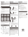
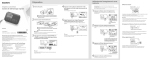
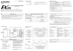
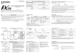
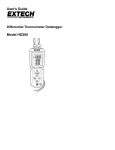
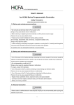
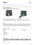
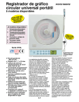
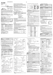
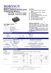
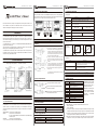
1
TX2N-4AD-PT User’s Manual
2
TX2N-4AD-PT User’s Manual
3.2 Special function block numbers
2N-4AD-PT
TX2N-4AD-PT User’s Manual
5.3 Performance specification
Other special units of blocks that use FROM/TO instructions, such as analog input blocks,
analog output blocks and high-speed counter blocks, can be directly connected to the main
unit of the PLC or to the right side of other extension blocks or units.
User’s Manual
3
Analog Inputs
Centigrade
Fahrenheit
Both °C and °F are available by reading the appropriate buffer memory (BFM).
Item
Analog input
signal
This manual contains texts, diagrams and explanations which will guide the reader in the
correct installation and operation of TX2N-4AD-PT. This manual should be read and
understood carefully before attempting to install or use the unit.
Platinum Temperature Pt 100 sensors (100 Ω), 3-wire, 4-channel
(CH1, CH2, CH3, CH4), (DIN 43760, JIS C 1604-1997, JIS C 1604-1981)
Current to sensor
TX2N-4DA-PT
1 mA. sensor: 100 ΩPt 100
Compensated
range
-100°C to +600°C
-1000 to 6000
-1480 to +11120
12-bit conversion 11 data bits +1 sign bit 16-bit binary with sign
Digital output
1. Introduction
TX2N-32ER
X050-X067
Y030-Y047
• The TX2N-4AD-PT analog block amplifies the input from four platinum temperature
sensors (Pt 100, 3 wire, 100 Ω) and converts the data into 12 bit reading’s stored in the
main unit. Both Centigrade (°C) and Fahrenheit (°F) can be read. Reading resolution is 0.2°C
to 0.3°C / 0.36°F to 0.54°F.
• The TX2N-4AD-PT can connected to the LX1N/HCA2/HCA5/TX3U/HCA8/HCA8C series
Programmable Controllers (PLC).
• All data transfers and parameter setups are adjusted via software control of the TX2N4AD-PT; by use of the TO/FROM applied instructions in the PLC.
• The TX2N-4AD-PT occupies 8 I/O points on the PLC expansion bus. The 8 I/O points can
be allocated from either inputs or outputs. The TX2N-4AD-PT draws 30mA from the 5V rail
of the main unit or powered extension unit.
Minimum
resolvable temp.
0.2°C to 0.3°C
Conversion speed
4. Wiring
0.36°F to 0.54°F
± 1% full scale (compensated range)
See section 7.0 for special EMC considerations
Overall accuracy
60ms (15 ms for 4 channels)
Analog Inputs continued...
4.1 Wiring
2. External dimensions
Weight: Approx. 0.3 kg (0.66 lbs)
TX2N-4AD-PT
Special block
No.2
-148°F to +1112°F
Dimensions: mm (inches)
TX2N-4AD-PT
① The cable of the Pt 100 sensor or a twisted shielded
cable should be used for the analog input cable. This
analog input cable should be wired separately from
power lines or any other lines which may induce noise.
The three wire method improves the accuracy of the
sensors by compensating voltage drops.
② If there is electrical noise, connect the FG (frame
ground) terminal with the ground terminal. (In CH1,
there is no FG terminal. Use FG terminal of other
channels.
③ Connect the ground terminal on the TX2N-4AD-PT
unit with the grounded terminal on the main unit. Use
grounding on the main unit, if grounding is possible.
④ Either an external or the 24V built-in supply in the PLC
may be used.
+11,120
Digital
output
-100℃
-1,000
Digital
output
-148°F
+600℃
-1,480
Temp.input℃
+1,112°F
Temp.input°F
Miscellaneous
Specification
Item
Isolation
Photo-coupler isolation between analog and digital circuits.
DC/DC converter isolation of power from the main unit.
No isolation between analog channels
Number of occupied I/O points
The block occupies 8 I/O points
(can be either inputs or outputs)
For additional data regarding EMC considerations
please see section 10.
6. Allocation of buffer memories (BFM)
6.1 Buffer memories
4.2 Using crimp terminations
TX2N-4AD-PT
TX2N-4AD-PT
Use crimp terminals as indicated on the left.
Secure the terminal using a tightening torque of
between 0.5 and 0.8N·m.
Wire only to the module terminals discussed in this
manual. Leave all others vacant.
3. Connection with PLC
+6,000
Conversion
Characteristics
5. Installation notes and usage
3.1 Connection with PLC
BFM
*#0
*#1 - #4
#5 - #8
#9 - #12
#13 - #16
#17 - #20
#21 - #27
*#28
#29
#30
#31
CONTENTS
Characteristic change
Ch1 to CH4 Averaged temperature reading to
be averaged (1 to 256) Default = 8
Ch1 to CH4 Averaged temperature in 0.1°C units
Ch1 to CH4 Present temperature in 0.1°C units
Ch1 to CH4 Averaged temperature in 0.1°F units
Ch1 to CH4 Present temperature in 0.1°F units
Reserved
Digital range error latch
The TX2N-4AD-PT communicates
with the PLC via buffer memories.
BFMs (buffer memories) #21 to
#27 and #31 are reserved.
All BFM data can be read by the
PLC using the FROM instruction.
PLC can read/write the BFMs
(marked with “*” ), using FROM
/TO instructions.
Error status
Identification code K2040
Reserved
5.1 General specification
The TX2N-4AD-PT unit can be connected to the PLCs as follows. Restrictions apply to the
maximum number of connectable units, depending on the DC24V/DC5V Power Supply
capacities and the Main Unit/ Special Function Unit types. For details, refer to the respective
PLC manual.
HCA5/HCA8/TX3U : The maximum connectable units is 8.
HCA8C*1
: The maximum connectable units is 8.
To connect the TX2N-4AD-PT with the HCA8C main unit, HCA8C-CNV5V
-TX2N is required.
LX1N/HCA2
: The maximum connectable units is 8.
*1 Up to 7 units can be connected to an HCA8C-16X16YT PLC.
Item
General specifications
Dielectric withstand voltage
Specification
Same as those for the main unit
500V AC, 1min (between all terminals and ground)
5.2 Power supply specification
Item
Specification
Analog circuits
24V DC ± 10%, 50mA
5V DC, 30mA (internal power supply from the main unit)
Digital circuits
1) BFM #0 value (K0 or K1) decides the Pt100 characteristic to be used.
K0 : JIS C 1604-1997
K1 : JIS C 1604-1981
2) The number of samples to be averaged are assigned in BFMs #1 to #4. Only the range
1 to 4096 is valid. Values outside this range are ignored. The default value of 8 is used.
3) A number of recently converted readings are averaged to give a smoother read out.
The averaged data is stored in BFMs #5 to #8 and #13 to #16.
4) BFMs #9 to #12 and #17 to #20 store the current value of the input data. This value is
in units of 0.1°C or 0.1°F, but the resolution is only 0.2°C to 0.3°C or 0.36°F to 0.54°F.
4
TX2N-4AD-PT User’s Manual
5
TX2N-4AD-PT User’s Manual
8. Example program
6.2 Status Information
1) Buffer Memory BFM #28: Digital range error latch
BFM #29 b10(digital range error) is used to judge whether the measured temperature is
within the unit’s range or not.
BFM #28 latches the error status of each channel.
b15 or b8
Not used
b7
High
b6
Low
b5
High
CH4
b4
Low
b3
High
CH3
b2
Low
b1
High
CH2
b0
Low
CH1
Low : Latches ON when the temperature measurement data drops below the lowest
temperature measurement limit.
High : Turns ON when the temperature measurement data rises above the highest
temperature measurement limit.
In the program shown below, the TX2N-4AD-PT block occupies the position of special block
number 2 (that is the third closest block to the PLC). The averaging amount is four. The
averaged values in degrees C of input channels CH1 to CH4 are stored respectively in data
registers D0 to D3.
M8002
Initialization
Pulse
FNC78
FROM
M8000
RUN
monitor
Block No.2 BFM #30 →(D10)
Identification code
K1
When (K2040) = (D10), M1 = ON
i.e. When identification code is K2040, M1 = ON
M0
FNC78
FROM
K2
Block No.2 BFM #29 →(K4M10)
Transfer the error status to (M25 to M10).
When error is found, M10 = ON.
K29 K4M10 K1
M10
Y010
ON
Bit devices of BFM #29
D10
This initial step checks that the special function block placed at position 2 is actually a
TX2N-4AD-PT, i.e. its unit identification number is 2040 (BFM #30).
This step is optional, but it provides a software check that the system has been
configured correctly.
When an error occurs the temperature data before the error is latched. If the measured
power.
2) Buffer Memory BFM #29: Error status
K30
FNC10
CMP K2040 D10
value returns to within valid limits the temperature data returns to normal operation. (Note:
The error remains latched in (BFM #28))
An error can be cleared by writing K0 to BFM #28 using the TO instruction or turning off the
K2
b0 : Error
When either b2 or b3 is ON
A/D conversion is stopped
for the error channel
No error
b1 : Reserved
b2 : Power source
Reserved
24V DC power supply failure.
Reserved
Power supply normal
b3 : Hardware error
A/D converter or other hardware
failure
Hardware Normal
b4 to b9 : Reserved
Reserved
Reserved
b10 : Digital range error
Digital output/analog input
value is outside the specified
range
Digital output value is normal.
b11 : Averaging error
Selected number of averaged
results is outside the available
range -see BFM #1 to #4
Averaging is normal.
(between 1 to 4096)
b12 to b15 : Reserved
Reserved
Reserved
#30 using the FROM instruction. This number for the TX2N-4AD-PT unit is K2040.
The PLC can use this facility in its program to identify the special block before commencing
7. System block diagram
This step provides optional monitoring of the TX2N-4AD-PT Error Buffer Memory (#29). If
there is an Error on the TX2N-4AD-PT, bit b0 of BFM #29 will be set on.
This can be read by this program step, and output as a bit device in the PLC (Y010 in this
example). Additional Error devices can be output in a similar manner, i.e. b10 BFM #29.
(see below)
M8000
FNC78
FROM
K2
K29 K4M10
K1
M10
Y010
Represents b0 BFM #29
Y011
Represents b10 BFM #29
M20
3) Buffer Memory BFM #30: Identification Code
The identification code or ID number for this Special Block is read from buffer memory BFM
data transfer from and to the special block.
Represents b0 BFM #29
OFF
M1
or
M8000
FNC79
TO
K2 K1 K4
FNC78
FROM
K2 K5 D0 K4
(K4) →(BFM #1 to #4)
Number of samples is changed to four on CH1 to Ch4
K4
(BFM #5 to #8) →(D0 to D3)
Transfer the averaged temperature
value in °C to the data registers.
This step is the actual reading of the TX2N-4AD-PT input channels. It is essentially
the only program step which is needed. The "TO" instruction in this example, sets
the input channels, CH1 to CH4, to take the average reading of four samples.
The "FROM" instruction reads the average temperatures (BFM #5 to #8) for input
channels CH1 to CH4 of the TX2N-4AD-PT. If direct temperature readings are
required BFM #9 to #12 should be read instead, ex.
FNC78
FROM
K2
K9
D0
special
block No.2
TX2N-4AD-PT
BFM number
result
destination
K4
No. of
words read
9. Diagnostics
9.1 Preliminary checks
I. Check whether the input/output wiring and/or extension cables are properly connected
on the TX2N-4AD-PT analog special function block.
II. Check that the PLC system configuration limits have not been exceeded, i.e. the number
of special function blocks, and the total system I/O are within the specified range.
III. Ensure that the correct operating range has been selected for the application.
IV. Check that there is no power overload on either the 5V or 24V power sources, remember
TX2N-4AD-PT Analog Block
the loading on main unit or a powered extension unit varies according to the number of
extension blocks or special function blocks connected.
V. Make sure that the main unit has been switched to RUN
6
TX2N-4AD-PT User’s Manual
9.2 Error checking
If the TX2N-4AD-PT special function block does not seem to operate normally, check the
following items.
Check the status of the POWER LED.
Lit
: The extension cable is properly connected.
Otherwise : Check the connection of the extension cable.
Check the external wiring.
Check the status of the “24V” LED (top right corner of the TX2N-4AD-PT).
Lit
: TX2N-4AD-PT is ON, 24V DC power source is ON.
Otherwise : Possible 24V DC power failure, if ON possible TX2N-4AD-PT failure.
Check the status of the “A/D” LED (top right corner of the TX2N-4AD-PT).
Lit
: A/D conversion is proceeding normally.
Otherwise : Check buffer memory #29 (error status). If any bits (b0, b2, b3) are ON,
then this is why the A/D LED is OFF.
10. EMC Consideration
Electromagnetic compatibility or EMC must be considered before using the TX2N-4AD-PT.
HCFA recommend that the PT 100 sensors used, should be fitted with a form of seild or
screening as protection against EMC noise.
If some form of cable protection is used, the“Shield”must be terminated at the FG
terminals as shown in section 4.1.
Because of the delicate nature of all analog signals, failure to take good EMC precautions
could lead to EMC noise induced errors; up to ±10% of actual values. This is an absolute
worst case figure, users who do take good precautions can expect operation within normal
tolerances.
EMC considerations should include selection of good quality cables, good routing of those
cables away from potential noise sources.
Additionally it is recommended that signal averaging is used as this will reduce the effects of
random noise “spikes”.