1
D3128 Spatial Light Modulator
User’s Manual
Revision 1.04
D3128 Spatial Light Modulator
Quick Setup Guide
1. Install the PixelDRIVE 3000 software on a PC running Microsoft® Windows® (98SE or later). Place the
included CD in the CD-ROM drive. Wait for the PixelDRIVE menu to appear, then click on the “Install
PixelDRIVE …” button.
2. Connect the D3128 control module (USB connector) to a PC (USB port) using the included USB cable.
3. With the SLM optics head positioned as desired, connect the optics head to the control module using the
included 25-pin cable.
4. Plug the power supply cable into the power connector on the D3128 control module. Connect the power
supply to a properly grounded outlet.
5. If array updates are to be synchronized to other experiment equipment, connect the TRIGGER output SMB
terminal to the high-impedance trigger input of other laboratory devices.
6. Power on the D3128 control module. The POWER light will illuminate and the STATUS light will blink
the firmware version during initialization. After initialization, the STATUS light will go off. The POWER
light remains illuminated until the power is turned off.
7. The first time the unit is powered on, Windows® will detect new hardware and prompt for a driver. The
driver files are on the PixelDRIVE 3000 CD. For Windows® 2000 and Windows® XP, drivers are in the USB
DRIVERS\WIN2K_XP directory. The drivers for Windows® 98SE and Windows® ME are in the USB
DRIVERS\WIN98_ME directory.
8. Start the PixelDRIVE 3000 software by clicking Start|Programs|Meadowlark Optics|PixelDRIVE 3000.
D3128 User’s Manual rev. 1.04
ii
D3128 Spatial Light Modulator
Table of Contents
Quick Setup Guide ....................................................................................................................................... ii
Table of Contents ........................................................................................................................................iii
1. Nematic Liquid Crystal Technology: The Basics.................................................................................... 1
1.1 Nematic LCVR Physical Architecture ........................................................................................ 1
1.2 Building a Liquid Crystal Pixel Array ........................................................................................ 3
2. Hardware Setup and Configuration........................................................................................................ 3
2.1 Laboratory and System Requirements for the D3128 .................................................................. 3
2.2 Setup Procedure for the D3128................................................................................................... 3
3. Hexagonal 127-Pixel Array ..................................................................................................................... 4
3.1 PixelDRIVE 3000 Software for the Hexagonal Array ................................................................. 4
3.1.1 Main Functions ......................................................................................................... 6
3.1.2 Frame Control ........................................................................................................... 6
3.1.3 Hex Frame Generation............................................................................................... 7
3.1.4 Hex pattern Adjust..................................................................................................... 8
3.1.5 Temperature Control ................................................................................................. 8
3.1.6 On-Screen Pixel Array............................................................................................... 8
3.2 The Indexing Convention of the Hexagonal Pixel Array. ............................................................ 8
4. Linear 128-Pixel Array............................................................................................................................ 9
4.1 PixelDRIVE 3000 Software for the Hexagonal Array ................................................................. 9
4.1.1 Main Functions ....................................................................................................... 11
4.1.2 Frame Control ......................................................................................................... 11
4.1.3 On-Screen Pixel Array............................................................................................. 12
4.1.4 Temperature Control ............................................................................................... 12
4.1.5 Single-Pixel Select/Control...................................................................................... 12
4.1.6 Pattern Generation................................................................................................... 12
4.1.7 Pattern Adjustment .................................................................................................. 12
5. User Development with LabVIEW™ VI’s Provided by Meadowlark Optics, Inc. .............................. 13
6. Care and Maintenance of the SLM Optics............................................................................................ 13
7. Frequently Asked Questions ................................................................................................................. 13
Appendix A: Pixel Data File Formats ....................................................................................................... 15
Appendix B: Firmware Updater ............................................................................................................... 17
Appendix C: Software licensing................................................................................................................ 21
Software License Agreement .......................................................................................................... 21
Trademarks .................................................................................................................................... 23
D3128 User’s Manual rev. 1.04
iii
Information in this document is subject to change without notice. Meadowlark Optics may have
patents, patent applications, trademarks, copyrights, or other intellectual property rights covering
subject matter in this document. Except as expressly provided in any written license agreement from
Meadowlark Optics, the furnishing of this document does not give you any license to these patents,
trademarks, copyrights, or other intellectual property. Please contact Meadowlark Optics for a list of
applicable patents, trademarks, and/or copyrights.
Copyright © 2010 Meadowlark Optics, Incorporated. All rights reserved.
Printed in the United States of America.
D3128 User’s Manual rev. 1.04
iv
D3128 Spatial Light Modulator
The D3128 from Meadowlark Optics, Inc. is a complete liquid crystal spatial light modulator solution. The
optical head includes the LC pixel array, configured in either a 128-pixel linear or 127-pixel hexagonal
geometry. The LC is thermally stabilized by two independent temperature feedback control sub-circuits.
The optical head mounts in a laboratory setup using standard ¼-20 or 8-32 hardware, and it electrically
connects to a compact control module by one convenient 25-pin cable. The control module includes an
output trigger channel for integrating the SLM with other laboratory equipment, and connects easily to a
PC with a USB cable. The software provides control of individual pixels as well as functions that treat the
array as a whole, dual-channel temperature control, multiple frame configuration, timing control, and file
I/O, all through an attractive, user-friendly interface. The CD includes LabVIEW™ development resources
for customers wishing to design control features using National Instruments LabVIEW™.
1. Nematic Liquid Crystal Technology: The Basics
1.1 Nematic LCVR Physical Architecture
Typical nematic Liquid Crystal Variable Retarders (LCVRs) such as the LVR- and LRC- series by
Meadowlark Optics are constructed using optically flat fused silica windows coated with transparent
conductive indium tin oxide (ITO). A thin dielectric layer is applied over the ITO and gently rubbed, creating
parallel micro-grooves for liquid crystal molecular alignment. Two windows are then carefully aligned and
spaced a few microns apart. The cavity is filled with birefringent nematic liquid crystal material. Electrical
contacts are attached and the device is environmentally sealed.
Anisotropic nematic liquid crystal molecules form uniaxial birefringent layers in the liquid crystal cell. An
essential feature of nematic material is that, on average, molecules are aligned with their long axes parallel, but
with their centers randomly distributed, as shown in Fig. 1. With no voltage applied, the liquid crystal
molecules lie parallel to the glass substrates and maximum retardation is achieved.
Fused Silica
ITO
Alignment Layer
a.
Maximum
Retardance
(V=0)
Spacer
LC Molecules
b.
Minimum
Retardance
(V>>0)
LC Molecules
tipped with
applied voltages
Figure 1. Liquid Crystal Variable Retarder construction showing molecular alignment (a) without and
(b) with applied voltage (drawing not to scale)
D3128 User’s Manual rev. 1.04
1
When voltage is applied, liquid crystal molecules begin to tip perpendicular to the fused silica windows. As
voltage increases, molecules tip further causing a reduction in the effective birefringence and hence,
retardance. Molecules at the surface, however, are unable to rotate freely because they are pinned at the
alignment layer. This surface pinning causes a residual retardance of ~30 nm even at high voltage (20 volts).
We achieve zero (or any custom) retardance with a subtractive fixed polymer retarder, called a compensator,
attached to the liquid crystal cell. Negative retardance values are sometimes preferred for example, when
converting between right- and left-circularly polarized states. Fig. 2 illustrates retardance as a function of
voltage for a typical LCVR with and without an attached compensator. Placing a compensated LCVR between
two high extinction polarizers creates an excellent optical attenuator, with convenient electronic control.
Figure 2. Liquid Crystal Variable Retarder performance at 632.8 nm, 21°C (a) without compensator,
and (b) with compensator
As with any birefringent material, retardance is dependent upon thickness and birefringence. Liquid crystal
material birefringence depends on operating wavelength, drive voltage, and temperature. The overall
retardance of a liquid crystal cell decreases with increasing temperature (approximately -0.4% per °C).
Liquid crystal devices should be electrically driven with an AC waveform with no DC components to prevent
ionic buildup which can damage the liquid crystal layer. LCVR’s from Meadowlark Optics for instance
require a 2 kHz square wave with a zero-average voltage. Retardance is controlled by varying the peak-topeak voltage from zero to ±10V.
D3128 User’s Manual rev. 1.04
2
1.2 Building a Liquid Crystal Pixel Array
The conductive ITO layers of a typical LC cell are uniform so that an applied square-wave voltage signal
establishes a uniform electric field throughout the LC-filled region of the cell. With a spatial light modulator,
the conductive ITO on one piece of glass is etched into a pattern much like the copper layer of a printed circuit
board is etched into a pattern that is useful for the desired circuit design. The ITO on the other piece of glass is
uniform to provide a common ground. The etched piece has ITO in the desired pixel pattern, and traces that
electrically connect each pixel to the edge of the glass. The SLM LC cell is assembled and filled in the same
manner as a variable retarder. A unique type of multi-conductor cable adheres to the glass and electrically
connects the array of pixel connectors to the circuit that drives them.
2. Hardware Setup and Configuration
2.1 Laboratory and System Requirements for the D3128
• 100-240 VAC, 47-63 Hz 500 mA utility power.
• A PC with an available USB port.
• Minimum PC requirements to run the included PixelDRIVE 3000 software are a Pentium® processor,
64 MB RAM, 20 MB hard drive space, 800x600 pixel, 16-bit color graphics, a CD-ROM, and
Microsoft® Windows® 98SE, ME, 2000 or XP.
• Recommended PC specifications are a 1-GHz Pentium® III processor, 256 MB RAM, 20 MB hard
drive space, 1024x768 pixel, 16-bit color graphics, a CD-ROM, and Microsoft® Windows® 2000 or
XP.
2.2 Setup Procedure for the D3128
1. Unpack controller and cables from shipping container. Please verify that your shipment included:
• D3128 controller unit
(1)
• SLM optical head unit
(1)
• 25-conductor optical head cable
(1)
• +12V power supply and power cable (1 unit with +12V cable attached and 1 AC power cable)
• USB cable
(1)
• PixelDRIVE 3000 software CD
(1)
• User’s manual
(1 printed copy)
2.
Hardware configuration of the D3128 control module:
• Position the SLM optical head securely on an optics table or breadboard. The optical head has
two 8-32 tapped holes on all four edges, as well as ¼-20 tapped holes on two edges for mounting
the SLM optical head with standard optics hardware.
• Connect the 25-pin optical head cable to the optical head. The optical head connector is keyed to
disallow improper insertion. Connect the other end of the optical head connector to the D3128
control module.
• Connect the +12VDC supply to the D3128 control module. Plug the power supply into a
properly grounded AC outlet.
• Attach the USB cable to the USB connector on the rear of the D3128 control module, and
connect the other end to an available USB port on a PC.
• If synchronizing array updates to other experiment equipment, connect the TRIGGER output
SMB terminal to the high-impedance trigger input of other laboratory devices.
D3128 User’s Manual rev. 1.04
3
1
6
Start
Pi xelDRIV E 3000
11:58 P M
4
2
3
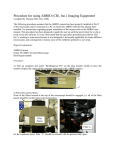
5
Figure 3. Spatial Light Modulator Components. (1) SLM optical head, (2) Optical head cable, (3) D3128
Controller, (4) USB cable, (5) Power supply, (6) PC running PixelDRIVE 3000.
3.
Turn on the front panel switch and observe the LED’s. The green power LED remains illuminated as
long as the unit is powered on. The yellow status LED blinks the D3128’s firmware version as the
D3128 control module performs a power-on self-test, then goes off. During the power-on self-test,
the entire pixel array will be driven to maximum voltage for 500 ms, reduced to half-voltage for 500
ms, then reduced to zero upon completion of the power-on self-test.
4.
The first time the D3128 is powered on, Windows® will detect a new USB device upon completion of
the power-on self-test. For installation to a PC running Windows® 2000, Windows® XP or Windows
Vista®, direct Windows® to look in the USB Drivers\Win2K_XP directory on the CD. For installation
to a PC running Windows® 98SE or Windows® ME, specify the USB Drivers\Win98_ME directory.
Note: Windows® may say that the driver has not passed certification; press continue anyway. The
drivers have been extensively tested.
5.
Install the PixelDRIVE 3000 software by first placing the PixelDRIVE CD in the CD-ROM drive.
Then, wait for the PixelDRIVE menu to appear and click on the “Install PixelDRIVE …” button. If
the menu does not appear, go to “My Computer” or Windows Explorer, double click on the CD-ROM
drive, and double click on Autorun.exe in the Autorun directory.
3. Hexagonal 127-Pixel Array
Two available D3128 optical configurations are the 127-pixel hexagonal array and the 128-pixel linear array.
Both optical configurations include software that has been customized to the geometry of the pixel array. The
software that drives the hexagonal array is detailed here; please refer to Section 4 for a discussion of the
software that drives the linear array.
3.1 PixelDRIVE 3000 Software for the Hexagonal Array
The D3128 includes PixelDRIVE 3000: a user-friendly software interface for control of the spatial light
modulator. Here we detail the functions of PixelDRIVE 3000. Also included on the CD are LabVIEW™ VI’s
D3128 User’s Manual rev. 1.04
4
(compatible with National Instruments LabVIEW™ versions 6.1 or later) that end users can include in their
own development efforts.
As voltage levels are mentioned in the present context, it is important to bear in mind that we are describing the
amplitude envelope about a 2-kHz square wave. For instance, a driver signal described as “invariant” actually
refers to a square wave with a steady amplitude; the envelope is unchanging in time but the signal itself (if
measured with an oscilloscope for instance) oscillates about the zero-voltage axis. It is important to note that
the square wave is always symmetric about the zero-voltage axis. As previously mentioned, zero-offset is
critical for nematic liquid crystal cells.
Figure 4. PixelDRIVE 3000 (Hex) User Interface
PixelDRIVE 3000 provides an easily accessible user interface by which to control the pixels of the spatial light
modulator. The software grants control of the pixel array through manipulation of the individual pixels and
through spatial functions that can be applied to the pixel array as a whole. Multiple arrays, called frames, can
be configured independently of one another. A sequence of frames can be cycled, and the duration of each
frame can be specified. The software also enables temperature control and monitoring.
From here, the user interface will be considered in six sections, shown in Fig. 5. In addition to the controls and
indicators within the six sections highlighted in Fig. 5, clicking the Meadowlark Optics logo displays software
and firmware version information.
D3128 User’s Manual rev. 1.04
5
Figure 5. Sectioned PixelDRIVE 3000 (Hex) Interface. (1) Main functions, (2) Frame control, (3) Hex
pattern generation, (4) Hex pattern adjustment, (5) Temperature control, (6) Pixel control/display.
3.1.1 Main Functions
• CONFIGURE/LIVE In LIVE mode, changes made to the on-screen pixel array are immediately
relayed to the SLM hardware. In the CONFIGURE mode, changes will not be updated until either
LOAD FRAME or CYCLE FRAMES is pressed.
• LOAD FRAME Loads the current on-screen pixel array to the SLM hardware.
• CYCLE FRAMES Activates frame cycling, loading each frame in sequence to the SLM hardware
for the specified duration. When frame cycling is activated, a small window replaces the main user
interface indicating cycling progress and allowing the user to cease frame cycling.
• ONCE/REPEAT Controls whether the CYCLE FRAMES control will load the frame sequence only
once, or repeat the sequence until the user deactivates frame cycling.
• USB DEVICE # Selects among several Meadowlark Optics USB devices when several Meadowlark
Optics USB devices are connected to the PC.
• OPEN FILE Reads frame and pixel array configuration data from an ASCII text file (see Appendix
A for the file specification).
• SAVE FILE Writes the current frame and pixel array configuration to an ASCII text file (see
Appendix A for the file specification).
• RESET Performs a soft reboot of the D3128 controller and re-enumerates the USB connection.
• EXIT Quit PixelDRIVE 3000.
3.1.2 Frame Control
• FRAME SELECTOR (slider and numeric control) Selects a pixel array from the sequence and
renders it on the display.
• ADD FRAME Adds a new frame to the sequence after the current frame.
• DELETE FRAME Removes the current frame from the sequence.
• DURATION (MSEC) Specifies the duration time in milliseconds of the current frame.
• APPLY TO ALL Sets the duration time of all frames to that of the current frame.
D3128 User’s Manual rev. 1.04
6
3.1.3 Hex Frame Generation
• PIXEL Use the arrows or enter horizontal and vertical
pixel indices to change the selected pixel. Change the pixel
value to the desired level. Hint: The horizontal and vertical
indices must both be either odd or even, i.e., (0,0) and (1,1)
are valid but (0,1) is not valid.
•
UNIFORM Sets each pixel in the array to a uniform
value.
•
LINEAR Applies a linear gradient across the pixel array.
The angle specifies the direction of the gradient, the
gradient value specifies the spatial rate of variation across
the array, and the offset uniformly adjusts the pixel values.
•
POLY (r) Applies a radially-symmetric polynomial
0
1
2
3
function, up to third-order. The r , r , r , and r coefficients
can be entered. A small plot of pixel value vs. r is
displayed.
•
SINE (r) Applies a radially-symmetric sinusoidal
function. A is the 0-peak amplitude, dA is the pixel value
offset, R is the radial period, and dR is the radial offset. A
small plot of pixel value vs. r is displayed.
•
SINC (r) Applies a radially-symmetric sinc {sin(r)/r}
function. A is the 0-peak amplitude, dA is the pixel value
offset, R is the radial period, and dR is the radial offset. A
small plot of pixel value vs. r is displayed.
•
AIRY (r) Applies a radially-symmetric Airy disk function.
A is the peak amplitude, dA is the pixel value offset, W is
the width, and dR is the radial offset. A small plot of pixel
value vs. r is displayed.
•
GAUSS (r) Applies a radially-symmetric Gaussian
function. A is the peak amplitude, dA is the pixel value
offset, W is the width, and dR is the radial offset. A small
plot of pixel value vs. r is displayed.
•
RANDOM Randomly calculates a value between the
specified upper and lower limits for each pixel.
D3128 User’s Manual rev. 1.04
7
3.1.4 Hex Pattern Adjust
• OFFSET-RESCALE
o DC ADJUST is a constant value to be added to each pixel.
o RESCALE is a multiplier by which each pixel will be scaled.
o APPLY rescales and offsets the pixel array.
• ADD NOISE Adds or subtracts a random value to each pixel.
o NEG LIMIT The maximum value that would be subtracted from each pixel.
o POS LIMIT The maximum value that would be added to each pixel.
3.1.5 Temperature Control
• STATUS LED illuminates green when the SLM temperature is within ±1°C of the setpoint.
• UPDATE LED blinks when the SLM temperature is measured.
• SETPOINT (°C) Sets the desired operating temperature of the SLM.
• TEMP (°C) Shows the current measured temperature of the SLM, updated automatically at ~2 sec
intervals. Note that automatic temperature measurement is disabled when frame cycling is active.
3.1.6 On-Screen Pixel Array
• Shows the voltage settings of each pixel as a greyscale value; black corresponds to zero volts
(maximum retardance) and white corresponds to ten volts (minimum retardance).
• Clicking a pixel highlights it as the “selected pixel” with a red dot; the angle of the red dot is
indicative of the pixel value.
• Clicking and “rotating” a pixel varies its value.
• The “extra” pixel control at (x, y) = (6, 12) of the on-screen pixel array controls the large test pixel.
3.2 The Indexing Convention of the Hexagonal Pixel Array
The on-screen pixel array locates pixels in the SLM by (x, y) coordinate indices. Fig, 7 shows the coordinate
system, and illustrates the restriction that valid coordinate pairs must be (odd, odd) or (even, even). Fig. 6
shows highlighted pixels at (x, y) = (0, 0) and at (x, y) = (1, 3) as examples of valid pixel index coordinate
pairs. A counterexample at (x, y) = (3, 6) shows an invalid coordinate pair. Fig. 6 also shows the index limits
of −6 ≤ x ≤ 6 and −12 ≤ y ≤ 12.
Figure 6. Hexagonal Pixel Array Indexing. Valid pixel coordinate indices are exemplified at (x, y) = (0, 0)
and (1, 3), while an invalid pixel coordinate pair is exemplified at (x, y) = (3, 6).
D3128 User’s Manual rev. 1.04
8
The pixel indexing convention results in a 3 :1 geometric aspect ratio, as shown in Fig. 7. In order to adapt
an analytical function of x and y, the y variables appearing in the analytical form must be divided by 3 (or x
variables must be multiplied by 3 ) to achieve proper symmetric rendering on the pixel array.
Figure 7. Pixel Indexing Aspect Ratio.
4. Linear 128-Pixel Array
Two available D3128 optical configurations are the 127-pixel hexagonal array and the 128-pixel linear array.
Both optical configurations include software that has been customized to the geometry of the pixel array. The
software that drives the linear array is detailed here; please refer to Section 3 for a discussion of the software
that drives the linear array.
4.1 PixelDRIVE 3000 Software for the Linear Array
The D3128 includes PixelDRIVE 3000: a user-friendly software interface for control of the spatial light
modulator. Here we detail the functions of PixelDRIVE 3000. Also included on the CD are LabVIEW™ VI’s
(compatible with National Instruments LabVIEW™ versions 6.1 or later) that end users can include in their
own development efforts.
As voltage levels are mentioned in the present context, it is important to bear in mind that we are describing the
amplitude envelope about a 2-kHz square wave. For instance, a driver signal described as “invariant” actually
refers to a square wave with a steady amplitude; the envelope is unchanging in time but the signal itself (if
measured with an oscilloscope for instance) oscillates about the zero-voltage axis. It is important to note that
the square wave is always symmetric about the zero-voltage axis. As previously mentioned, zero-offset is
critical for nematic liquid crystal cells.
D3128 User’s Manual rev. 1.04
9
Figure 8. PixelDRIVE 3000 (Linear) User Interface
PixelDRIVE 3000 provides an easily accessible user interface by which to control the pixels of the spatial light
modulator. The software grants control of the pixel array through manipulation of the individual pixels and
through spatial functions that can be applied to the pixel array as a whole. Multiple arrays, called frames, can
be configured independently of one another. A sequence of frames can be cycled, and the duration of each
frame can be specified. The software also enables temperature control and monitoring.
From here, the user interface will be considered in seven sections, shown in Fig. 9. In addition to the controls
and indicators within the six sections highlighted in Fig. 9, clicking the Meadowlark Optics logo displays
software and firmware version information.
D3128 User’s Manual rev. 1.04
10
Figure 9. Sectioned PixelDRIVE 3000 (Linear) Interface. (1) Main functions, (2) Frame control, (3) Pixel
control/display, (4) Temperature control, (5) Single-pixel select/control, (6) Linear pattern generation, (7)
Linear pattern adjustment.
4.1.1 Main Functions
• USB DEVICE # Selects among several Meadowlark Optics USB devices when several Meadowlark
Optics USB devices are connected to the PC.
• CONFIGURE/LIVE In LIVE mode, changes made to the on-screen pixel array are immediately
relayed to the SLM hardware. In the CONFIGURE mode, changes will not be updated until either
LOAD FRAME or CYCLE FRAMES is pressed.
• LOAD FRAME Loads the current on-screen pixel array to the SLM hardware.
• CYCLE FRAMES Activates frame cycling, loading each frame in sequence to the SLM hardware
for the specified duration. When frame cycling is activated, a small window replaces the main user
interface indicating cycling progress and allowing the user to cease frame cycling.
• ONCE/REPEAT Controls whether the CYCLE FRAMES control will load the frame sequence only
once, or repeat the sequence until the user deactivates frame cycling.
• PATTERN DEFAULTS Resets the default values for the selected pixel pattern (see Section 4.1.6
for a discussion of pattern generation).
• OPEN FILE Reads frame and pixel array configuration data from an ASCII text file (see Appendix
A for the file specification).
• SAVE FILE Writes the current frame and pixel array configuration to an ASCII text file (see
Appendix A for the file specification).
• RESET Performs a soft reboot of the D3128 controller and re-enumerates the USB connection.
• EXIT Quit PixelDRIVE 3000.
4.1.2 Frame Control
• FRAME SELECTOR (slider and numeric control) Selects a pixel array from the sequence and
renders it on the display.
• ADD FRAME Adds a new frame to the sequence after the current frame.
• DELETE FRAME Removes the current frame from the sequence.
• DURATION (MSEC) Specifies the duration time in milliseconds of the current frame.
• APPLY TO ALL Sets the duration time of all frames to that of the current frame.
D3128 User’s Manual rev. 1.04
11
4.1.3 On-Screen Pixel Array
• Shows graphically the voltage settings of each pixel (vertical) vs. the pixel index number (horizontal).
• Clicking a pixel highlights it yellow as the “selected pixel”.
• Clicking and “sliding” a pixel vertically varies its value.
4.1.4 Temperature Control
• STATUS LED illuminates green when the SLM temperature is within ±1°C of the setpoint.
• UPDATE LED blinks when the SLM temperature is measured.
• SETPOINT (°C) Sets the desired operating temperature of the SLM.
• TEMP (°C) Shows the current measured temperature of the SLM, updated automatically at ~5 sec
intervals. Note that automatic temperature measurement is disabled when frame cycling is active.
4.1.5 Single-Pixel Select/Control
• Includes pixel select and pixel level controls to precisely set the voltage of a specific pixel.
• The selected pixel is highlighted yellow in the On-Screen Pixel Array
• Changes to the voltage will be rendered in the On-Screen Pixel Array.
• Selecting or changing the voltage of a pixel by clicking the On-Screen Pixel Array will update these
controls.
4.1.6 Pattern Generation
• CONSTANT Sets each pixel in the array to a uniform value
• LINEAR The voltages will vary linearly across the array from the voltage of pixel 1 to the voltage of
pixel 128.
• PARABOLA Varies the voltage quadratically across the array.
o NEG/POS Specifies whether the parabolic voltage function will open “down” or “up”.
o MAGNITUDE Scales the parabolic voltage function.
o HORIZONTAL Shifts the parabolic voltage function left or right.
o VERTICAL Applies a DC offset to the parabolic voltage function
• SINUSOID Varies the voltage sinusoidally across the array.
O AMPLITUDE The zero-to-peak amplitude of the sinusoidal voltage function.
O CYCLES The number of sinusoidal cycles across the pixel array.
O VERTICAL The DC-offset of the sinusoidal voltage function.
O PHASE Horizontal shift of the sinusoidal voltage function.
• RANDOM Randomly calculates a value between the specified upper and lower limits for each pixel.
4.1.7 Pattern Adjustment
• OFFSET
o HORIZONTAL Shifts the pixel pattern left or right. Pixels at the ends “wrap” as they are
shifted.
o VERTICAL Applies a DC offset to the array pattern.
o APPLY Adjusts the pixel array by the specified vertical and horizontal amounts.
• SCALE
o MULTIPLIER A factor by which each pixel will be scaled.
o APPLY Rescales the pixel array.
• NOISE
o NEGATIVE The maximum value that would be subtracted from each pixel.
o POSITIVE The maximum value that would be added to each pixel.
• APPLY Adjusts each pixel by a random amount bounded by the Negative and Positive limits.
D3128 User’s Manual rev. 1.04
12
5. User Development with LabVIEW™ VI’s Provided by Meadowlark Optics, Inc.
Several VI’s are included in a library file on the PixelDRIVE 3000 CD. They can be found in <drive
letter>:\LabVIEW\ directory. LabVIEW™ VI’s that interface with the D3128 are:
• Meadowlark Hex SLM User Example.VI
• Meadowlark Linear SLM User Example.VI
• Meadowlark Hex SLM User VI’s.LLB
o Meadowlark Load Hex Array.VI
o Meadowlark Load Linear Array.VI
o Meadowlark USB Com.VI
o Meadowlark USB Easy Close.VI
o Meadowlark USB Easy Open.VI
o Meadowlark USB Read Temperature.VI
o Meadowlark USB Set Temperature.VI
The user development directory includes a LabVIEW™ library file containing fundamental VI’s and examples
that implement them in rudimentary programs that set the hexagonal and linear voltage arrays. The
LabVIEW™ back panels of the hex and linear example VI’s have been made accessible to our customers to
facilitate independent development. Developers are encouraged to open and examine the example VI diagram
screens. Please note that the LabVIEW™ development suite (version 6.1 or greater) from National
Instruments is required to use the included VI’s, and Meadowlark Optics, Inc. does not provide this
development package with PixelDRIVE 3000. It is assumed that the customer has experience programming in
LabVIEW™ and understands good programming practices. Meadowlark Optics, Inc. cannot offer customer
support for LabVIEW™ application development. If a developed or modified LabVIEW™ application is to be
distributed in any way, please contact Meadowlark Optics for licensing and copyright details.
6. Care and Maintenance of the SLM Optics
The D3128 Spatial Light Modulator is a precision instrument and should be treated accordingly. It is
especially important to observe good optics laboratory practices with the optical head. Do not allow the optics
components to become soiled, and avoid excessive unnecessary cleanings. If cleaning is required, the dropand-swab method is recommended. Wear finger cots or gloves and use lint-free optics tissue. Laboratorygrade methanol is recommended, and then only in evaporative amounts (i.e., use one drop; do not “douse” the
optics). Laboratory-grade acetone can be used only if deemed absolutely necessary, and again only in
evaporative amounts. Never use water-based cleaning solutions, never use methyl ethyl ketone (MKE) or
other solvents, never immerse the optical head or saturate the optics with solvent, and never scrub or brush the
SLM optics.
7. Frequently Asked Questions
Q: The controller is not working.
A: Check that the power supply is plugged in, front panel switch is on and the green power light is steady.
Check the status of the D3128 under Windows® Device Manager. Occasionally it helps to reboot the
controller: turn off the controller, wait a few seconds, then turn it back on. Then click the RESET button
on the PixelDRIVE 3000 user interface.
Q: Why might the SLM “pause” or “freeze” when I run very fast frame updates (frame durations ~10 ms)?
A: High-speed frame cycling can experience software conflicts with other USB devices, network activity, and
other applications (e.g., anti-virus software). If the system hangs during high-speed frame cycling, it is
recommended that the host PC be removed from any network, that all other applications be closed, and
that any other peripheral devices (especially those connected to USB ports) be removed.
Q: Are there Apple, Linux, OS/2, or UNIX versions of PixelDRIVE 3000? Can I use PixelDRIVE 3000 on a
PC running MS-DOS®, Windows® 3.1, Windows® 95, or Windows® NT?
A: No. PixelDRIVE 3000 runs under the 98SE, ME, 2000 and XP versions of Microsoft® Windows® only.
D3128 User’s Manual rev. 1.04
13
Q: Can I write a program in C, FORTRAN, or Pascal that will talk to the D3128?
A: Meadowlark Optics, Inc. presently supports only LabVIEW™ software development for the D3128.
Future releases might include development resources for alternative programming platforms.
Q: What is the purpose of the SYNC and TRIGGER connectors on the front panel?
A: The TRIGGER connector generates an output pulse coinciding with any update to the pixel array. This
signal can be used to synchronize external devices to the D2138. The SYNC connector is not presently
active; it is reserved for future applications.
Q: What are valid (x, y) pixel indices for the hexagonal array?
A: Pixel indices must occur as (odd, odd) or (even, even) pairings. For example, (0, 0) and (1, 1) are valid
pixel indices, but (0, 1) is invalid. Horizontal index boundaries are −6 ≤ x ≤ 6. Vertical index boundaries
are −12 ≤ y ≤ 12.
Q: I calculated a frame of pixel values for the hexagonal array using a spreadsheet and a formula f(x, y).
When I loaded the frame into PixelDRIVE 3000, the function was distorted, appearing stretched vertically
or horizontally. What happened?
A: The aspect ratio of the indexing convention (the x and y coordinates of the pixels) is 1: 3 , not 1:1.
When calculating pixel values, use f ( x ⋅ 3, y ) or f ( x, y 3) .
Q: What are the power-on default voltage and temperature values?
A: After powering on the D3128, the array will be driven to 10 volts for 500 ms, switched to 5 volts for 500
ms, then switched to zero volts. Upon completion of the power-on voltage cycle, the USB connection to
the PC will be established. The temperature setpoint initializes to 35°C.
Q: What is the purpose of the “extra” pixel control in the hexagonal pixel array?
A: This controls the “test pixel” which is a large, uniformly-driven region of the SLM optic outside of the
patterned hexagonal pixel array.
Meadowlark Optics, Incorporated
P.O. Box 1000, Frederick, Colorado 80530
303-833-4333
www.meadowlark.com
[email protected]
D3128 User’s Manual rev. 1.04
14
Appendix A. Pixel Data File Formats
PixelDRIVE 3000 offers a feature for saving and loading pixel configurations as ASCII-text data files. The
first row of a Pixel data file is a space-delimited header line that includes the type of SLM, PixelDRIVE 3000
software version number, D3128 firmware version number, number of frames, number of pixels, and the date
and time the file was generated. When a pixel data file is opened with PixelDRIVE 3000, the SLM identifier
must match the hardware configuration of the SLM (e.g., “Hex” for the Hex SLM and “Linear” for the Linear
SLM). The remainder of the file includes tab-delimited columns of pixel values that differ depending on the
type of SLM (hexagonal or linear).
A.1 File Format for the Hexagonal Array SLM
The second row is tab-delimited and contains header characters x and y, followed by frame duration times (in
seconds). The 128 remaining rows are tab-delimited and consist of x-pixel indices, y-pixel indices, and pixel
values. The file format is illustrated in Fig. 10.
Each row must contain data for a unique pixel, i.e., the (x, y) indices of each row must not be repeated in a
different row. For hexagonal SLM data files, the order in which the pixels appear is not important (they will
be sorted by the (x, y) coordinates when PixelDRIVE 3000 reads the file). Columns represent frames and must
be tab-delimited, and the PixelDRIVE 3000 frame sequence order is determined by the order in which columns
appear in the data file.
A voltage “surface” function V(x, y) can be evaluated to produce pixel values. In calculating analytical
functions, it should be noted that the pixel indexing convention results in a 3 :1 aspect ratio. In other words,
in order to adapt an analytical function of x and y, the y variables appearing in the analytical form must be
divided by 3 (or x variables must be multiplied by 3 ) to achieve proper symmetric rendering on the pixel
array.
Figure 10. PixelDRIVE 3000 ASCII Data File Format (Hexagonal Array). One header row, one row of
frame durations, and 128 rows of pixel data. Two columns of (x, y) coordinates, the remaining columns denote
frames of pixel data.
D3128 User’s Manual rev. 1.04
15
A.2 File Format for the Linear Array SLM
The second row is tab-delimited and contains frame duration times (in seconds). The 128 remaining rows are
tab-delimited and consist of pixel values. Pixel values are sorted in ascending pixel-order. Columns represent
frames and must be tab-delimited, and the PixelDRIVE 3000 frame sequence order is determined by the order
in which columns appear in the data file. The file format is illustrated in Fig. 11.
A voltage vs. x function V(x) can be evaluated to produce pixel values. In generating a list of pixel voltages,
voltage values must be sorted as x varies from 1 to 128.
Figure 11. PixelDRIVE 3000 ASCII Data File Format (Linear Array). One header row, one row of frame
durations, and 128 rows of pixel data. Each column denotes a frame of pixel data.
D3128 User’s Manual rev. 1.04
16
Appendix B: Firmware Updater
The D3128 internal firmware can be reprogrammed by the user when new versions are released by Meadowlark Optics.
Update is accomplished by using the firmware updater program included on the PixelDRIVE CD. In order to use the
firmware updater program the D3128 must be powered on and connected to an available USB port on the host computer.
Perform the following steps to reprogram the D3128 firmware:
1.
Install the firmware updater software on a PC running Microsoft® Windows® (98SE or later). Place the included
CD in the CD-ROM drive, open the “Firmware updater” folder and double-click “setup.exe”.
2.
Start the firmware updater software by clicking Start|Programs|Meadowlark Optics/Firmware updater. The
following screen will appear:
3.
Cycle power on the D3128 controller to ensure the USB connection is properly made. After the front panel status
LED is done flashing, wait at least 2 seconds before clicking OK. If the power is not cycled or the OK button is
clicked too soon, the following error will be displayed. If this error appears, close the firmware updater program
and re-run it.
D3128 User’s Manual rev. 1.04
17
4.
The following screen will appear after the USB connection is made.
5.
Choose the new hex file and click “OK”. The program will check if the new firmware file is valid for the
D3128, if not, the following error screen will appear. At this point the user may elect to choose a different file or
go ahead and program the D3128 with the chosen file. Extreme caution should be exercised when deciding
whether to program the D3128 with a file that may not be compatible. If there are questions about choosing the
appropriate file please contact Meadowlark Optics at 303-833-4333.
D3128 User’s Manual rev. 1.04
18
6.
After the hex file is loaded and passes the validity tests, the ready screen appears as below (Code Size shows the
size of the firmware code and is present only for troubleshooting). Click the Program button to reprogram the
D3128 firmware. If a final check is desired before reprogramming firmware the Meadowlark Optics logo may be
clicked to display a screen (shown below) showing the old and new firmware versions.
D3128 User’s Manual rev. 1.04
19
7.
As the firmware is being erased and reprogrammed the status will be displayed as shown below. DO NOT
disturb power to the D3128 while it is erasing or reprogramming, if memory is corrupted it will be required to
return the unit to Meadowlark Optics for reprogramming.
8.
After programming is complete the following screen appears. When the controller power is cycled the status
light should flash a pattern corresponding to the version number of the new firmware. The new firmware version
may also be determined by clicking the Meadowlark Optics logo in the upper left corner of PixelDRIVE.
D3128 User’s Manual rev. 1.04
20
Appendix C. Software Licensing
IMPORTANT. CAREFULLY READ THE TERMS AND CONDITIONS OF THIS LICENSE
AGREEMENT BEFORE USING THIS SOFTWARE. This Meadowlark Optics, Inc. License
Agreement is a legal agreement between you (“Licensee”) and Meadowlark Optics, Inc. (“Licensor”) for
the enclosed computer software, and any associated media, printed materials and online or electronic
documentation (“Software”). By installing or otherwise using the Software Product, you agree to be
bound by the terms of this License Agreement. If you do not agree to the terms of this License
Agreement, do not use or install the Software Product, you may however return it to your place of
purchase for a refund.
SOFTWARE LICENSE AGREEMENT
This Software License Agreement (“Agreement”) is entered into between Meadowlark Optics, Inc
(“Licensor”) and you as Licensee, (Licensee”).
1.
Definitions
a. Software. The term “Software” shall mean the enclosed computer software, and any associated
media, printed materials and online or electronic documentation. The term “Software” includes
any corrections, bugs, fixes, enhancements, updates or other modifications, including custom
modifications, to such computer programs.
2.
License
a. Grant of License. Licensor grants Licensee, pursuant to the terms and conditions of this
Agreement, a limited, revocable, non-exclusive, non-transferable license to use the Software,
which has been built with National Instruments LabVIEW™ Application Builder.
3.
b.
Restrictions on Use. Licensee agrees to use the Software only for Licensee’s own business.
Licensee shall not: (i) permit any parent, subsidiaries, affiliated entities or third parties to use the
Software; (ii) process or permit to be processed the data of any other party, (iii) use the Software
in the operation of a service bureau, or (iv) allow access to the Software through any terminals
located outside of Licensee’s Site.
c.
Copies. Licensee, solely to enable it to use the Software, may make one archival copy of the
Software computer program, provided that the copy shall include Licensor’s copyright and any
other propriety notices. The Software delivered by Licensor to Licensee and the archival copy
shall be stored at Licensee’s Site.
d.
Modifications, Reverse Engineering. Licensee agrees that only Licensor shall have the right to
alter, maintain, enhance or otherwise modify the Software. Licensee shall not disassemble,
decompile or reverse engineer the Software.
e.
Material Terms and Conditions. Licensee specifically agrees that the terms and Conditions of
this Section 2 are material and that failure of Licensee to comply with these terms and conditions
shall constitute sufficient cause to terminate this Agreement.
Data Conversion, Support
a. Data Conversion. Licensee shall be solely responsible for data conversion, data entry and
verification of data.
b.
Support. Licensor may provide Licensee with support services related to the Software. Use of
Support services is governed by the Licensor policies and programs described in the Service
Level Agreement. Any supplemental software code, modifications or enhancements provided to
D3128 User’s Manual rev. 1.04
21
you as part of the Support service shall be considered part of the Software and subject to the
terms of this License Agreement.
4.
Ownership
a. Title. Licensee and Licensor agree that Licensor owns all proprietary rights, including patent,
copyright, trade secret, trademark and other proprietary rights, in and to the Software and any
bug fixes, enhancements, updates or other modifications, including custom modifications, to the
Software, whether made by Licensor or any third party.
b.
5.
Limited Warranty; Support Services
a. Scope of Warranty. Licensor warrants for a period of one year from the date of receipt of the
Software against faulty workmanship or the use of defective materials and that such Software
will conform to Licensor’s accompanying written specifications. This limited warranty shall be
void in the event of failure from accident, abuse or misapplication.
b.
6.
Transfers. Under no circumstances shall Licensee sell, license, publish display, distribute or
otherwise transfer to a third party the Software or any copy thereof, in whole or in part, without
Licensor’s prior written consent.
Disclaimer of Any Other Warranty. THE LIMITED WARRANTY SET FORTH IN
SUBSECTION 5.a IS IN LIEU OF ALL OTHER WARRANTIES, INCLUDING, BUT NOT
LIMITED TO, THE IMPLIED WARRANTIES OF MERCHANTABILITY AND FITNESS
FOR A PARTICULAR PURPOSE.
No Consequential Damages
NEITHER PARTY SHALL BE LIABLE TO THE OTHER FOR INDIRECT, SPECIAL,
INCIDENTAL, EXEMPLARY OR CONSEQUENTIAL DAMAGES (INCLUDING,
WITHOUT LIMITATION, LOST PROFITS) RELATED TO THIS AGREEMENT OR
RESULTING FROM LICENSEE’S USE OR INABILITY TO USE THE SOFTWARE,
ARISING FROM ANY CAUSE OF ACTION WHATSOEVER, INCLUDING CONTRACT,
WARRANTY, STRICT LIABILITY OR NEGLIGENCE, EVEN IF THAT PARTY HAS
BEEN ADVISED OF THE POSSIBILITY OF SUCH DAMAGES.
7.
Limitation on Recovery
Under no circumstances shall the liability of Licensor to Licensee exceed the amounts paid by
Licensee to Licensor under this Agreement.
8.
Indemnity
Licensor shall indemnify and hold harmless Licensee from and against any claims based on
infringement of any United States copyright or patent by the Software. Licensee agrees to cooperate
fully with Licensor during such proceedings. Licensor shall defend and settle at its sole expense all
proceedings arising out of the foregoing. In the event of such infringement, Licensor may replace, in
whole or in part, the Software with a substantially equivalent computer program or modify the
Software to avoid the infringement.
9.
Term and Termination
a. Term. This license agreement is effective from the date of receipt of this agreement and shall
remain in full force until terminated. Without prejudice to any other right, Licensor may
terminate this agreement if you fail to comply with any of the terms and conditions of this license
agreement.
b.
Procedure upon Termination. Within ten (10) days after termination of this Agreement, Licensee
will return to Licensor, at Licensee’s expense, the Software and all copies thereof, delete or
destroy all other copies of the Software, and deliver to Licensor a certification, signed by an
D3128 User’s Manual rev. 1.04
22
officer of Licensee, that the Software has been returned, all copies deleted or destroyed, and its
use discontinued.
10.
Force Majeure
If performance hereunder (other than payment) is interfered with by any condition beyond a party’s
reasonable control, including any Act of God, the affected party shall be excused from such
performance to the extent of such condition. However, if a force majeure detrimentally affects a
party’s performance of a material obligation hereunder for 14 days or more, the other party can
terminate this Agreement.
11.
Mediation, Arbitration
The parties shall endeavor to resolve any dispute by mediation in Boulder, CO under the CPR
Mediation Procedure. If the parties have not resolved this matter within 45 days from the selection of
a mediator, the parties shall settle any controversy arising out of this Agreement) by arbitration to be
held in Boulder, Colorado, in accordance with the rules of the American Arbitration Association. A
single arbitrator shall be agree upon by the parties, or, if the parties cannot agree upon an arbitrator
within thirty (30) days, then the parties agree that a single arbitrator shall be appointed by the
American Arbitration Association. The arbitrator will apply the substantive law of the State of
Colorado. The arbitrator may award attorney’s fees and costs as part of the award. The award of the
arbitrator shall be binding and may be entered as a judgment in any court of competent jurisdiction.
12.
Notices
Any notice under this Agreement will be in writing and delivered by personal delivery, overnight
courier, confirmed facsimile, confirmed e-mail, or certified or registered mail, return receipt
requested, and will be deemed given upon personal delivery, 1 day after deposit with an overnight
courier, 5 days after deposit in the mail, or upon confirmation of receipt of facsimile or email. Notices
will be sent to a party at its address set forth at the end of this Agreement, or such other address as a
party may specify in writing pursuant to this Section.
13.
Entire Agreement; Amendment; Waiver
This Agreement sets forth the entire understanding and agreement of the parties, and supersedes any
and all oral or written agreements or understandings between the parties, as to the subject matter of
the Agreement. This Agreement may be changed only by a writing signed by both parties. The waiver
of a breach of any provision of this Agreement will not operate or be interpreted as a waiver of any
other or subsequent breach.
14.
Severability; Headings
If any provision herein is held to be invalid or unenforceable for any reason, the remaining provisions
will continue in full force without being impaired or invalidated in any way. The parties agree to
replace any invalid provision with a valid provision that most closely approximates the intent and
economic effect of the invalid provision. Headings are for reference purposes only and in no way
define, limit, construe or describe the scope or extent of such section.
15.
Governing Law
This Agreement will be governed and construed in accordance with the laws of the State of Colorado
without giving effect to conflict of laws principles. Both parties submit to personal jurisdiction in
Colorado.
Trademarks
National Instruments, LabVIEW, and NI-VISA are trademarks of National Instruments Corporation.
Microsoft®, Windows®, and MS-DOS ® are registered trademarks of Microsoft Corporation.
Pentium® is a registered trademark of Intel Corporation.
All other copyrights cited in this document are the property of their respective owners.
D3128 User’s Manual rev. 1.04
23