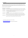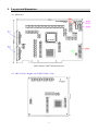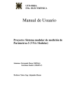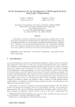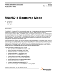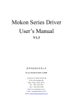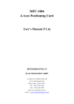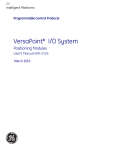
1
MPC3024A/AC 4-Axis Motion Control Card User’s Manual (V1.2) 健昇科技股份有限公司 JS AUTOMATION CORP. 新北市汐止區中興路 100 號 6 樓 6F., No.100, Zhongxing Rd., Xizhi Dist., New Taipei City, Taiwan TEL:+886-2-2647-6936 FAX:+886-2-2647-6940 http://www.automation.com.tw http://www.automation-js.com/ E-mail:[email protected] Correction record Version 1.0 Record MPC3024A compatible with old version MPC3024 MPC3024AC with new function of pulse referenced PI closed loop control 1.0->1.1 Modify 2. Feature-Delete Software key function 1.1->1.2 Add 3.2.5 Differential (pulse) output capacity 1 Contents 1. 2. Forward ............................................................................................................................................... 5 Features ............................................................................................................................................... 6 2.1 Main card .................................................................................................................................. 6 2.2 Daughter card (MPC3024AC only) .......................................................................................... 6 2.3 Din rail mounted wiring board.................................................................................................. 6 3. Specifications ...................................................................................................................................... 7 3.1 MPC3024A/AC Main card ....................................................................................................... 7 3.2 Din rail mounted wiring board.................................................................................................. 8 4. Layout and dimension......................................................................................................................... 9 4.1 Main card .................................................................................................................................. 9 4.2 MPC3024AC daughter card (MPC3024AC only) .................................................................... 9 4.3 MPC3024AC piggy back layout and dimension (MPC3024AC only)................................... 10 4.4 Din rail mounted wiring board for JF1,JF2 .............................................................................11 4.5 JS51050 for JM3 25PM Din rail mounted dummy wiring board ........................................... 12 5. Pin definitions ................................................................................................................................... 13 5.1 JF1,JF2 Assignment / Definitions ........................................................................................... 13 5.2 JM1,JM2 Assignment / Definitions ........................................................................................ 15 5.3 JM3 Assignment / Definitions ................................................................................................ 15 6. I/O interface diagram ........................................................................................................................ 16 6.1 JF1/2 ADP3024ACDIN, ADP3024DIN ................................................................................. 16 6.2 JM3 JS51050........................................................................................................................... 19 7. External wiring diagram ................................................................................................................... 20 8. Hardware settings ............................................................................................................................. 22 8.1 Card ID setting ........................................................................................................................ 22 8.2 Polarity setting for over-travel limit switch ............................................................................ 22 8.3 JP1 Jumper setting .................................................................................................................. 22 9. Applications ...................................................................................................................................... 23 10. Wiring diagram examples (pulse mode control) ............................................................................... 24 10.1 The wiring diagram for MPC3024A/AC wiring board to panasonic MINAS-A driver ......... 24 10.2 The wiring diagram for MPC3024A/AC wiring board to panasonic MINAS MSD*** driver 24 10.3 The wiring diagram for MPC3024A/AC wiring board to ESD servo driver.......................... 25 10.4 The wiring diagram for MPC3024A/AC wiring board to Moda servo driver ........................ 25 10.5 The wiring diagram for MPC3024A/AC wiring board to YASKAWA servo driver .............. 26 10.6 The wiring diagram for MPC3024A/AC wiring board to Mokon / YPV servo driver ........... 26 10.7 The wiring diagram for MPC3024A/AC wiring board to Mokon / YJD servo driver ........... 27 10.8 The wiring diagram for MPC3024A/AC wiring board to MITSUBISHI J2-SUPER servo driver 28 10.9 The wiring diagram for MPC3024A/AC wiring board to YAMAHA SRCP servo driver ..... 28 2 10.10 The wiring diagram for MPC3024A/AC wiring board to Delta ASDA-B servo driver ......... 29 11. Wiring diagram examples (fully closed loop control) ...................................................................... 30 11.1 The wiring diagram for MPC3024AC wiring board to Mokon / YPV servo driver............... 30 11.2 The wiring diagram for MPC3024AC wiring board to Mokon / YJD servo driver ............... 31 11.3 The wiring diagram for MPC3024AC wiring board to ESD servo driver.............................. 32 11.4 The wiring diagram for MPC3024AC wiring board to Moda servo driver ............................ 33 11.5 The wiring diagram for MPC3024AC wiring board to YASKAWA servo driver .................. 34 11.6 The wiring diagram for MPC3024AC wiring board to MITSUBISHI J2-SUPER servo driver 35 11.7 The wiring diagram for MPC3024AC wiring board to Delta ASDA-B servo driver ............. 36 12. Ordering information ........................................................................................................................ 37 3 Notes on hardware installation Please follow step by step as you are installing the control cards. 1. Be sure your system is power off. 2. Be sure your external power supply for the wiring board is power off. 3. Plug your control card in slot, and make sure the golden fingers are put in right contacts. 4. Fasten the screw to fix the card. 5. Connect the cable between the card and wiring board. 6. Connect the external power supply for the wiring board. 7. Recheck everything is OK before system power on. 8. External power on. Congratulation! You have it. For more detail of step by step installation guide, please refer the file “installation.pdf “ on the CD come with the product or register as a member of our user’s club at: http://automation.com.tw/ to download the complementary documents. 4 1. Forward Thank you for your selection of 4 axis motion control card. This card adopt the ASIC chip with complex motion functions including point to point, linear and circular interpolation, linear and s-curve acceleration/deceleration and several miscellaneous functions. Dll’s of various functions will save you a lot of time in the motion related projects. Our other motion control products: MPC3028A 8 axes linear/circular/point to point (standard function) motion control card (PCI bus) MPC3034A 4 axes linear/circular/point to point (advanced function) motion control card (PCI bus) MPC3042A 2 axes linear/circular/point to point (standard function) motion control card with Pulse Referenced PI Control (PCI bus) MPC3042AL 2 axes linear/circular/point to point (standard function) motion control card (PCI bus) MPC3035A 4 axes linear/circular/point to point (standard function) motion control card with advanced encoder counter function / with 2 8bit DA’s motion control card (PCI bus) MPC3035AL 4 axes linear/circular/point to point (standard function) motion control card with advanced encoder counter function motion control card (PCI bus) Any comment is welcome, please visit our website http://www.automation.com.tw/ http://www.automation-js.com/ for the up to date information. 5 2. Features 2.1 Main card 2.1.1 4-axis servo/stepping motor control 2.1.2 4 28-bit up/down counter for incremental encoder 2.1.3 4 28-bit up/down counter for pulse handler input 2.1.4 Pulse output rate up to 6.55MHz 2.1.5 Pulse output options : OUT/DIR,CW/CCW 2.1.6 2~4 axes linear interpolation 2.1.7 Any 2 axes circular interpolation 2.1.8 S curve or T curve acceleration / deceleration in interpolation and positioning 2.1.9 Continuous interpolation 2.1.10 Speed change on the fly 2.1.11 Synchronized start motion 2.1.12 Position latch function 2.1.13 Simultaneously start/stop on multi-axes 2.1.14 Programmable interrupt conditions 2.1.15 Backlash compensation 2.1.16 Pulse handler function 2.1.17 Software limit switches protection 2.1.18 2 nibble configurable digital TTL I/O 2.1.19 Motion parameters change on the fly 2.2 Daughter card (MPC3024AC only) 2.2.1 4-axis servo fully closed loop PI control 2.2.2 4 stepper semi-closed loop control 2.2.3 Mixed semi-closed / fully closed loop control 2.2.4 Tracking control on X, Y and Z, A axis 2.2.5 Encoder feedback broken detection 2.2.6 4 17-bit DA 2.3 Din rail mounted wiring board 2.3.1 JS51050 dummy wiring board for JM3 pulse handler interface 2.3.2 ADP3024ACDIN wiring board for JF1,2 motion control interface 6 3. Specifications 3.1 MPC3024A/AC Main card Motion 3.1.1 3.1.2 3.1.3 3.1.4 3.1.5 3.1.6 3.1.7 3.1.8 3.1.9 Max pulse rate ─ 6,553,500 pps Pulse output mode ─ Single phase: CLOCK,DIR Dual phase ─ CW, CCW Acceleration / Deceleration mode ─ linear ,S-curve mode Homing mode ─ 14 types Encoder up/down counter ─ 4 28bit counter Pulse Handle up/down counter ─ 4 28 bit counter Linear interpolation ─ any 2 up to 4 axis Circular interpolation ─ any 2 axes Pulse referenced PI closed loop control (MPC3024AC only) 3.1.10 Resolution ─ 17-bit 3.1.11 D/A range ─ +10Vdc ~ -10Vdc 3.1.12 Error counter ─ 32-bit 3.1.13 Digital sample time ─ 0.25ms 3.1.14 Proportional gain ─ 1~4095 3.1.15 Integral time ─ 1ms ~ 4095ms 3.1.16 Feedback multiple rate ─ x1, x2, x4 Digital I/O 3.1.17 Motion specific input ─ SRDY, ALM, LS+(EL+), LS-(EL-), SD, HOME(ORG), 3.1.18 3.1.19 3.1.20 PCS, LTC per axis , EMG per card Motion specific output ─ CMP,SVON,ERC,FIN per axis General input ─ INP per axis TTL I/O ─ 2 nibble configurable TTL I/O General 3.1.21 3.1.22 3.1.23 3.1.24 3.1.25 3.1.26 3.1.27 3.1.28 3.1.29 Card ID ─ 16 locations set by rotary switch Insulation resistance ─ 100 MΩ (min) at 1000Vdc Isolation voltage ─ 2500Vac 1Min I/O connector ─ 2 68pin female mini SCSI connector External supply ─ DC 24±4V Operation temperature ─ 0 to 70° C Storage temperature ─ -20 to 80° C Operation humidity ─ 5~95% RH, non-condensing Dimensions ─ 175(W) * 122(H) mm , 6.9(W)*4.8(H)in 7 3.2 Din rail mounted wiring board ADP3024ACDIN for JF1,2 motion control interface 3.2.1 Power Requirement ─ 24Vdc ± 4Vdc 3.2.2 On Board Build-in s.p.s. ─ +5Vdc 500mA (max) 3.2.3 General input ─ 4 with LED indicator 3.2.4 Output capacity ─ 8 NMOS output, 1A continuous、120Vdc(max) Option : 8 PMOS output, 1A continuous、24Vdc(max) Option : 8 Relay output, 3A continuous、250Vac(max) 3.2.5 Differential (pulse) output capacity ─ 20ma(max), Voh>2.5V, Vol<0.5V 3.2.6 Connector ─ 2 68pin mini SCSI female connector for main card connection 3.2.7 Specific servo control connectors ─ 4 D-type 26p (1 per axis) 3.2.8 Operation temperature ─ 0 to 70° C 3.2.9 Operation humidity ─ RH5~95%, non-condensed 3.2.10 Dimension ─ ADP3024ACDIN(N) : 121(W) * 204(L) *47(H)mm; 4.8(W)*8.1(L)*1.9(H)in ADP3024ACDIN(P) / (R) : 121(W) * 204(L) *45(H)mm 4.8(W)*8.1(L)*1.8(H)in JS51050 for JM3 pulse handler interface 3.2.11 Connection cable ─ D-type 25P cable to connect main and wiring board 3.2.12 Dimension ─ 86(W)*79(L)*52(H)mm , 3.4(W)*3.2(L)*2.1(H)in 8 4. Layout and dimension 4.1 Main card MPC3024AC/ MPC3024A main card 4.2 MPC3024AC daughter card (MPC3024AC only) 9 4.3 MPC3024AC piggy back layout and dimension (MPC3024AC only) 10 4.4 Din rail mounted wiring board for JF1,JF2 ADP3024ACDIN for JF1,2 (MPC3024AC only) ADP3024DIN for JF1,2 11 4.5 JS51050 for JM3 25PM Din rail mounted dummy wiring board 12 5. Pin definitions 5.1 JF1,JF2 Assignment / Definitions MPC3024AC MPC3024A 13 PIN I/O Descriptions 1 I Z/X_LS+(EL+) Positive over travel LS(EL) of Z/X axis 2 I Z/X_SD Slowdown LS(EL) of Z/X axis 3 I Z/X_PCS Position change start signal of Z/X axis 4 O Z/X_FIN General purpose output of Z/X axis 5 I Z/X_EA+ Encoder phase A+ feedback of Z/X axis 6 I Z/X_EB+ Encoder phase B+ feedback of Z/X axis 7 I Z/X_EZ+ Encoder phase Z+ feedback of Z/X axis 8 O Z/X_CW+ CW+ or PULSE+ of Z/X axis 9 O Z/X_CCW+ CCW+ or DIR+ of Z/X axis 10 I Z/X_INP General I/p of Z/X axis 11 I Z/XALM ALARM I/p of Z/X axis 12 O Z/X_ERC Output for resetting error counter of Z/X axis 13 I A/YLS-(EL-) Negative over travel LS(EL) of A/Y axis 14 I A/Y_HOME(ORG) Home(ORG) LS(EL) of A/Y axis 15 I A/Y_LTC Latch counter trigger of A/Y axis 16 O A/Y_CMP General out or compare out of A/Y axis 17 I A/Y_EAEncoder phase A- feedback of A/Y axis 18 I A/Y_EBEncoder phase B- feedback of A/Y axis 19 I A/Y_EZEncoder phase Z- feedback of A/Y axis 20 O A/Y_CWCW- or PULSE- of A/Y axis 21 O A/Y_CCWCCW- or DIR- of A/Y axis 22 I A/Y_SRDY Servo Ready signal of A/Y axis 23 O A/YSVON Servo on of A/Y axis 24 NC | 29 30 I EMG Emergency stop, stop all axes 31 O X/Z_DA / NC 32 EXTG Common for external power (+24V and +5V) 33 O +5V DC5V power output for external device 34 I +24V External DC24V power input PIN I/O Descriptions 35 I Z/X_LS-(EL-) Negative over travel LS(EL) of Z/X axis 36 I Z/X_HOME(ORG) Home(ORG) LS(EL) of Z/X axis 37 I Z/X_LTC Latch counter trigger of Z/X axis 38 O Z/X_CMP General out or compare out of Z/X axis 39 I Z/X_EAEncoder phase A- feedback of Z/X axis 40 I Z/X_EBEncoder phase B- feedback of Z/X axis 41 I Z/X_EZEncoder phase Z- feedback of Z/X axis 42 O Z/X_CWCW- or PULSE- of Z/X axis 43 O Z/X_CCWCCW- or DIR- of Z/X axis 44 I Z/X_SRDY Servo Ready signal of Z/X axis 45 O XSVON -- Servo on of X axis 46 I A/Y_LS+(EL+) Positive over travel LS(EL) of A/Y axis 47 I A/Y_SD Slowdown LS(EL) of A/Y axis 48 I A/Y_PCS Position change start signal of A/Y axis 49 O A/Y_FIN General purpose output of A/Y axis 50 I A/Y_EA+ Encoder phase A+ feedback of A/Y axis 51 I A/Y_EB+ Encoder phase B+ feedback of A/Y axis 52 I A/Y_EZ+ Encoder phase Z+ feedback of A/Y axis 53 O A/YCW+ CW+ or PULSE+ of A/Y axis 54 O A/Y_CCW+ CCW+ or DIR+ of A/Y axis 55 I A/Y_INP General I/p of A/Y axis 56 I A/Y_ALM ALARM I/p of A/Y axis 57 O A/Y_ERC Output for resetting error counter of A/Y axis 58 NC | 63 64 I EXTG Common for external power (+24V and +5V) 65 O Y/A_DA / NC 66 EXTG Common for external power (+24V and +5V) 67 O +5V DC5V power output for external device 68 I +24V External DC24V power input 14 5.2 JM1,JM2 Assignment / Definitions PIN Description 1 CSTA: common start I/O 2 CSTP: common stop I/O 3 GND Note: Connect CSTA low to start motion from external. Connect CSTP low to emergency stop motion from external. 5.3 JM3 Assignment / Definitions PIN 1 2 3 4 5 6 7 8 9 10 11 12 13 PIN Description +5Vout_PC +5V from PC PA1 Pulse handler1 A phase input PA2 Pulse handler2 A phase input GND 14 15 16 17 PA3 Pulse handler3 A phase input PA4 Pulse handler4 A phase input GND 18 19 20 +5Vout_PC +5V from PC IO0 TTL I/O bit0 IO 2 TTL I/O bit2 IO 4 TTL I/O bit4 IO 6 TTL I/O bit6 GND 21 22 23 24 25 15 Description +5Vout_PC +5V from PC PB1 Pulse handler1 B phase input PB2 Pulse handler2 B phase input GND PB3 Pulse handler3 B phase input PB4 Pulse handler4 B phase input GND +5Vout_PC +5V from PC IO1 TTL I/O bit1 IO 3 TTL I/O bit3 IO 5 TTL I/O bit5 IO 7 TTL I/O bit7 6. I/O interface diagram 6.1 JF1/2 ADP3024ACDIN, ADP3024DIN 6.1.1 Input diagram Type1 input: For input: LS+(EL+), LS-(EL-), HOME(ORG), SD,PCS,EMG, LTC Type2 input: For input: INP,SRDY,ALM 16 Type3 input: For encoder feedback input : A+/-,B+/-,Z/6.1.2 Output diagram Type1 output: For SVON, ERC Type2 output: FIN,CMP(NMOS) 17 Type3 output: FIN,CMP(Relay) Type4 output: FIN,CMP(PMOS) Type5 output: For motion control pulse output : CW,CCW (drive capacity <20ma, Voh>2.5V, Vol<0.5V) 18 Type6 output: Digital to analog converter (ADP3024ACDIN Only) 6.2 JM3 JS51050 Type 1 Input: For Pulse Handler Input : PA,PB Type 2 TTL I/O: For byte-programmable TTL I/O IO0 ~ IO7 to configured as pull high or pull low. JP1 are used for output state of power on. (refer 8.3 JP1 Jumper setting) 19 7. External wiring diagram MPC3024AC wiring board with NMOS output MPC3024A wiring board with NMOS output MPC3024AC wiring board with PMOS output MPC3024A wiring board with PMOS output 20 MPC3024AC Wiring board with Relay output MPC3024A Wiring board with Relay output * User may connect the signals with this DB26 specific connectors (one axis per connector) or screw terminals. Wiring board DB26 specific connector *Differential signals needs connect EXTG as common. *COM connect to power supply as free-wheel path to avoid high voltage induced by inductive load. 21 8. Hardware settings 8.1 Card ID setting Since PCI cards have plug and play function, the card ID is required for programmer to identify which card he/she will control without knowing the physical address assigned by the Windows. A 4 bits ROTARY switch (select from 0 to 0xF )for extinguishing the 16 identical card. 8.2 Polarity setting for over-travel limit switch For different applications maybe you have different considerations, the polarity of over-travel limit switch can be set by on card Dip switch to meet your requirement. Default : A, Z, Y, X axis are in negative polarity , the DIP switch set as follows. Example : A, Z axis are in negative polarity and Y, X axis polarity are positive, the DIP switch set as follows. 8.3 JP1 Jumper setting 1-2 short Pull High 2-3 short Pull Low Jumper JP1 is used for the TTL output default state, if you disable the TTL port or at computer start-up period, the default state will be output. Select the one to match with the succeeding circuit. 22 9. Applications Precision positioning control Precision speed control Contouring control X-Y table control Rotary machine control Robotic control Biotech sampling and handling Any combined control of servo and stepping motors 23 10. Wiring diagram examples (pulse mode control) Note: Be sure that your driver is set under position mode (pulse control mode) 10.1 The wiring diagram for MPC3024A/AC wiring board to panasonic MINAS-A driver 10.2 The wiring diagram for MPC3024A/AC wiring board to panasonic MINAS MSD*** driver 24 10.3 The wiring diagram for MPC3024A/AC wiring board to ESD servo driver 10.4 The wiring diagram for MPC3024A/AC wiring board to Moda servo driver 25 10.5 The wiring diagram for MPC3024A/AC wiring board to YASKAWA servo driver 10.6 The wiring diagram for MPC3024A/AC wiring board to Mokon / YPV servo driver 26 10.7 The wiring diagram for MPC3024A/AC wiring board to Mokon / YJD servo driver 27 10.8 The wiring diagram for MPC3024A/AC wiring board to MITSUBISHI J2-SUPER servo driver 10.9 The wiring diagram for MPC3024A/AC wiring board to YAMAHA SRCP servo driver 28 10.10 The wiring diagram for MPC3024A/AC wiring board to Delta ASDA-B servo driver 29 11. Wiring diagram examples (fully closed loop control) Note: Be sure that your driver is set under speed mode (analog voltage control mode) 11.1 The wiring diagram for MPC3024AC wiring board to Mokon / YPV servo driver 30 11.2 The wiring diagram for MPC3024AC wiring board to Mokon / YJD servo driver 31 11.3 The wiring diagram for MPC3024AC wiring board to ESD servo driver 32 11.4 The wiring diagram for MPC3024AC wiring board to Moda servo driver 33 11.5 The wiring diagram for MPC3024AC wiring board to YASKAWA servo driver 34 11.6 The wiring diagram for MPC3024AC wiring board to MITSUBISHI J2-SUPER servo driver 35 11.7 The wiring diagram for MPC3024AC wiring board to Delta ASDA-B servo driver 36 12. Ordering information PRODUCT MPC3024AC DESCRIPTIONS 4-axis motion control card for servo/step motor control with Pulse referenced PI closed loop control ADP3024ACDIN(N) DIN rail mounted wiring board matched MPC3024AC, General output: 8 power NMOS ADP3024ACDIN(P) DIN rail mounted wiring board matched MPC3024AC, General output: 8 power PMOS ADP3024ACDIN(R) DIN rail mounted wiring board matched MPC3024AC, General output: 8 relays MPC3024A 4-axis motion control card for servo/step motor control ADP3024DIN(N) DIN rail mounted wiring board matched MPC3024/3028/3034/3035/3035L/3024A/3028A/3034A/3035A/3035AL, General output: 8 power NMOS ADP3024DIN(P) DIN rail mounted wiring board matched MPC3024/3028/3034/3035/3035L/3024A/3028A/3034A/3035A/3035AL, General output: 8 power PMOS ADP3024DIN(R) DIN rail mounted wiring board matched MPC3024/3028/3034/3035/3035L/3024A/3028A/3034A/3035A/3035AL, General output: 8 relays JS51050 DIN rail mounted dummy wiring board (for JM3) FVC01 F to V Module M266868151 68-pin mini-SCSI cable 1.5M (2 axes control signal granted in one cable) M2668683011 68-pin mini-SCSI cable 3.0M (2 axes control signal granted in one cable) M270325X4 D type 25p male-female cable 1.5M M270325X4S D type 25p male-female cable 1.5M,shielding M270325X0 D type 25p male-female cable 3.0M M270325X0S D type 25p male-female cable 3.0M,shielding SM23404 Extension kit for JM3 (bracket and flat cable for 25p D-type connector) 37