1
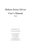
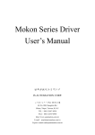
Mokon Series Driver
User’s Manual
V2.0
健昇科技股份有限公司
JS AUTOMATION CORP.
台北縣汐止市中興路 100 號 6 樓
6F,No.100,Chungshin Rd.
Shitsu, Taipei, Taiwan, R.O.C.
TEL:886-2-2647-6936
FAX:886-2-2647-6940
http://www.automation.com.tw
E-mail:[email protected]
Correction record
Version
Record
1.1
Add CN1-9 TLM+ Torque limit command
1.2
1 Adjust
2 Add
5. I/O Signal Definitions and CN1 Pin Assignments
20. Wiring of MPC3024 wiring board to Mokon driver
3 Modify description of CN1 Pin16 Hold
1.3
1. Chapter 5
I/O Signal Definitions and CN1 Pin Assignments
Pin5,6,7,13,14,15,16,30,31,34 descriptions—rewrite for more detail
Pin1,2 description—rewrite for more detail
1.4
1. Update Chapter 10,11,12 diagram
2. Update Chapter 20 Wiring of MPC3024 wiring board to Mokon driver
3. Update 15.1 Communication Protocol
2.0
YPV V2.0
1
Contents
1. Checking Mokon series products on delivery ................................................................................. 4
1.1 Servomotor nameplate descriptions....................................................................................... 4
1.2 Servomotor model.................................................................................................................. 5
1.3 Servo drive nameplate descriptions ....................................................................................... 5
1.4 Servo drive model.................................................................................................................. 6
1.5 Servo drive part names .......................................................................................................... 7
2. Servo drive installation precautions ................................................................................................ 8
2.1 Prevent foreign object intrusion............................................................................................. 8
3. Servo drive wiring precautions ..................................................................................................... 10
3.1 Main wiring.......................................................................................................................... 10
3.2 Wiring for the controller and the encoder............................................................................ 11
4. Servomotor installation precautions.............................................................................................. 12
4.1 Installation precautions ........................................................................................................ 12
4.2 Connect the servomotor with load precautions.................................................................... 12
4.3 Alignment ............................................................................................................................ 13
4.4 Handling oil and water......................................................................................................... 14
4.5 Cable stress .......................................................................................................................... 14
5. Encoder wiring and CN2 pin assignments of the servo drive ....................................................... 15
5.1 Signal waveform of feedback Encoder................................................................................ 15
6. Position command input circuit..................................................................................................... 17
6.1 From differential type line driver......................................................................................... 17
6.2 From open-collector output: ................................................................................................ 17
7. Analog command input circuit...................................................................................................... 18
7.1 Analog command input circuit ............................................................................................ 18
7.2 Digital input circuit interface............................................................................................... 18
8. Output interface circuits ................................................................................................................ 19
8.1 Digital output interface ........................................................................................................ 19
8.2 Encoder digital output interface circuit ............................................................................... 20
9. Position control interface .............................................................................................................. 21
10. Speed control interface.................................................................................................................. 22
11. Torque control interface ................................................................................................................ 23
12. Descriptions of Mokon servo drive input signals.......................................................................... 24
12.1 Input Signal definitions and CN1 pin assignments.............................................................. 24
12.2 Servo ON input (CN1-6)...................................................................................................... 27
12.3 RST Servo reset input (CN1-7) ........................................................................................... 27
12.4 TLM Torque limit input (CN1-13) ...................................................................................... 27
12.5 PRIH Forward rotation inhibited and NRIH reverse rotation inhibited inputs (CN1-14~15)28
12.6 Motor hold or PI/P control mode switch input (CN1-16).................................................... 28
12.7 MDO Operation mode ......................................................................................................... 29
2
13.
14.
15.
16.
17.
18.
19.
20.
21.
12.8 VCMD+ and TCMD+ inputs (CN1-1 and CN1-8).............................................................. 29
12.9 TLCMD+ Torque limit analog command input (CN1-9) .................................................... 30
12.10
+PPCMD –PPCMD, +NPCMD -NPCMD Position command inputs (CN1-26~29).. 30
12.11
SPD1 SPD2 SPD3 Internal speed switching inputs (CN1-32~35).............................. 31
Descriptions of Mokon servo drive Output signals....................................................................... 32
13.1 Output Signal definitions and CN1 pin assignments ........................................................... 32
13.2 ALM Servo alarm output (CN1-10) .................................................................................... 33
13.3 Brake motor brake release output (CN1-17)........................................................................ 33
13.4 Zero servo speed zero output (CN1-36) .............................................................................. 34
13.5 ITLM In torque limit output (CN1-37)................................................................................ 34
13.6 INS INP Speed/Position arrival output (CN1-18) ............................................................... 34
13.7 MON1 MON2 Analog monitor outputs (CN1-11~12) ........................................................ 35
13.8 Encoder output signals (CN1-19~24) .................................................................................. 35
User parameter settings and functions .......................................................................................... 36
14.1 Parameter settings and functions ......................................................................................... 36
Driver setup via PC communication ............................................................................................. 42
15.1 Setup communication protocol ............................................................................................ 42
15.2 Communication port to link with the servo driver............................................................... 43
15.3 Basic functions..................................................................................................................... 43
15.4 Common parameter.............................................................................................................. 44
15.5 Speed mode menu................................................................................................................ 50
15.6 Position mode menu............................................................................................................. 53
15.7 Torque mode ........................................................................................................................ 56
15.8 Motor Parameter Settings .................................................................................................... 58
15.9 Advanced Parameters .......................................................................................................... 59
15.10
Speed Loop Gain 1 ...................................................................................................... 59
15.11
Speed Loop Gain 2 ...................................................................................................... 60
15.12
Online Monitor ............................................................................................................ 62
Alarm display table ....................................................................................................................... 63
Connector pin assignments diagram ............................................................................................. 64
Servo drive dimension................................................................................................................... 65
Regenerate brake resistor selection guide ..................................................................................... 67
Wiring of MPC3024 wiring board to Mokon driver ..................................................................... 68
Appendix ....................................................................................................................................... 68
3
1. Checking Mokon series products on delivery
Follow the procedure below to check Mokon Series products upon delivery
Check the following items when Mokon Series products are delivered:
1.
2.
3.
4.
Check the packed products for damages that may have occurred during shipping.
Check whether the name and number of the delivered products are the same as those on the
delivery sheet.
Check whether the servomotor and servo drive capacity and encoder specification are the same
as the ordered.
In the case of special order, please carefully check the delivered products and contact our
company immediately if any item is incorrect.
The table below shows the standard set:
1. One servomotor
2. One servo drive
3. One 37PIN D type connector for CN1*
4. One 15PIN D type connector for CN2*
5. One connector for servomotor power line*
6. One encoder connector*
7. One copy of wiring description
* If cable is your option, they will be soldered ready with the cable.
1.1 Servomotor nameplate descriptions
Servo drive Model
Rated Output
Encoder Specification
Motor Rated Speed
Serial Number
4
1.2 Servomotor model
YBL13S75 - L
Z
Servomotor Serial Number
Design Revisions:
K Shaft length 20mm
S Shaft length 15mm
B With brake
Q Special shaft
U Terminal box type
V Oblique shaft
X Cable Connector type
Y Military standard connector
Z Power cable connector
M Water-proof L model
N Water-proof V model
Servomotor Pole Number
and Encoder Resolution
C 8P1024 P/R
D 8P2048 P/R
E 4P2500 P/R
F 4P5000 P/R
H 4P2048 P/R
I 8P5000 P/R
J 4P1024 P/R
L 8P2500 P/R
1.3 Servo drive nameplate descriptions
Servo drive Model
Serial Number
Version
Servo drive Specification
5
1.4 Servo drive model
YPV - 300-V
YPV Series Servo drive
Servodrive Capacity
040 0.4 KW
600
055 0.55 KW
750
075 0.75 KW
860
100 1 KW
1100
150 1.5 KW
1500
200 2 KW
2200
300 3 KW
3000
450 4.5 KW
6 KW
7.5 KW
8.6 KW
11 KW
15 KW
22 KW
30 KW
Type
V High resolution speed / Torque command: 12-bit resolution
6
1.5 Servo drive part names
The figure below shows the part names of the servo drive.
CN3 Communication Connector
Used to communicate with a personal
computer (RS-232) or a control panel
Charge Indicator
Lights when the main circuit
power supply is ON and stays
as long as the main circuit
power supply capacitor remains
charged. Therefore, do not
touch the Servo drive even after
the power supply is turned off if
the indicator is lit.
CN1 I/O Signal Connector
Used to input command
or sequence I/O signals.
Main Power Supply and Servomotor
Terminals
(RST) used for AC mains input(3 , 220Vac)
(E) Ground Terminal, must be connected
to prevent electrical shock
(UVW) Servomotor Cable Terminal
(B1 B2) Brake Resistance Terminal
(H1 H2) Servomotor Thermostat Terminal
CN2 Encoder Connector
Connects to the encoder
in the servomotor.
7
2. Servo drive installation precautions
The servo drive should be stored in the environment with ambient temperature range of 0-55 C (no
freezing) and relative humidity under 90% RH (no condensation).
Installation Orientation and Spacing:
1. When installing the servo drive, make the front panel containing connectors face outward and
take into consideration the easy connection/disconnection of CN1 and CN2 connectors for
measurement.
2. For multiple servo drive installation in the control cabinet, allow at least 40mm between each.
When installing servo drives side by side as shown in the figure below, allow at least 50mm
above and below each servo drive or install cooling fans to facilitate air circulation.
Servo drive Installation and Cooling Method
2.1 Prevent foreign object intrusion
1. Prevent the drilling and cutting chips from entering the servo drive during installation.
2. Avoid the odd objects like oil water and metal powder from entering the servo drive via
cooling fans.
3. If using fans for cooling, please install the filter properly at the ventilating hole, and
consider the surrounding environment to choose the best direction for ventilation.
4. Please install heat exchanger or air filtering system when installing in locations subject to
poisonous gas or excessive dust.
8
Extra Notices:
1. Do not install the servo drive in locations likely to be affected by oil and dust. If unavoidable,
please install the Servo drive in the airtight control cabinet and consider using ventilation filter.
Also use a protective cover over the Servomotor.
2. When installing multiple servo drives in one airtight control cabinet, allow at least 50mm
between, above and below each servo drive and leave 120mm for maintenance space. In addition,
to ensure the reliability and improve the product life, leave certain distance between the servo
drive and the cabinet ceiling so the temperature around the servo drive does not exceed 55 C
which might lead to poor ventilation.
3. A frequent use of the regenerative resistor may lead to a temperature higher than 100 C. Do not
put inflammables or heating deformable objects around. The wirings must also be kept away
from the resistor or severe damage will occur.
4. When installing near a source of vibration, install a vibration isolator to protect the Servo drive
from vibration.
9
3. Servo drive wiring precautions
Wiring precautions
3.1 Main wiring
1. Apply three-phase 220V AC mains through the NFB to the magnetic contactor, then
connect to the servo drive RST terminals. Consider installing a reactor and linear noise
filter if the local power supply quality is poor.
2. Connect the UVW terminals of the servo drive with the red, white and black cable lines of
the servomotor directly or via terminal board, on which the cable lines be secured with a
terminal plier and wrapped tightly to avoid incidental short-circuit, power interruption or
earth faults.
3. Make sure the cable lines are not damaged under stress. Be cautious of the cable wiring to
avoid as much as possible being subject to bending or tension.
4. If the servomotor is moving with the mechanism, arrange the bending section of the cable
line within the allowable curvature which is determined from the cable specification to
assure normal operation life.
5. Make sure the cable lines are not touched by sharp parts of the machine or pressed by any
heavy object.
6. Provide proper grounding wiring for the ground terminals of the servo drive and
servomotor.
7. H1 and H2 are the thermostat terminals for the servomotor. Strictly forbid to short circuit
them with the machine bed or falsely connect with U V W E terminals.
8. After fastening the main terminal board, the ends of the wiring terminals can be bended up
to be kept away from the front nameplate as shown be
10
3.2 Wiring for the controller and the encoder
1. Each pin of CN1 and CN2 must be soldered and checked carefully for correct pin number
Check the adjacent pins after soldering to avoid being incidentally shorted circuit by the
solder or unused leads.
2. Wrap the soldered leads with shrinkable tubes to keep from being touched by each other.
3. If the leads from CN2 must be extended, care must be taken in the connection section and
proper shielding measures must be adopted to suppress EMI noise.
4. Do not stretch tight the leads of CN2 to avoid wiring faults of the encoder.
5. Power cables and signal lines should not be arranged in close parallel, and the leads for
control signals should be twisted and shielded.
Note: Be cautious of the length of the wiring and the measures for noise shielding if Mokon series is
used in position control mode. If not using the line driver type, the PULSE GND must be connected
to DGND, or the lost pulse fault may occur.
CAUTION
1. Do not bundle power and signal lines together in the same duct. Leave at least 30cm (11.81 in.)
between power and signal lines.
2. Use twisted-pair wires or multi-core shielded-pair wires for signal and encoder (PG) feedback
lines.
3. The maximum length for signal input lines is 3m (118.11 in.) and for PG feedback lines is 20m
(787.40 in.).
4. Do not touch the power terminals for 5 minutes after turning power off because high voltage
may still remain in the servo drive.
5. Make sure the Charge Indicator is out before starting an inspection.
6. Avoid frequently turning power on and off. Do not turn power on or off more than once per
minute.
7. Since the servo drive has capacitors in the power supply, a high charging current flows for 0.2
seconds when power is turned on. Frequently turning power on and off will cause main power
devices like capacitors and fuses to deteriorate, resulting in unexpected problems.
11
4. Servomotor installation precautions
4.1 Installation precautions
Try to avoid water and oil exposure since the servomotor contains no water-proof structure. Install a
water-proof cover if it is used in a location that is subject to water or oil.
1. Servomotor cable line facing downward can prevent the oil and water from entering the
servomotor via cable line.
2. If the servomotor is installed vertically or with a slope, the cable line should be bended to
U-type to avoid the oil and water from entering via the cable line.
3. Carefully avoid the exposure of cable lines to oil and water that have adverse effects on
servomotor and encoder, also may cause malfunctions of the servo drive.
4.2 Connect the servomotor with load precautions
1. To mount a belt wheel, use the set screw to secure it on the shaft end if the motor shaft has a
keyway; Use a friction coupling if the motor shaft has no key way.
2. Use a special tool to dismantle the belt wheel, avoiding impact to the shaft.
3. Strictly forbid to exert force on the back cover of the encoder by hands or ropes when
moving the servomotor.
4. Strictly forbid the use of hammer to strike the shaft (likely to damage the encoder)
12
Avoid violent collision and vibration of servomotor when mounting
a belt wheel or a clutch! The encoder connecting with the shaft is
vulnerable under intense vibration which may adversely affect the
resolution and service life of the servomotor.
5. Do not change the encoder wiring direction.
6. Use a flexible connector. The round-off must meet with the allowable radial load.
7. Choose a proper pulley, chain wheel or timing belt that can meet with the requirement of
the allowable radial load.
8. If the servomotor is attached with a magnetic brake, either horizontal or vertical installation
is allowed. When the shaft is upward installed, the brake may normally make some noise.
4.3 Alignment
Align the shaft of the servomotor with the shaft of the apparatus, and then couple the shafts.
Install the servomotor so that alignment accuracy falls within the following range.
.
Measure this distance at four different positions around.
The difference between the maximum and minimum
measurements must be below 0.03mm (0.0012 in). (Turn
together with the coupling.)
.
Measure this distance at four different positions around.
The difference between the maximum and minimum
measurements must be below 0.03mm (0.0012 in). (Turn
together with the coupling.)
13
4.4 Handling oil and water
Install a protective cover over the servomotor if it is used in
a location subject to water or oil mist.
Also use a servomotor with an oil seal to seal the through shaft
section.
4.5 Cable stress
Make sure there are no bends or tension on the power lines.
Be especially careful to signal line wiring to avoid stress because the diameter of the core
wires is only 0.2 to 0.3mm (0.0079 to 0.012 in).
14
5. Encoder wiring and CN2 pin assignments of the servo drive
Motor RSO
Connector
Motor Side
Cable Color
Name of the
Signal
Servo drive
Side Pin No.
1
Green
A
1
2
White Grey
/A
2
3
Gray
B
3
4
White Gray
/B
4
5
Yellow
C
5
6
White Yellow
/C
6
7
Brown
U
7
8
White Brown
/U
8
9
Orange
W
9
10
White Orange
/W
10
11
Blue
V
11
12
White Blue
/V
12
13
Red
+5V
13
14
White Red
GND
15
Silver braided wire
Shielding
14
15
Case
5.1 Signal waveform of feedback Encoder
The figure below shows the forward rotation (CCW) waveform of the encoder
15
16
6. Position command input circuit
6.1 From differential type line driver
6.2 From open-collector output:
Example 1: Using an external power supply provided by the user
Note: Mokon Servo drive can be only connected with 24V external power supply.
Example 2: Using power supply built in the servo drive
17
7. Analog command input circuit
7.1
Analog command input circuit
7.2
Digital input circuit interface
18
8. Output interface circuits
8.1
Digital output interface
Example 1: Connecting to a relay output circuit
Example 2: Connecting to a photo coupler output circuit
19
8.2
Encoder digital output interface circuit
20
9. Position control interface
21
10. Speed control interface
22
11. Torque control interface
23
12. Descriptions of Mokon servo drive input signals
12.1 Input Signal definitions and CN1 pin assignments
Signal
Type
Pin
Name
Pin
No.
Common
+15V
3
Function Descriptions
+15V voltage
output
±15V volt with allowable 50mA output , spare for
external analog use.
-15V
4
-15V voltage
output
24G
5
Common
power ground for user control interface.
SON
6
Servo on
Digital signal for activating the servo drive when
connected with 24G.(internal 24V pull high)
RST
7
Alarm reset
Digital signal for releasing the servo drive when
connected with 24G.(internal 24V pull high)
TLM
13
Torque Limit
Digital signal for torque limit when connected
24G(internal 24V pull high)
PRIH
14
Forward Rotation Digital signal for inhibiting the forward rotation when
Inhibited
connected with 24G.(internal 24V pull high)
NRIH
15
Reverse Rotation Digital signal for inhibiting the reverse rotation when
Inhibited
connected with 24G.(internal 24V pull high)
HOLD
16
Motor HOLD
(forward and
reverse rotation
inhibited) Speed
Loop Control
OR
PI/P
+5V
30
DGND
31
MDO
34
Digital signal for inhibiting the forward and reverse
rotations when connected with 24G, in position mode,
the input pulse counter will be cleared; or switching
between PI / P control modes under the speed operation
mode . (The function of this pin is selected in the
"common Parameter" menu .)(internal 24V pull high)
5V voltage output 5 volt with allowable 50mA output, spare for external
use.
5V ground output 5V power ground, also ground for ±15V.
Operation Mode connected with 24G will switch the operation mode.
switch
(defined by Common parameter->Control mode
selection)
S / P Speed mode < - > Position mode P / T Position
mode < - > Torque mode
S / T Speed mode < - > Torque mode
(internal 24V pull high)
24
Signal Type Pin Name Pin No.
SPEED
VCMD+
1,
8
Function Descriptions
Speed command
During driver set at speed mode:
Enable the motor to run at speed
proportional to the speed command voltage .
At ±10V input , the motor runs ±3000rpm ,
or ±2000rpm . Positive voltage corresponds
to forward rotation , while negative voltage
corresponds to reverse rotation .
(pin8 can also act as low resolution speed
command input)
TORQUE
AGND
2
Analog ground
Analog signal ground
TCMD+
1
Torque command During driver set at torque mode:
Enables the motor to output torque
proportional to the torque command
voltage . At ±10V , the motor output 300%
rated torque .
TLM+
9
Torque limit
command
Enabled while TLM (pin13) active low,
At ±10V , the motor output is limited at
300% rated torque .
The function is also available in speed
mode.
AGND
2
Analog ground
Analog signal ground
25
Signal Type Pin Name Pin No.
Position
EPI
25
Function Descriptions
External Power
input
+24V External Power input for open collector
pulse driver.
Command
(If TTL or line driver pulse source, the EPI
power input is no need)
Ref 7. Position Command Input Circuit
+PPCMD
26
Forward rotation Forward rotation pulse Input+
pulse Input+
(CW+ / Pulse+ /A+)
-PPCMD
27
Forward rotation Forward rotation pulse Inputpulse Input(CW- /Pulse- /A-)
+NPCMD
28
Reverse rotation Reverse rotation pulse Input+
pulse Input+
(CCW+ / Dir+ /B+)
-NPCMD
29
Reverse rotation Reverse rotation pulse Inputpulse Input(CCW- / Dir- /B-)
Common EG1/SPD
Signal for
Position and
Speed
EG2/SPD2
Command
32
Electronic gear 1 Input signal as electronic gear selection 1 in
Speed selection 1 position operation mode or as speed selection 1
in speed operation mode .
33
Electronic gear 2 Input signal as electronic gear selection 2 in
Speed selection 2 position operation mode or as speed selection 2
in speed operation mode .
EG3/SPD3
35
Electronic gear 3 Input signal as electronic gear selection 3 in
Speed selection 3 position operation mode or as speed selection 3
in speed operation mode .
26
12.2 Servo ON input (CN1-6)
This signal is used to turn on and off the power to the servomotor.
Note:
1. Contact this input to ground will make the Mokon driver ready to receive the command pulse or
analog voltage input.
2. Open the contact will make the servo motor free run. Do not use this signal to work as motor
stop signal.
12.3 RST Servo reset input (CN1-7)
This signal is used to reset the servo drive after clearing the servo alarm.
12.4 TLM Torque limit input (CN1-13)
This signal, together with the TLCMD+ analog voltage input (CN1-9) torque limit signal, is to
protect the apparatus or work piece. If the input torque limit exceeds the maximum motor rated torque,
then the maximum motor rated torque is the maximum torque limit.
A too low torque limit might cause the problem of insufficient torque during acceleration/
deceleration.
27
12.5 PRIH Forward rotation inhibited and NRIH reverse rotation inhibited inputs (CN1-14~15)
These two signals force the moving part of the apparatus to stop if they travel over the allowable
range of motion. Connect the overtravel limit-switch signals to the correct pins (PRIH for forward
overtravel, NRIH for reverse overtravel) of the servo drive CN1 connector. (as shown below)
12.6 Motor hold or PI/P control mode switch input (CN1-16)
If Motor Hold function is selected, the servomotor will be stopped and held still when CN1-16 is
connected with 24G. The servomotor is decelerated according to the programmed profile.
If PI/P Control Mode Switch function is selected, the speed loop will be changed from PI mode to P
mode when CN1-16 is connected with 24G and. The mode switching function is described below:
Applications:
1. To suppress the overshoot during acceleration/deceleration under the speed operation mode.
2. To suppress the undershoot or decrease the settling time under the position operation mode.
28
12.7 MDO Operation mode
If the CNTL parameter is set in the “Common Parameter" menu as S/P (speed/Position), P/T
(Position/Torque), or S/T (Speed/Torque) mode, this input signal enables the switching between
operation modes.
For example: If CNTL is set as S/P mode, when CN-34 and 24G is not connected, the servo drive is
in Speed operation mode, when connected; the servo drive is switched to Position operation mode.
12.8 VCMD+ and TCMD+ inputs (CN1-1 and CN1-8)
VCMD+: When the servo drive is in S Mode or is switched to S mode, this signal is used as analog
speed command input. The input voltage scale can be modified at the VMDL parameter contained in the
“Speed Parameter" menu. The value of the VMDL parameter defines the input voltage which
corresponds to the rated speed, with positive voltage for forward rotation, and negative voltage for
reverse rotation.
TCMD+: When the servo drive is in T Mode or is switched to Torque operation mode, this signal is
used as analog torque command input. If the input voltage is 10V, the motor outputs 300% of the rated
torque.
Note: CN1-1 is for high-resolution analog signal input (12 BIT). Please purchase YPV-XXX-V
series servo drive if high-resolution analog input is needed. The input pin of the standard analog input
(resolution 10 BIT) is CN1-8.
29
12.9 TLCMD+ Torque limit analog command input (CN1-9)
This signal is used as analog torque limit command input when CN1-13 is connected with 24G. If
the input voltage is 10V, the limit range corresponds to 300% of the rated torque of the motor.
12.10 +PPCMD –PPCMD, +NPCMD -NPCMD Position command inputs (CN1-26~29)
When the servo drive is in P Mode or switched to Position operation mode, these signals are used as
position command inputs. The type of the command can be changed within the parameter.
The position command signals can be any of the following
forms (refer to 6. Position command input circuit):
1. Differential type
2. +24V open-collector type
3. +5V open-collector type
30
12.11
SPD1 SPD2 SPD3 Internal speed switching inputs (CN1-32~35)
ELGN1 ELGN2 ELGN3 Electronic Gear Numerator Switching Inputs (CN1-32~35)
When the servo drive is in S Mode or switched to Speed operation mode, and if the internal speed is
enabled, the internal speed command can be selected by properly connecting one among CN1-32
(SPD1), CN1-33(SPD2) and CN1-35(SPD3) to 24G. The three pins correspond to three different internal
speed commands which are defined by the parameters Internal Speed 1, Internal Speed 2 and Internal
Speed 3 (Unit: RPM) in the “Speed Parameter"menu.
When the servo drive is in P Mode or switched to Position operation mode, the numerator of the
electronic gear ratio can be selected by properly connecting one among CN1-32 (ELGN1), CN1-33
(ELGN2) and CN1-35 (ELGN3) to 24G. The three pins correspond to three different numerators that are
defined by the parameters Numerator 1, Numerator 2 and Numerator 3 in the “Position Parameter"
menu, where a common denominator of the electronic gear ratio is also programmed
.
31
13. Descriptions of Mokon servo drive Output signals
13.1 Output Signal definitions and CN1 pin assignments
Signal Type
Common
Pin Name Pin No.
Function Descriptions
ALM
10
Servo Alarm
Digital signal for alarm
BRAKE
17
Motor Brake
Release Signal
Digital signal for releasing the motor
brake
Speed
ZERO
36
Motor Low Speed
Output
Digital signal output indicating the
servomotor is running at speed lower
than the user setting .
In Torque
Limit
ITLM
37
Output In Torque
Limit
is saturated at the torque limit value in
torque is saturated at the torque limit
value in torque operation mode .
Speed/Position
Common
Signal
INP/INS
18
Position/Speed
Arrival
Digital signal output for indicating the
value of position error counter is smaller
than the user setting in position operation
mode , or the motor speed is smaller than
the user setting in speed operation mode .
Analog Output
MO1
11
Analog output 1
Analog output
MO2
12
Analog output 2
Analog output
A
19
Encoder A phase
/A
20
Differential , line driver digital output
signal A phase .
B
21
Encoder B phase
/B
22
Differential , line driver digital output
signal B phase .
Z
23
Encoder Z phase
/Z
24
Differential , line driver digital output
signal Z phase .
Encoder Signal
Output
32
13.2 ALM Servo alarm output (CN1-10)
This signal indicates that an abnormal state of the servo drive occurs.
13.3 Brake motor brake release output (CN1-17)
If CN-17 is programmed as the brake release signal, when the driver is enabled through the contact
of SON (CN 1-6) and 24G, the brake release signal will be issued after a delay time defined by the MBR
parameter in the “Common Parameter"menu.
If CN-17 is programmed as the servo ready signal (default), after the driver is enabled and no alarm
has been detected, the servo ready signal will be issued immediately.
When the system power is turned off, the servomotor with
brake prevents the movable parts from dropping due to gravity.
The brake built in the servomotor is of passive type and is intended only for holding the motor and
cannot be used to actually stop a rotating motor. Be sure that the holding brake is applied after the motor
is stopped. The braking torque is at least 120% of the rated motor torque.
33
13.4 Zero servo speed zero output (CN1-36)
This signal is used to indicate that the speed of the servomotor is lower than or equal to the ZSPD
parameter set in the “Speed Parameter" menu and issued by connecting CN1-36 to 24G.
13.5 ITLM In torque limit output (CN1-37)
When the servo drive CN1-13 (TLM) is connected with 24G or if the output torque is saturated at
the limit set by the driver, CN1-37 will be connected with 24G to issue the In Torque Limit signal.
13.6 INS INP Speed/Position arrival output (CN1-18)
If the servo drive is set as S Mode, when the motor speed is equal to or higher than the INS
parameter set in the “Speed Parameter" menu, CN1-18 will be connected with 24G to issue the
Speed Arrival signal.
If the Servo drive is set as P Mode, when the value of the position error counter is equal to or lower
than the INP parameter set in the “Position Parameter"menu, CN1-18 will be connected with 24G to
issue the Position Arrival signal.
34
13.7 MON1 MON2 Analog monitor outputs (CN1-11~12)
These output signals are for monitoring the dynamic states of the servo drive and can be selected in
the “Common Parameter" menu, in which the scale, offset and resolution of the output signals are
also defined
MON1: as Monitor Channel A defined the “Common Parameter" menu;
MON2: as Monitor Channel B defined the “Common Parameter" menu
13.8 Encoder output signals (CN1-19~24)
Encoder output signals, derived from the servo drive, can output to an external Host Controller. The
Host Controller then uses these signals in its control circuit.
35
14. User parameter settings and functions
14.1 Parameter settings and functions
YPV driver parameter definitions
parameter
no.
register
0
EEPW
0:write parameters into
EEPROM
1
CNTL
Servo control mode
0 = Torque mode
1 = Speed mode
2 = Position mode
3 = Speed/Position mode
4 = Position/Torque mode
5 = Speed/ Torque mode
2
PMOD
function/data
mode
initial
unit
range
0
0
S、P、
3
0~5
P
0
0~2
T
PULSE CMD TYPE
0=PULSE/DIR
1=A/B
2=CW/CCW
Note: no valid for YPV ver 2
3
Ta
acceleration time for speed
mode linear acceleration
profile.
Note: internal generated
profile, if use external profile
generator set this parameter to
0
S
0
ms
0~
10000
4
Td
deceleration time for speed
mode linear acceleration
profile.
Note: internal generated
profile, if use external profile
generator set this parameter to
0
S
0
ms
0~
10000
5
Tsa
acceleration time for speed
mode S acceleration profile.
Note: internal generated
S
0
ms
0~
10000
36
remark
profile, if use external profile
generator set this parameter to
0
6
Tds
deceleration time for speed
mode S acceleration profile.
Note: internal generated
profile, if use external profile
generator set this parameter to
0
S
0
ms
0~
10000
7
PACC
Pulse mode control
acceleration time.
Note: internal generated
profile, if use external profile
generator set this parameter to
0
P
0
ms
0~
10000
8
SP0
0: internal speed generator
disable
1: internal speed generator
enable
S
0
9
SPD1
speed1 of internal speed
generator
Note: selected by SPD1
digital input, while SP0=1
S
500
RPM
- rated
RPM
~ +
rated
RPM
10
SPD2
speed2 of internal speed
generator
Note: selected by SPD2
digital input, while SP0=1
S
1000
RPM
- rated
RPM
~ +
rated
RPM
11
SPD3
speed3 of internal speed
generator
Note: selected by SPD3
digital input, while SP0=1
S
2000
RPM
- rated
RPM
~ +
rated
RPM
12
VMDL
speed command voltage to
motor rated speed
S
10
V
0~10
S、T
0
0~1
Note: 10 means 10V for 2000
RPM rated speed motor.
13
SPDO
Voltage input offset for
37
± 1024
speed/torque mode
14
ZSPD
zero speed range
Note: when motor speed
equivalent voltage less than
the setting voltage the
CN1-37 (ZERO) will make.
S
50
RPM
0~
rated
RPM
15
INS
speed agreed range.
Note: when motor speed
equivalent voltage less than
the setting voltage the
CN1-18 (INS) will make.
S
2000
RPM
0~
rated
RPM
16
TQL
torque limit in speed /position
mode
Note: function only valid
while CN1-13(TLM) short to
24G
S、P
300
%
0 ~300
17
TLCS
torque limit source
0: internal
1: external analog command
voltage (from CN1-9)
S、P
1
18
TQCA
filter time constant for torque
command input
Note: Larger time constant
will decrease the band width
of response
T
15
19
DOLO
output polarity
0: normal open
1: normal close
S、P、
0
0~1
R/W
2000
0~
R/W
20
TSL
0~1
us
R/W
15 ~
10000
T
speed limit for torque mode
T
rated
RPM
21
KVP1
proportional gain1 for speed
loop
S
3000
0~
30000
22
KVP2
proportional gain2 for speed
loop
S
3000
0~
30000
23
KVI1
integral gain1 for speed loop
S
130
0~
30000
24
KVI2
integral gain2 for speed loop
130
0~
30000
25
SPDB
dead band of speed command
0
0~
38
rated
RPM
26
KPP1
27
proportional gain for position
loop
S
300
0~
30000
Not available
28
SSPD
speed loop gain switch level
(speed lower than SSPD,
switch from gain1 to gain2)
300
29
CNTR
Refer appendix 1
30
DO17
function configuration of
CN1-17 0: active while servo
ready
1: brake release while P037
(MBR) time out
S、P、
In-position range
Note: position error falls into
this range the CN1-18 (INP)
will be active
P
100
%
0~
300
0~1
T
31
INP
Pulse
32
ELGN
numerator of gear ratio
P
10
1~
30000
33
ELGN1
numerator 1of gear ratio
(selected by EG1 digital
input)
P
10
1~
30000
34
ELGN2
numerator 2 of gear ratio
(selected by EG2 digital
input)
P
100
1~
30000
35
ELGN3
numerator 3 of gear ratio
(selected by EG3 digital
input)
P
1000
1~
30000
36
ELGD
denominator of gear ratio
P
10
1~
30000
37
MBR
brake release delay timer,
after power on the CN1-17
BRAKE will active during
MBR time out
S、T、
500
ms
0~200
0
P
38
MONO1
offset of monitor output1
0
mv
-127~1
27
39
MONO2
offset of monitor output2
0
mv
-127~1
27
39
R/W
40
MONT1
source of monitor output1
0:servo motor current
1:speed
2:position error counter
1
0~2
41
MONT2
source of monitor output2
0:servo motor current
1:speed
2:position error counter
1
0~2
42
MONL
speed monitor output voltage
of rated speed
±10V =±2000 OR ±3000
RPM
±8V = ±2000 OR ±3000
RPM
10
V
0 ~ 10
43
MTYP
Motor pole number
8
pole
2 ~ 48
44
RPM
Motor rated RPM
2000
RPM
0~
10000
45
ENCO
Encoder pulses per motor
revolution
2500
Pulse
1~
10000
46
IPEK
Driver peak current
47
DCDY
Regenerate discharge duty
cycle
48
POEN
Numerator of encoder output
ratio
1~
32767
49
POED
Denominator of encoder
output ratio
1~
32767
50
IMON
Real time current value for
monitoring
ma
RO
51
SMON
Real time speed value for
monitoring
RPM
RO
52
OSLV
over-speed limit
S
3000
RPM
0~
10000
53
PERZ
over error counter limit
Note: 0: disable PERZ
function
P
3000
0
pulse
1~
32766
S
1
54
not available
55
not available
56
ADO
ma
voltage command source
1 = high resolution (always
choose)
40
50
%
0~
100
0~1
Note: YPV ver2 is 14 bit
resolution
57
not available
58
not available
59
60
MRO
DI-16
61
62
65
T、S、
CN1-16 DI function selection
0 = CN1-16 works as HOLD
function
1 = CN1-16 works as PI and
P compensation switch
1
0~1
S、P
0
0~1
T
0
0~1
R/W
S、P、
0
0~1
R/W
P
not available
TSLO
63
64
motor rotation direction
0: positive command voltage
in CCW direction
1: positive command voltage
in CW direction
speed limit source of torque
mode
0: internal
1: external(analog voltage in)
not available
DILS
SVER
polarity of over-travel limit
input CN1-14 and CN1-15
0: normal, ground input to
PRIH , NRIH input will
activate the function.
1: invert, open input to
PRIH , NRIH input will
activate the function.
Software version
T
RO
41
15. Driver setup via PC communication
15.1 Setup communication protocol
1. Right click the mouse on my computer icon,
Choose the “Properties” item
2. Select “Hardware” -> “Device manager”
3. Select “Ports (COM & LPT) and choose the com 4. Select “Port Settings” to change parameters
port you are connecting to.
Bits per second = 9600
Data bits = 8
Parity = None
Stop bits = 1
Flow control = none
42
15.2 Communication port to link with the servo driver
Start -> Program Files-> JS Automation->YPV
The figure left shows the display of ComPort Setting,
please choose the Communication Port used by your
computer first.
15.3 Basic functions
Mokon Servo drive has the following five menus for parameter setting:
1. Common Parameter
2. Speed Mode Parameter
3. Position Mode Parameter
4 Torque Mode Parameter
5. Motor Parameter
43
15.4 Common parameter
Select control mode
Mokon servo drive has six operation modes for selection
T Mode:
Torque mode, which is a single mode and cannot be switched through CN1-34 (MDO)
S Mode:
Speed mode, which is a single mode and cannot be switched through CN1-34 (MDO)
P Mode:
Position mode, which is a single mode and cannot be switched through CN1-34 (MDO)
S/P Mode:
Speed <-> Position mode, which can be switched through CN1-34 (MDO)
P/T Mode:
Position <-> Torque mode, which can be switched through CN1-34 (MDO)
S/T Mode:
Speed <-> Torque mode, which can be switched through CN1-34 (MDO)
44
Electromagnetic brake release time (MBR)
MBR is effective only when CN1-17 is programmed as the Motor Brake Release function.
Available range: 0~ 1000 ms
Monitor voltage (MOVL)
45
This field is used to set the maximum output voltage of the monitoring signals for both channel
A and channel B, default value is 10V.
If S Monitoring is selected, the maximum output voltage corresponds to the motor rated speed.
If I Monitoring is selected, the maximum output voltage corresponds to the motor 300% rated
current.
If P Monitoring is selected, the maximum output voltage corresponds to the tracking error
setting set in the “Motor Parameter" menu.
Motor definition rotation
You can choose positive command voltage to CW rotation or CCW rotation.
Select CN1-16 function
46
You can choose CN1-16 as
1. Hold function input, when the input active will hold the servo immediately and clear the error
counter in position mode.
2. PI/P Speed Loop Control Mode Switch input, when the input active, the driver will enter a P
speed control mode.
Select CN1-17 function
You can choose CN1-17 as
Servo Ready output: CN1-17 will be closed immediately when the servo drive is turned on and turn
off when an alarm has been detected to signal the controller.
Electromagnetic brake control output: When SON (CN1-6) is engaged, CN1-17 will not be closed
until after a delay time set by the Electromagnetic brake release time parameter; when SON (CN1-6) is
disengaged, CN1-17 will not be open until after a delay time set by the Electromagnetic brake release
time parameter.
47
Output logic selection
Define the logic of CN1-10, CN1-17, CN1-18, CN1-36, CN1-37 output signals
1. Positive logic 0, the secondary side of the photocoupler is closed when the output signal is
issued.
2. Negative logic 1, the secondary side of the photocoupler is open when the output signal is issued.
Logic for positive and negative limit
Logic for positive and negative limit:
Define the input logic of CN1-14 (Forward/Positive Rotation Inhibited PRIH) and CN1-15
(Reverse/Negative Rotation Inhibited NRIH).
1. Positive logic, motor forward and reverse rotations are inhibited when CN1-14, CN1-15 are connected
with 24G (CN1-5) respectively.
2. Negative logic, motor forward and reverse rotations are inhibited when CN1-14, CN1-15 are not
connected with 24G (CN1-5) respectively.
48
Upload
The input parameters will be transmitted and stored in the registers of the servo drive. (The
parameters will not be maintained in the servo drive after the power is turned off.)
input
Upload and Program
After entering the parameters, it is necessary to press this button to write these parameters stored in
the registers onto the FLASH ROM in the servo drive. These parameters will thus be maintained in the
servo drive and not disappear after the power is turned off.
49
15.5 Speed mode menu
Voltage Command
Input voltage (VMDL)
Allowable range: ±2V ~ ±10V
Used to scale the input voltage command (CN1-1 or CN1-8). Set the maximum input voltage of the
speed command, and this maximum voltage corresponds to the rated speed of the servomotor.
Offset voltage(SPDO)
Allowable range: -1024 ~ +1024 mV
Used to compensate for the offset of the voltage command. Set the offset voltage according to the
actual condition, and the desired speed command is obtained internally by subtracting this setting from
the input voltage (CN1-1 or CN1-8).
Speed Command Channel (ADO)
Select the speed analog command channel
AD, analog command input from CN1-8, resolution 10 Bit
VCO, analog command input from CN1-1, resolution 12 Bit (Mokon driver is suggest to use VCO)
50
Lowest speed (SPDB)
The servo drive will work only when the speed command is higher than the minimum motor speed
setting. If controlled by the numerical controller, set this value to 0.
Minimum speed command can be set under the following
situations:
* The servomotor cannot be stopped at zero analog
command.
* The analog speed command is jammed by large noise
and thus the servomotor cannot be stopped.
Internal Speed Settings
Internal Speed (SP0)
Enable or disable the function of CN1-32 (the first internal speed), CN1-33 (the second
internal speed) and CN1-35 (the third internal speed) in the speed operation mode.
1st Internal Speed Settings
2nd Internal Speed Settings
3rd Internal Speed Settings
To set the pre-defined internal speed command.
If the Internal Speed Enable Setting (SP0) is set as “Enable", the 1st internal speed (SPD1) will
be executed if CN1-32 is connected with 24G.
If the Internal Speed Enable Setting (SPO) is set as “Enable", the 2st internal speed (SPD2) will
be executed if CN1-33 is connected with 24G.
If the Internal Speed Enable Setting (SPO) is set as “Enable", the 3st internal speed (SPD3) will
be executed if CN1-35 is connected with 24G.
Acceleration/Deceleration Time
51
Linear acceleration time(Ta)
Linear deceleration time(Td)
Setting the linear deceleration/ deceleration time constant
S curve acceleration time(Tsa)
S curve deceleration time(Tsd)
Setting the S curve deceleration/ deceleration time constant
If controlled by a host numerical controller, set all the acceleration/deceleration time to 0.
Before setting S-type acceleration/deceleration time, linear acceleration/deceleration time must be set;
otherwise the characteristics of S-type acceleration/deceleration cannot be performed.
Output Settings
Zero Speed
Under speed operation mode, when the motor speed is lower than or equal to the set value of ZSPD,
CN1-36 will be conducted.
In Speed
Under speed operation mode, when the motor speed is higher than or equal to the set value of INS,
CN1-18 will be conducted.
52
15.6 Position mode menu
Position Command
Command Type
Mokon servo drive can accept the following three types of command
Filter frequency
Filter frequency is only valid if the
“Command type” is selected as “A+B WITH FILTER”
Pulse command trigger type
To select the polarity of the command pulse, Hi to Low trigger or Low to Hi trigger.
53
In position range
To set the range when the error count pulse is less than the value driver will take it as complete of
positioning the CN1-18 will be engaged.
Electronic Gear
Denominator
The common denominator of the 4 numerator.
Numerator
Available range: 0 ~ 32767
If the servo motor feedback encoder is 2500ppr (2500 x 4 pulse per revolution) and the
Denominator is set to 5000, the Numerator set to 10000. The controller command pulse will be 5000
pulses to run the motor one revolution.
Command pulses to
=
run one revolution
2500 (Encoder pulse per
revolution) X 4
/
10000 (Numerator)
5000 (Denominator)
Numerator1
Under the position operation Mode, Numerator 1 will be selected as the numerator of the electronic
gear ratio when CN1-32 is connected with 24G.
Numerator2
Under the position operation Mode, Numerator 2 will be selected as the numerator of the electronic
gear ratio when CN1-33 is connected with 24G.
Numerator3
Under the position operation Mode, Numerator 3 will be selected as the numerator of the electronic
gear ratio when CN1-35 is connected with 24G.
Note:
1. When A+B pulse mode is selected as pulse command input, the pulse count of electronic gear
must multiply by 4.
2. When electronic gear ratio is set too large, the servo motor may caused jiggles, the adequate
acceleration and deceleration is required.
54
Encoder Output Divider Ratio
Numerator of divider
Denominator of divider
The encoder output is divided from the original encoder signal and the output pulse rate will be
Output pulse = Original pulse * (Numerator / Denominator)
Say your servo system encoder is quadrature pulse 2500ppr, the equivalent pulse is 10,000 pulses per
revolution, if you want to get the out put at 2000 ppr (equivalent pulse), you must set the Denominator to
10,000 and Numerator to 2000.
Divider output phase
The output qdudratue pulse can be the same phase with the incoming encoder signal or inverse with
the incoming. Choose” Standard” means the same phase, inverse means inverse phase.
Encoder input filter frequency
The digital filter of the input encoder signal, there are 4 choices
10MHz,5MHz,2.5MHz and 1.25MHz
Acceleration/deceleration time
The position mode internal acceleration/deceleration time.
If a controller with adequate acc/dec profile control function, the time constant must set to 0.
Under position operation mode this function can
provide acceleration/deceleration function for the
following situations:
1. The host controller cannot perform the
acceleration/deceleration function;
2. The electronic ratio is too high (>10 times) This
function does not affect the positioning
precision.
55
15.7 Torque mode
Torque mode Settings
Torque command input filter time
Range available: 0~100us
Torque command is filtered, if the time constant is small, response will be fast but noise may come
into system, large filter time constant will filter out high speed command or noise.
Percent of torque limitation
Range available: 0~ 300 %
Internal torque limit.
Torque speed limitation
Speed limit of torque mode when internal torque limit is selected.
56
Torque speed limit option
There are 2 type of torque speed limit
1. Internal torque speed limit, choose this option, the Torque speed limitation will be effective.
2. External analog torque speed limit, choose this option, the CN1-8 speed input will be the speed
limit of torque command (CN1-1)
Torque limit command option
There are 2 type of torque limit
3. Internal torque limit, choose this option, the Torque speed limitation will be effective.
4. External analog torque limit, choose this option, the CN1-9 torque limit input will be the limit of
torque command (CN1-1)
57
15.8 Motor Parameter Settings
Motor Parameter Settings
Pole : the servo motor poles according to the motor specifications
Rated speed: the servo motor rated speed according to the motor specifications
Encoder type: the feedback encoder pulse per revolution according to the motor specifications
Max current: the 3 * rated current of servo motor, less is possible but will limit the motor
instantaneous torque.
Driver Protection Setting
Discharge Duty Cycle: use 50% as regular condition.
Over Speed protection: To set the effective operation speed range of the servo motor.
Position error range: To setup the accumulative inaccuracy of the driver, if the value is excessive,
error code 9 will occur.
Note: For high friction system, the error code 9 may occur owing to KPP value is too small.
58
15.9 Advanced Parameters
There are 4 sub functions of Advanced Parameters
1. Speed Loop Gain 1
2. Speed Loop Gain 2
3. Monitor
4. Unit Conversion
15.10
Speed Loop Gain 1
The KVI,KVP of speed loop gain1 is used as the speed is higher than SSPD setting value.
KVI : Speed loop integral constant
KVP : Speed loop proportional gain
KPP : Position loop proportional gain
59
15.11
Speed Loop Gain 2
The KVI,KVP of speed loop gain2 is used as the speed is lower than SSPD setting value.
KVI : Speed loop integral constant
KVP : Speed loop proportional gain
SSPD : speed loop gain1 and speed loop gain2 switching level at speed of % rated speed
Note:
KVI: corresponds to the static stiffness of the speed loop, and is the inverse of the integral time
constant of the speed compensator. A higher set value means a shorter integral time, and consequently a
shorter response time is expected. This parameter is interrelated with KPP and should be tuned to induce
no mechanical vibration.
Default value (130) Maximum value (32767)
KVP: corresponds to the dynamic response of the speed loop, and is the proportional gain of the
speed compensator. This parameter should be tuned properly according to the load inertia, and the larger
the KVI parameter is tuned, the shorter the rise time of speed response will be.
Default value (3000) Maximum value (32767)
KPP: corresponds to the dynamic response of the position loop, and is the proportional gain of the
position compensator under the position operation mode. This parameter should be tuned properly
dependent on the bandwidth of the internal speed loop, and the larger the KPP parameter is tuned, the
shorter the rise time of position response will be.
Default value (300) Maximum value (32767)
The normal sequence for tuning servo gains is: KVP KVI KPP
The following figures show the measured waveform of Monitor voltage signal for different tuning
results in the oscilloscope.
60
Tuning procedure for the speed loop.
1. Set all the Acceleration/Deceleration Time settings (Ta, Td, Tsa, Tsd) to zeros in the “Speed
Parameter" menu.
2. Set the Torque Filter Time Constant (TQCA) to zero in the “Torque Parameter" menu.
3. Set the initial value of KVI as zero and use the default value (3000) for KVP in the “Speed
Parameter" menu.
4. Measure the I Monitor (torque monitoring signal, which can be selected in the “Common
Parameter" menu) with CH1 in the oscilloscope and adjust the magnitude of the speed command. The
speed command for the tuning procedure is of a step waveform and can be effectively generated by use
of the Motor Hold function (CN1-16).
During the whole tuning procedure, keep watching the I Monitor signal and adjust the magnitude of the
speed command accordingly so that the waveform of the I-Monitor signal is not saturated.
5. Measure the S Monitor (speed monitoring signal, which can be selected in the “Common
Parameter" menu) with CH2 in the oscilloscope and the speed command (CN 1-1 or CN1-8) with CH3
in the oscilloscope. Slowly adjust the KVP parameter in the “Speed Parameter" menu. The
adjustment should not stop until the rising slope of the S Monitor signal is close enough to the speed
command and no oscillation appears along the S Monitor trace.
The steady state error normally appears because the KVI parameter is zero during this step.
6. Slowly adjust the KVI parameter in the “Speed Parameter" menu with the default value (130) as a
first trial guess. The adjustment should not stop until the settling time of the S Monitor signal is as short
as possible while the overshoot of the S Monitor signal is less than 5 % (or 10%) and appears only once.
No sustained oscillation is allowed after this adjustment.
Note1. If the servomotor is installed in a ball screw driven machine bed, take caution of the travel limits
so that no collision may occur.
2. A well-tuned speed loop can guarantee the precision of machining and cut the job time as well. Make
sure not to operate a servo drive that causes the machine bed oscillatory due to de-tuned gains.
The overshoot is large due to high KPP or KVP. Try to reduce
KVP
or KPP.
The system is oscillatory due to high KVI. Try to reduce KVI.
The system is tuned properly.
61
15.12
Online Monitor
Use Read button to read the under monitoring data and stop to exit.
62
16. Alarm display table
Status Display
Description
Solution
0
READY
Servo system is ready. The main power
cable and the encoder cable from the
servomotor are connected correctly.
The servomotor can start a normal
operation
1
OC
An abnormally big instantaneous current Check whether the load exceeds the
triggers the OC alarm. The Machine will rated value, any main circuit
stop.
component is damaged, or output is
short-circuited.
2
OV
An abnormally high DC Bus voltage due
to too heavy load inertia or frequent
dynamic braking triggers the OV alarm.
The machine will stop.
3
OL
4
OH
An over 150% rated load lasting for one Check the reason of overload.
minute triggers the OL alarm. The
machine will stop.
The temperature over 135°in the
Check the ambient temperature and
servomotor winding or over 85°in the
the ventilation condition.
Check whether the load inertia is over
the specification and take into
consideration an extra regenerative
braking resistor.
heat sink of the servo drive triggers the
OH alarm. The machine will stop.
5
OS
An over 120% of the rated servomotor
Check whether the speed command
speed triggers the OS alarm The Machine exceeds the allowable value or the
will stop.
load is over the specification.
6
EE
A broken encoder wiring or an incorrect
wiring of the UVW feedback signals
triggers the EE alarm. The machine will
stop.
Refer to the wiring diagram and
check the wiring again.
7
LPF
Internal power supply of logic block
failure.
Send back to repair.
8
RESET
The servo drive control system is reset.
The system will start again after the
alarm is cleared.
9
OVF
An overflow of the position tracking error Check whether the load is over the
triggers the OVF alarm. . The machine
specification or the frequency of
will stop.
position pulse command is too high.
63
17. Connector pin assignments diagram
RS1
1
2
3
4
5
6
U
V
W
E
H1
H2
MS3102A24-11P
A
B
C
D
E
F
G
H
I
-
+
H1
U
V
W
E
E
H2
R20 and D-15P Pin Table
Rs0
1
2
3
4
5
6
7
8
9
10
11
12
13
14
15
16
green White grey White yellow White red black brown White orange White blue White shielding
Cn2
green
grey
yellow
brown
orange
blue
NC
D-15P
A
/A
B
/B
C
/C
1
2
3
4
5
6
+5V 0V
13
14
U
/U
W
/W
V
/V
7
8
9
10
11
12
case
15
2E20-29P and D-15P Pin Table
Rs0
A
B
C
D
E
F
G
H
J
K
L
M
N
P
R
S
T
green White grey White yellow White red black brown White orange White blue White shielding
Cn2
green
grey
yellow
brown
orange
blue
NC NC
D-15P
A
/A
B
/B
C
/C
1
2
3
4
5
6
+5V 0V
13
14
15
64
U
/U
W
/W
V
/V
7
8
9
10
11
12
case
18. Servo drive dimension
Dimension (mm)
Model
A
B
D
E
W
H
Weight
(kg)
YPV-040
YPV-055
YPV-075
YPV-100
30
23
212
195
90
168
1.9
YPV-150
30
23
212
195
106
168
2.5
YPV-200
YPV-300
YPV-450
30
23
256
239
106
168
3.4
YPV-600
30
38
256
238
139
173
3.9
65
Dimension (mm)
Model
W
W1 W3
H
H1
H2
h1
h2
D2
d
d1
YPV-750
YPV-860
YPV-1100
YPV-1500
270 253 235 460 445 429
7.5
2.5 300 100 185
10
2.3
YPV-2200
YPV-3000
440 419 275 685 660 629.5 15
30
12
2
66
D0
D1
360 170 205
Weight
(kg)
18.6
19.5
19. Regenerate brake resistor selection guide
Model
(Motor Wattage)
Resistance (Ohm)
Power Rating
400W
100
80
550W-1KW
100
80
1.5KW-2KW
60
150
3KW
60
150
4.5KW
30
300
6KW
30
300
8.6KW
15
600
11KW
10
800
15KW
5
1500
22KW
5
1500
30KW
2.5
3000
The resistance can be parallel or series to get a closed value.
67
20. Wiring of MPC3024 wiring board to Mokon driver
68
21. Appendix
YPV RS232-USB Connector
USB Connector
Name
Pin No.
VCC
1
TX
D-TYPE 9PIN
Wire Color
Pin No.
2
White
2
RX
3
Green
3
GND
4
Black
4,5,6,7,8
Supplemental to new error codes:
A
LV
A lower than 240V DC Bus triggers the
PF alarm. The machine will stop.
Check whether the AC Mains voltage
is too low or the filtering capacitor in
the main circuit is damaged.
Use 3ψAC power for the servo drive
over 550W.
b
FO
Fuse open
Fuse burnt, maybe some component
short or failure. Send back to repair.
c
PME
Internal power supply to power module
drive circuit failure.
Send back to repair.
d
AVE
Internal power supply to analog block
failure.
Send back to repair.
69