1
User’s Manual
ScanMaster Field
Rev.1
Preface
Thank you for using the TOPCON ScanMaster Field (collectively, “Software”). To get the best
use of the Software, read carefully the On-line Instruction Manual of the Software (the
“Manual”).
Copyright Statement
The Software is copyrighted by TOPCON, and the specifications thereof are subject to change
without prior notice.
The Manual is copyrighted by TOPCON. It is not allowed to copy or reprint contents of the
Manual in whole or in part without prior approval. The contents thereof are subject to change
without prior notice.
The contents thereof are prepared with thorough care. However, your information about
incomprehensibilities and errors with regard to the Manual, if any, would be highly appreciated.
Trademarks
Microsoft Windows is the registered mark or trademark of US Microsoft Corporation.
Pentium is the registered mark or trademark of US Intel Corporation.
Other company names and product names stated in the Manual are the registered mark or
trademark of each company.
Disclaimer
TOPCON shall not take any responsibility for damage due to fire, earthquakes, actions by
third persons, intension or fault of the user, misuse and use under unusual conditions.
TOPCON shall not take any responsibility for damage due to inability to use the Software,
including change/loss of data, loss of business profit and suspension of business.
TOPCON shall not take any responsibility for damage caused by operations other than those
described in the Manual.
TOPCON shall not take any responsibility for damage caused by malfunctions due to
combination of the instrument with the Software with other instruments.
OVER VIEW ScanMaster Field is used as controller for GLS in the field and needs to be installed onto a tablet PC (VilivS5) for use. Created project can be opened PC ScanMaster directly. Please copy files to PC. PLATFORM REQUIREMENT This software was tested in all of operations and functions on the tablet PC Viliv S5. OS REQUIREMENT Required Windows XP SP2 higher or Windows 7. GLS FIRMWARE REQUIREMENT 9
9
GLS‐1000: GLS‐1500: Required Version 1.09 or higher. Required Version 2.02 or higher. PC SCANMASTER REQUIREMENT Please use ScanMaster version 2.2 or higher. CONNECT VILIV TO GLS There are 2 ways, WLAN connection and USB connection. Operating via WLAN connection can be unstable in circumstance with bad reception of WLAN signal. USB connection enables stable and smoother operation. FUNCTIONS 9
9
9
9
9
9
9
9
Project Management Scan Position Management OCC/BS Settings Region Scan Create Panoramic Image Target Scan Import Point Coordinates 2D/3D View TO INSTALL SCANMASTER FIELD 1. Copy folder “ScanMaster Field” to tablet
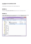
PC and double click “Setup.exe” 4. Click “Next” button.
2. Click “Next” button.
5. Confirm license agreement and check
ON “I Agree”. Then “Next” button will be
enabled. Click “Next” button
3. Click “Next” button.
6. Click “Next” button.
1
ScanMaster Field 7. Following display will appear. Please
wait a few minutes.
10. Click “Finish” button. Screen “7” is
displayed
8. Following display will appear. Click
“Next” button.
11. Click “Close” button.
9. Click “Install” button.
12. Following icon
desktop of tablet PC.
will
be
added
on
2
ScanMaster Field SCREENS Current scan position name
Current project name
MAIN SCREEN This is MAIN screen of ScanMaster Field. Buttons: #2 #1
#3 #4
#1: NEW (PROJECTS): Create a new project. #2: LIST (PROJECTS): Select and edit to existing projects. #5 #6
Please refer to also “Func 5. Project Management”. #3: NEW (SCAN POSITIONS): Create a new scan position. #4: LIST (SCAN POSITIONS): Select and edit existing scan position. #7
#13
#8
#9 #14 #11
#10 #12
#16
#15 Please refer to also “Func 6. Scan Position Management”. #5: OCC & BS: Set occupied point and back sight point. #6: RESULTS: Check back sight accuracy by difference between back sight point coordinate and target scan result. #7: NEW (SCAN & IMAGES): Create a new scan and take panoramic image of specified region. #8: LIST (SCAN & IMAGES): Check and edit to existing region (scan and panoramic image). #9: NEW (TARGETS): Create a new target scan. #10: LIST (TARGETS): Check and edit to existing target scan. #11: NEW (OBSERVATION): Create a new target scan. #12: LIST (OBSERVATION): Check and edit to existing point. #13: CLOSE: Close current project. #14: UNITS: Change project unit. See also “Func 1. Set System Unit”. #15: DEVICE: Check GLS status. See also “Func 2”, “Func 3” and “Video Screen” of “Screens”. #16: VIEW: Show the last captured data. See also “Sphere Screen” and “Cube Screen”. VIDEO SCREEN Video screen is shown when set scan region, target scan and observation. USB connection is faster than WLAN connection for getting higher video frame rate. Some buttons differ due to current status. Arrow button is used for turning to aiming direction. Also by clicking on the video, GLS turns to clicked direction. SETTING button is used for video setting. Please see also “Func 5. Change Video Quality And Zoom”. When click JOG button, video disappears, then jog dial of GLS is enabled to aim with peepsight. 3
ScanMaster Field SPHERE SCREEN This SPHERE screen is used for setting region of capturing scans, images, target scans, observations and checking the results. Some buttons are not displayed due to current status. Buttons: DISPLAY: Show/Hide display items. See also “Func17 Show/Hide Display Item”. EXTENTS: Show overall range of data. SWIVEL: Set to Swivel mode. ZOOM: Set to Zoom mode. Up and Down Arrow button: Zoom up and down. Left and Right Arrow button: Change display to next region of same scan position. SPHERE: Change display to Sphere view. Data are shown by the viewpoint of scanner. CUBE: Change display to Cube view. Data can be rotated in display. CLOSE: Close this screen. CUBE SCREEN This CUBE screen is used for checking scan result. Buttons: DISPLAY: Show/Hide display items. See also “Func17 Show/Hide Display Item”. EXTENTS: Show overall range of data. PAN: Set to Pan mode. ORBIT: Set to Orbit mode. ZOOM: Set to Zoom mode. Up and Down Arrow button: Zoom up and down. Left and Right Arrow button: Change display to next region of same scan position. CLOSE: Close this screen. 4
ScanMaster Field 1. START UP Double‐click “ScanMaster Field” icon on desktop. The screen that is shown first differs by the status of the last work. Pattern1: No project exists (ex. The first time of start‐up) (1) CREATE PROJECT screen (1‐1) will be displayed firstly. Input project name and click OK. (2) CREATE SCAN POSITION screen (1‐2) will be displayed. Input name and click OK button. 1‐1. CREATE PROJECT Screen (3) MAIN screen (1‐3) will be displayed. Pattern2: The last project with no scan position exits (1) CREATE SCAN POSITION screen (1‐2) will be displayed. Input name and click OK button. (2) Main screen (Figure1‐3) will be displayed. # Current project is set lasted project automatically. Pattern3: The last project with scan positions exists (1) MAIN screen (Figure1‐3) will be displayed directly. 1‐2. CREATE SCAN POSITION screen
# Current project and scan position is set lasted one automatically. AUTHOR and DESCRIPTION are acceptable also in blank. To change project and scan position, please refer to “Func 5 Project Management” and “Func 6 Scan Position Management”. Project files are saved to under the directory “Documents\ScanMasterFieldProjects”. To open from PC ScanMaster, please copy all files under this directory to PC. 1‐3. MAIN Screen 5
ScanMaster Field 2. OCC & BS SETTING (ENABLE SKIP) If this procedure is skipped, occupation point is set as (X,Y,Z)=(0,0,0), instrument height is set to 0 and zero position of azimuth is set to the front of scanner. (1) Click OCC & BS button on MAIN screen. (2) OCCUPATION & BACKSIGHT screen (2‐1) will be displayed. #1 #2
#3 #4
#5 #6
2‐1. OCCUPATION POINT SETTING 2‐1. OCCUPATION & BACKSIGHT Screen
Set occupation point name. Following three ways can be done. Way 1: Direct input point name Input point name to edit box. The point must have a unique name. If an existing name is used, the OK button will be colored red and be disabled. Way 2: Create New Point (1) Click NEW button (#1) on OCCUPATION & BACKSIGHT screen. (2) CREATE POINT screen (2‐2) will be displayed. (3) Input point name and position coordinate. 2‐2. CREATE POINT Screen (4) Click OK button. Way 3: From List (1) Click LIST button (#2) on OCCUPATION & BACKSIGHT screen. (2) SELECT POINT screen (2‐3) will be displayed. (3) Select a point data and Click OK button. 2‐3. SELECT POINT Screen 2‐2. INSTRUMENT HEIGHT SETTING Set instrument height. Following two ways can be done. Way 1: Direct input value Input value to edit box. Way 2: Calculate from backsight Click CALCULATE FROM BACKSIGHT button on OCCUPATION & BACKSIGHT screen (2‐1). 6
ScanMaster Field 2‐3. SELECT TARGET FOR BACKSIGHT DIRECTION Set target for defining backsight angle. Way 1: Create New Target Scan And Set it (1) Click NEW button (#3) on OCCUPATION & BACKSIGHT screen (2‐1). (2) CREATE TARGET screen will be displayed. Input target name and click NEXT button. (3) VIDEO screen will be displayed. Aim to target direction and click OK button. Please refer to also “4. Target Scanning” Way 2: From List (1) Click LIST button (#4) on OCCUPATION & BACKSIGHT screen (2‐1). (2) SELECT TARGET screen will be displayed. Select a target and click OK button. 2‐4. SELECT POINT FOR BACKSIGHT COORDINATE Set target for defining backsignt angle. Way 1: Create New Target Scan And Set it (1) Click NEW button (#5) on OCCUPATION & BACKSIGHT screen (2‐1). (2) CREATE POINT screen will be displayed. Input point information and click OK button. For details of CREATE POINT function, please refer to “FUNC 7 Create New Point”. Way 2: From List (1) Click LIST button (#6) on OCCUPATION & BACKSIGHT screen (2‐1). (2) SELECT POINT screen will be displayed. Select a target and click OK button. 2‐5. APPLY SETTING PARAMETERS Click OK button on OCCUPATION & BACKSIGHT screen (2‐1). 7
ScanMaster Field 3. REGION SCANNING (1) Click NEW button of SCANS & IMAGES on MAIN screen. (2) CREATE SCAN AND IMAGES screen (3‐1) will be displayed. (3) Input region name and select a scan task from SCAN ONLY, IMAGES ONLY and SCAN+IMAGES. (4) Click NEXT button. 3‐1. CREATE SCAN AND IMAGES Screen
(5) SELECT AREA screen (3‐2) will be displayed. (6) Set a scan area. There are four ways to do that. Way 1: From Video #1
(1) Click AIM VIDEO + JOG button. (2) VIDEO screen (3‐3) will be displayed. #2
(3) Aim a point on video screen, then click LEFT, RIGHT, TOP or BOTTOM button. (4) When finished setting 4 angles of the region, Click OK button. Please refer to also “VIDEO screen” of “SCREENS”. 3‐2. SELECT AREA Screen Way 2: From Jog Dial (1) Click AIM VIDEO + JOG button. (2) VIDEO screen will be displayed. (3) Click JOG button. Video will be hidden. (4) Aim a point by peepsight of scanner, then click LEFT, RIGHT, TOP or BOTTOM button . (5) When finished setting 4 angles of the region, Click OK button. Way 3: From Panoramic Image If there is no panoramic image from current scan position, only spherical grid is shown. Please refer to also “Sphere Screen” of “Screens”. 3‐3. VIDEO Screen (1) Click AIM IMAGES button (#1) on SELECT AREA screen (3‐2). (2) Set the red square at the center of screen to Top‐left corner of scan region. (3) Click OK button. GLS will turn to specified direction and it returns to SELECT AREA screen (3‐2). (4) Click AIM IMAGES button (#2) on SELECT AREA screen (3‐2). (5) Set the red square at the center of screen to Bottom‐right corner of scan region. 3‐4. JOG Screen 8
ScanMaster Field (6) Click OK button. GLS will turn to specified direction and it returns to SELECT AREA screen (3‐2). Way 4: Direct input Input angle to edit box AZIMUTH and ZENITH. (7) Click NEXT on SELECT AREA screen (3‐2). (8) SELECT SCAN RESOLUTION screen (3‐5) will be displayed. (9) Set scan resolution by following three ways. 3‐5. SELECT SCAN RESOLUTION Screen
Way 1: By Distance (1) Select DISTANCE button. (2) Input horizontal and vertical resolution as distances in a surface at the specified range to surface. (3) Input distance to object. The range can be measured with GLS by pressing GET button. Way 2 : By Angle (1) Select ANGLE button. (2) Input horizontal and vertical resolution as angles. 3‐6. QUALITY SETTINGS Screen
Way 3 : By Points (1) Select POINTS button. (2) Input horizontal and vertical resolution as numbers of points. (10) Select zoom type from UNDER 50 and OVER 50. (11) If want to change SCAN QUALITY and IMAGE QUALITY, Click QUALITY button. QUALITY screen (3‐
6) will be displayed. Set type of those and click OK button. (12) Click NEXT button on SELECT SCAN RESOLUTION screen (3‐5). 3‐7. CONFIRMATION Screen (13) CONFIRMATION screen will be displayed. (14) Click START button. SPHERE screen (3‐8) will be displayed and the scan will start. For details of SPHERE screen, see also “Sphere Screen” of “Screens”. 3‐8. SPHERE Screen 9
ScanMaster Field 4. TARGET SCANNING (1) Click NEW button of TARGETS on MAIN screen. (2) CREATE TARGET screen will be displayed. (3) Input target name, rod height and search radius. (4) Click NEXT button. (5) VIDEO screen (4‐2) will be displayed. Aim to target by video or jog dial. (6) Click OK button. (7) SPHERE screen (4‐3) will be displayed and the target scan will start. For details of SPHERE screen, please refer also “Sphere Screen” of “Screens”. 4‐1. CREATE TARGET Screen 4‐3. SHERE Screen 4‐2. VIDEO Screen 10
ScanMaster Field 5. OBSERVATION (1) Click NEW button of OBSERVATIONS on MAIN screen. (2) CREATE POINT screen will be displayed. (3) Input point name. (4) Click OBSERVED button. Screen is changed to “5‐2. CREATE POINT (OBSERVED) screen”. (5) Click NEW button. (6) CREATE TARGET screen (5‐3) will be displayed. Input target name and click NEXT button. (7) VIDEO screen (5‐4) will be displayed. Aim to target by video or jog dial. 5‐1. CREATE POINT Screen (8) Click OK button. (9) SPHERE screen (5‐5) will be displayed and the target scan will start. For details of SPHERE screen, please refer to also “Sphere Screen” of “Screens”. 5‐2. CREATE POINT(OBSERVED) Screen
5‐3. CREATE TARGET Screen 5‐4. VIDEO Screen 5‐5. SHERE Screen 11
ScanMaster Field OTHER FUNCTIONS FUNC 1. SET SYSTEM UNIT (1) Click UNIT button from MAIN screen. (2) SET UNITS screen will be displayed. (3) Select units on each item. (4) Click OK. FUNC 2. CONNECT TO GLS (1) Click DEVICE button from MAIN screen. (2) DEVICE screen will be displayed. (3) Make sure GLS power is on. (4) Click CONNECTION button on DEVICE screen. (5) CONNECT TO DEVICE screen will be displayed. (6) Select the way of connection from WLAN and USB. Way 1: WLAN Firstly, a wireless connection between PC and GLS needs to be established. After that, input IP‐
address to IP ADRESS of GLS on CONNECT TO DEVICE screen and click OK button. The IP‐
address requires to be same with the setting of GLS. Way 2: USB Make sure GLS and tablet PC are connected with USB cable, then click OK button. Once Windows fall in standby mode and came back, USB connection may not be recovered. In this case, please once unplug the USB cable, and plug it again. To avoid this problem, please change setting of "System standby" or "System hibernates" to longer from Start‐>Control Panel‐>Power Options. We recommend to use USB connection because of connection stability. WLAN connection can be unstable by network environment. FUNC 3. CHECK BATTERY AND TILT STATUS (1) Click DEVICE button from MAIN screen. (2) DEVICE screen will be displayed. (3) Click STATUS button. (4) DEVICE STATUS screen will be displayed. If GLS is not connected, CONNECT TO DEVICE screen will be displayed. 12
ScanMaster Field FUNC 4. CHANGE VIDEO QUALITY AND ZOOM (1) Click SETTING button on VIDEO screen. (2) VIDEO SETTINGS screen will be displayed. (3) Select quality and zoom level. (4) Click OK button. FUNC 5. PROJECT MANAGEMENT (1) Click LIST button of PROJECTS on MAIN screen. (2) PROJECTS screen will be displayed. Buttons BACK : Go back to MAIN screen. NEW : Create new project. EDIT : Edit selected project. PROJECT EDIT screen will be displayed. Input new name and click OK. DELETE : Delete selected project. FOLDER : Change directory to list projects that were stored in it. OPEN : Open selected project. FUNC 6. SCAN POSITION MANAGEMENT (1) Click LIST button of SCAN POSITIONS on MAIN screen. (2) SCAN POSITIONS screen will be displayed. Buttons BACK : Go back to MAIN screen. NEW : Create new scan position. EDIT : Edit selected scan position. EDIT SCAN POSITION screen will be displayed. Input new name and click OK. DELETE : Delete selected scan position. OCCUPY : Change current scan position to selected one. 13
ScanMaster Field FUNC 7. CREATE NEW POINT Create a point by inputting name and XYZ coordinates manually. (1) Click NEW button on OCCUPATION & BACKSIGHT screen or Click NEW button of OBSERVATION on MAIN screen. (2) CREATE POINT screen will be displayed. (7‐1 or 7‐2) (3) Input point name and XYZ coordinates. (4) Click OK button. 7‐1. CREATE POINT Screen 7‐2. CREATE POINT Screen FUNC 8. CREATE NEW POINT FROM TARGET SCAN DATA Create a point from existing target data. (1) Click NEW button of OBSERVATION on MAIN screen. (2) CREATE POINT screen will be displayed. (8‐1) (3) Click OBSERVED button on CREATE POINT screen (8‐
1). Screen is changed to “8‐2. CREATE POINT (OBSERVED) screen”. (4) Input exist target name or click LIST button to select from target list. 8‐1. CREATE POINT Screen 8‐2. CREATE POINT (OBSERVED) Screen
14
ScanMaster Field FUNC 9. EDIT POINT (1) Click LIST button of OBSERVATION on MAIN screen. (2) POINTS screen will be displayed. (3) Select a point from list and click EDIT button. (4) EDIT POINT screen will be displayed. (5) Change point name and click OK button. FUNC 10. DELETE POINT (1) Click LIST button of OBSERVATION on MAIN screen. (2) POINTS screen will be displayed. (3) Select a point from list and click DELETE button. (4) WARNING screen will be displayed. (5) Click OK button. FUNC 11. IMPORT POINT FROM FILE (1) Click LIST button of OBSERVATION on MAIN screen. (2) POINTS screen will be displayed. (3) Click IMPORT button. IMPORT POINTS (11‐1) screen will be displayed. (4) Select types of separator and handling of name duplication. (5) Click NEXT button. (6) File Dialog will be displayed. (7) Select a file to import and click OPEN on File Dialog. 11‐1. IMPORT POINTS Screen (8) IMPORT POINTS screen (11‐2) will be displayed. (9) In Import column, check points to be imported. (10) Click "None‐Click To Set" to select data type for each column. (11) Click OK button. 11‐2. IMPORT POINTS Screen 15
ScanMaster Field FUNC 12. EXPORT POINT DATA TO FILE (1) Click LIST button of OBSERVATIONS on MAIN screen. (2) POINTS screen will be displayed. (3) Click EXPORT button. (4) File Dialog will be displayed. (5) Input file name of the file to be exported, and click SAVE button. FUNC 13. DELETE TARGET (1) Click LIST button of TARGETS on MAIN screen. (2) TARGETS screen will be displayed. (3) Select a target and click DELETE button. (4) WARNING screen will be displayed. (5) Click OK button. FUNC 14. EDIT TARGET (1) Click LIST button of TARGETS on MAIN screen. (2) TARGETS screen will be displayed. (3) Select a target and click EDIT button. (4) EDIT TARGET screen will be displayed. (5) Input new name and click OK button. FUNC 15. TARGET INFORMATION (1) Click LIST button of TARGETS on MAIN screen. (2) TARGETS screen will be displayed. (3) Select a target and click ETC button. (4) TARGET screen will be displayed. (5) Check detailed information of the target. 16
ScanMaster Field FUNC 16. CHECK TARGET (1) Click LIST button of TARGETS on MAIN screen. (2) TARGETS screen will be displayed. (3) Select a target and click VIEW button. (4) TARGET screen will be displayed. (5) Check detail of the target. FUNC 17. SHOW/HIDE DISPLAY ITEM (1) Click DISPLAY button on SPHERE screen. (2) DISPLAY SETTINGS screen will be displayed. (3) Click VISIBILITY button on DISPLAY SETTING screen. (4) VISIBILITY SETTING screen will be displayed. (5) Select data types to be shown. (6) Click OK button. FUNC 18. CHANGE APPEARANCE SETTINGS (1) Click DISPLAY button on SPHERE screen. (2) DISPLAY SETTINGS screen will be displayed. (3) Click VISIBILITY button on DISPLAY SETTING screen. (4) APPEARANCE SETTING screen will be displayed. (5) Select types for each item. (6) Click OK button. FUNC 19. CHECK SOFTWARE VERSION Click ScanMaster icon which is placed at the top‐left of screen. 17
ScanMaster Field User’s Manual
ScanMaster Field
http://www.topcon.co.jp
Please see the attached address list or the following website for contact addresses.
GLOBAL GATEWAY http://global.topcon.com/
©2011 TOPCON CORPORATION
ALL RIGHTS RESERVED