1
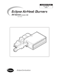
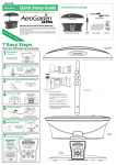
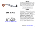
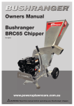
Info 140
11/4/03
ECLIPSE AIR HEAT BURNERS
Series “AH”, “DAH”, “TAH” & “CAH”
U.S. Reissue Pat. No. 26,244
Canadian Pat. No. 743,782
AH, Front View
Data 140-1
AH, Back View
Data 140-1
TAH
Data 140-3
CAH
Data 140-4
DAH, Blower Down
Data 140-2
WARNING
The burners covered in this Guide are designed to
mix fuel with air and burn the resulting mixture. All
fuel burning devices are capable of producing explosions and fires when improperly applied, installed,
adjusted, controlled, or maintained. This Guide will
provide information for using these burners for their
limited design purpose. Do not deviate from any in-
structions or application limits in this Guide without
written advice from the Eclipse Combustion Division
in Rockford, Illinois. Read this entire Guide before attempting to light burners. If you do not understand
any part of the information in this Guide, contact your
local Eclipse representative or Eclipse Combustion
before proceeding further.
Important Notices About Safe Burner Operation
Storage
Store the burner inside. Exposure to the elements can damage the burner.
Qualifications
Adjustment, maintenance, and troubleshooting of the mechanical parts of this
unit should be done by people with good mechanical aptitude and experience
with combustion equipment.
Replacement Parts
Order replacement parts from Eclipse only. Any customer-supplied valves or
switches should carry UL, FM, CSA, and/or CGA approval where applicable.
Operator Training
The best safety precaution is an alert and competent operator. Thoroughly instruct new operators so they demonstrate an adequate understanding of the
equipment and its operation. Regular retraining must be scheduled to maintain a
high degree of proficiency. The operator must have easy access to this Information Guide at all times.
1.0
Burner Operating Parameters & Requirements
Applications
Eclipse Air Heat Burners are line type burners ideal for generating large volumes of clean, hot air. Applications include ovens, dryers, fume incinerators, and
similar industrial equipment.
The “AH” models feature an integral combustion air blower mounted on the back
of the burner’s steel case. By supplying the correct air volume and pressure to
the burner, the blower allows stable operation over a wide range of duct velocities without installing a profile plate around the burner.
Capacities & Supply Pressures See Figure 2.
Burner Environment
Weather Protection: Protect burners from the weather.
Combustion Air: Must be free of contaminants. Eclipse strongly recommends
use of a combustion air filter to remove airborne particles. If corrosive fumes or
materials are present in the air, supply the blower with fresh, clean air from an
uncontaminated area of the plant.
Room Openings: If the burner is mounted on the side of the duct, provide at
least one square inch of opening to the outdoors for every 4000 Btu/hr (1.2 kW)
of burner firing rate. This will admit fresh combustion air.
Access: Provide access to the burner for inspection and maintenance.
Figure 1–Ignition, Flame Monitoring, and Pilot Components
Scanner Adaptor 109000
For Sizes through 400 AH
Flame Rod
#13093-3
Mounting
Bracket
Spark
Plug
#13047
Pilot Cock
#12659
Pilot
Regulator
#15027
Pilot Gas Inlet
1/4" N.P.T.
2
Mount In Place
of Peepsight
3/4"N.P.T.
Scanner
Connection
1/2" N.P.T.
Scanner Adaptor 109559
For Sizes 440 through 800 AH
Main Gas Inlet
2" N.P.T.
Peepsight
#10509
3/4" N.P.T.
Mount In Place
of Flame Rod
1/4"N.P.T.
Eclipse AirHeat v1.0 - Installation Guide No. 140, 11/4/03
Scanner
Connection
1/2" N.P.T.
Specifications
Input:
1,000,000 Btu/hr. per lineal foot (962 kW/m).
Fuels:
Natural gas or 100% propane vapor. Call Eclipse for information on using other fuels.
Gas Turndown:
40:1
Pilot Input:
Approximately 25,000 Btu/hr. (7.3 kW)
Gas Inlet Pressure:
800,000 Btu/hr/ft. (769 kW/m):
Nat. Gas:
Propane:
2.2" w.c.
0.9" w.c.
5.5 mbar
2.2 mbar
1,000,000 Btu/hr/ft. (962 kW/m):
Nat. Gas:
Propane:
3.5" w.c.
1.3" w.c.
8.7 mbar
3.2 mbar
Gas pressure shown is a differential measured between the gas inlet and a tap on
the duct wall 10" to 20" (254 to 508 mm) downstream of the burner.
Ambient Temp. Limits*:
– 40° to +104° F
Downstream Temp. Limits: 1500° F
– 40° to +40° C
815° C
Flame Length**:
800,000 Btu/hr. (769 kW/m):
1,000,000 Btu/hr. (962 kW/m):
28"
46"
0.71 m
1.17 m
Piloting:
Integral spark-ignited pilot; ignition plug included.
Flame Monitoring:
Flame rod supplied. UV scanner adaptors are available. For UV scanners, Eclipse
recommends a flame monitoring system that terminates the ignition spark and
proves the pilot flame without spark prior to opening the main gas valves.
CGA requires two flame rods on burners over 36" long (914 mm). Use a flame
monitoring endplate (see Data 140-6) to mount a second flame rod on the end opposite the gas inlet.
Motor:
Standard: 230/460/3/60 TEFC. Other motors can be supplied.
Materials:
All portions of the burner exposed to flame are cast iron or #321 stainless steel.
Emissions:
Emissions performance depends not only on the burner,
but also other factors such as chamber temperature, chamber design, and heat loading. For estimates of emissions performance in your application, call Eclipse.
Packaging Options:
Available with complete valve trains and control systems. AH burners and systems
can be supplied mounted on duct sections as specified by the customer. Call Eclipse
for information on custom packaged systems.
Models:
Model
Description
Data Sheet
AH
DAH
TAH
CAH
Line-shape, blower mounted on rear
Line-shape, blower mounted on bottom
“I”-shape, blower mounted on rear
Cross-shape, blower mounted on rear
Data 140-1
Data 140-2
Data 140-3
Data 140-4
Related Information:
Blower and motor specifications
Data 140-5
* Based on blower motor limitations.
** Based on parallel air flow. If mounted in a cross flow, then flame will be shorter.
CAUTION: It is dangerous to use any fuel burning equipment unless it is equipped with suitable flame sensing devices and automatic fuel shut-off valves. Eclipse can supply such equipment or information on alternate sources.
Eclipse AirHeat v1.0 - Installation Guide No. 140, 11/4/03
3
2.0
Control System Requirements
Turndown Method
Input is normally controlled by a motorized butterfly valve in the gas line to the
burner.
Regulator Loading Lines
Connect the top diaphragm chambers of the main gas and pilot gas regulators to the
duct approximately 10" downstream of the burner. This will allow the regulators to
maintain a constant supply pressure to the burner regardless of varying pressures in
the duct.
Piloting
Pilot gas flow is adjusted as shown in Figure 6.
Ignition
Ignition voltage should be 6000 VAC.
Check Valve
See Figure 3. At high fire, the gas pressure at the burner inlet is higher than the air pressure, and
the check valve is closed. At low fire, gas pressure falls below the air pressure, and the check
valve opens, permitting a small amount of air to mix with the gas. This premix at low fire stabilizes
the flame and helps distribute the flame evenly down the length of the burner.
w
Warning
Pressure Switch Connection
Do not install any valve or controlling device in the gas line between the
burner and the check valve tee, Figure 3. Because this section of the gas
line carries a partial pemix at low fire, it is possible under unusual conditions for the flame to travel back through the pipe to the tee. Devices installed in this section may be damaged and may melt, releasing gas to the
atmosphere and causing fires or explosions.
See Figure 4 for typical connection of combustion air and circulating fan limit
switches.
Limit Controls &Safety Equipment Limit controls and safety equipment should comply with current NFPA Standards* 86 and 86C, and all applicable local codes and/or standards.
*Available from:
National Fire Protection Association
Batterymarch Park
Quincy, MA 02269
Figure 3–Check Valve Operation
American National Standard Inst.
1430 Broadway
New York, New York 10018
Figure 4—Pressure Switch Location
Blower
Pressure Switch
WARNING!
Do Not Install Any Valves Here!
See Section 2.0
P
Tube at
Blower Inlet
Tee
Lo
Hi
Burner Air Tap
See Figure 7
Process Air
Gas Inlet
Manifold
Check Valve Opens When
Gas Inlet Pressure Is at Low Fire
4
P
Tube Points
Upstream
Hi
Lo
Circulating Air
Pressure Switch
Eclipse AirHeat v1.0 - Installation Guide No. 140, 11/4/03
Tube Points
Downstream
Figure 5–Mounting & Duct Lengths
In-Duct
Sealed
Slot-Fired
Duct Press: +0.2" to –0.5" w.c.
+0.5 to –1.2 mbar
Duct Press: 0" to –0.5" w.c.
0 to –1.2 mbar
Min./Max. Velocity: 500 to 6000 fpm
2.54 to 30.48 m/s
Optimum Velocity: 1000 to 4000 fpm
5.08 to 20.32 m/s
Min./Max. Velocity: 500 to 1200 fpm
2.54 to 6.10 m/s
Min./Max. Velocity: 500 to 1200 fpm
2.54 to 6.10 m/s
• Provide at least 3" (76 mm) clearance between burner and top, bottom and sides of the duct.
• Profile plates are not required for
good burner operation, but uniform velocity must be maintained
for full length of burner. If velocity
is not uniform, profile plates can
be used to correct this condition.
Min./Max. Velocity: 500 to 1200 fpm
2.54 to 6.10 m/s
Min./Max. Velocity: 500 to 1200 fpm
2.54 to 6.10 m/s
Guidelines for All Mounting Arrangements
• Center the burner in the duct.
• Allow a minimum of 46" (1168 mm) from burner to nearest point
of possible flame impingement at an input of 1,000,000 Btu/hr.
(962 kW/m).
Min./Max. Velocity: 500 to 6000 fpm
2.54 to 30.48 m/s
• On burners longer than 36" (914 mm), use a hanger or a pedestal to support the blower and motor.
Optimum Velocity: 1000 to 4000 fpm
5.08 to 20.32 m/s
Duct Lengths
Minimum Distance Before Transition
Rectangular Ducts: One Height or Width, Whichever is Greater
Round Ducts: One Diameter
7.5°
Maximum
Air Flow
AH
Burner
Minimum Distance Before
Possible Flame Impingement = 46"
Eclipse AirHeat v1.0 - Installation Guide No. 140, 11/4/03
5
3.0
Duct Design and Burner Mounting
Duct Design
See Figure 5 for typical mounting arrangements and duct designs.
Support
The mounting flange or brackets supplied with an AH burner are capable of supporting the weight of the burner and blower. The AH burner case itself is designed to support the weight of the blower, so the blower does not require independent support.
Valve Train Support
Support valve trains independently of the burner.
Gas Piping
Use flexible nipples to allow for thermal expansion of the burner.
Check Valve Piping
Gas flow through the check valve must be horizontal. See Figure 3.
Gas Piping Standards
Gas piping must comply with American National Standard entitled “National Fuel
Gas Code”* (NFPA No. 54 or ANSI Z223.1), or must be acceptable to the authority having jurisdiction.
Wiring Standards
Electrical wiring must comply with the National Electric Code*, (NFPA Std. 70 or
ANSI-CI 1981), or must be acceptable to the authority having jurisdiction.
*Available from:
National Fire Protection Association
Batterymarch Park
Quincy, MA 02269
4.0
American National Standard Inst.
1430 Broadway
New York, New York 10018
Start-Up And Adjustment
Initial Settings
Adjust the linkage of the gas control valve so that when heat is called for, the
valve is 10° from fully open, and when cooling is required, the valve is approximately 5° from fully closed.
Close all manual gas cocks.
With the pilot cock handle in the closed position, remove the top screw and turn
the adjusting screw five turns out from fully closed. See Figure 6.
Start Blower
Start the combustion air blower on the burner. Check the rotation to make sure it
is correct. If not, have a qualified electrician rewire the blower for proper rotation.
Start Circulating Fan
Start the duct circulating fan.
Figure 6–Pilot Cock
Handle
(Shown in
Open Position)
Figure 7–Pressure Measurement
Top Screw
Air Pressure
Taps (2)
Gas
Pressure
Tap
Duct Tap
10" to 20"
Downstream of Burner
Adjusting Screw
(Clockwise for less pilot gas,
Counterclockwise for more pilot gas)
6
Eclipse AirHeat v1.0 - Installation Guide No. 140, 11/4/03
4.0
Start-Up And Adjustment (cont’d.)
Set Air Pressure Drop
Measure the air pressure drop across the burner as shown in Figure 7.
Turn the disc on the blower air inlet until the air pressure drop is between 0.4"
w.c. minimum and 1.0" w.c. maximum. For a given input, lower air pressure
drops will produce a longer flame, and higher drops will produce a shorter flame.
Large Burners Only: Some models, such as the 640, 680, and 720 TAH burners, contain a butterfly valve in the check valve line as shown in Figure 8. On
these models, after setting the air flow as described in the previous paragraph,
measure the air pressure drop between the gas pressure tap and duct as shown
in Figure 7. Gas flow must be off. Adjust the butterfly valve to produce an air
pressure drop of 0.2" w.c.
Start Spark
Set Pilot Flow
Energize the ignition spark. Do not touch
the ignition rod, ignition wire, or transformer while the spark is energized, or
you will get a shock.
Open all pilot gas valves, including the
handle of the pilot cock, Figure 6. The pilot
should light.
Figure 8–Butterfly
in Check Valve Line
Butterfly Valve On
640, 680 & 720
TAH Burners
Check
Valve
Turn the pilot adjusting screw to produce a
bushy blue flame that provides a flame
monitoring signal strong enough to reliably
open the gas shut-off valves.
Set Gas Flow
Measure the gas differential pressure as
shown in Figure 7.
With the gas control valve at low fire, open
all main gas valves. The burner should
light with a stable, blue low fire flame that extends evenly down the burner
length.
Drive the control valve to high fire and adjust the gas adjusting valve to produce
a pressure drop that corresponds to the desired high fire rate, as shown in Fig. 1.
When setting high fire, be sure the flame does not impinge on anything downstream of the burner. To shorten the flame length for a given gas input, increase
the air pressure drop as described above.
Check All Settings
5.0
Return the burner to low fire and check to be sure that the burner remains lit with
a stable flame that extends down the burner length. Cycle the burner between
low and high fire several times, checking pressure drops and flame lengths.
Routine Maintenance
Motor Lubrication
Oil the blower motor according to the manufacturer’s instructions as printed on
the motor label.
Ignition Plug/Flame Rod
Ignition plugs and flame rods wear out over long periods of normal burner operation. Eclipse recommends that the user keep at least one of each in stock at all
times to prevent nuisance shutdowns.
Eclipse AirHeat v1.0 - Installation Guide No. 140, 11/4/03
7
6.0
Trouble-Shooting
Symptom
1. Burner does not
start initially.
Cause
a) Air pressure switches
not making.
Check
Remedy
b) Faulty pressure
switches.
a) Check pressures in
duct at location of
switch connections.
b) Check electrical
portion of switch.
a) Change pressure
connections where
a more positive
pressure is present.
2. Burner kicks out
shortly after start-up.
a) Low gas pressure
switch set too high.
a) Check low pressure
switch setting.
a) Reset
3. Pilot will not ignite on
initial light-off.
a) Raw gas fed into pilot
causing carbon hair on
spark plug.
a) Check spark plug for
carbon hair; also check
gap on plug (should be
3/64" - 3/32".
a) Adjust pilot gas cock by
first screwing needle
closed, then with transformer powered, open
needle slowly 1/4 turn
at a time.
4. Flame failure when
burner goes to high fire.
a) Gas pressure to pilot
regulator too high.
a) Check pilot gas pressure
to regulator (should be
1 PSIG maximum).
b) Check tightness of bolts.
a) Relocate pilot gas line or
use second pilot
regulator.
b) Tighten bolts.
c) Clean impulse line of any
dirt particles and relocate
duct connection to transmit maximum duct
pressure.
d) Clean check valve.
b) Bolts which fasten pilot
casting to burner are not
tight enough.
c) Pilot regulator not reacting fast enough to duct
pressure changes.
d) Check valve stuck open.
e) Too much pilot gas.
c) Check impulse line for
possible dirt clogging;
also check impulse line
duct connection to
determine if an effective
pressure is being transmitted to regulator.
e) Reduce pilot gas flow.
5. Flame failure when main
burner returns from high
to low fire.
a) Gas pressure to pilot
regulator.
b) Under-gassing pilot.
a) See Check 4a.
a) See Remedy 4a.
b) Check pilot regulator
inlet and outlet gas
pressures; also check
pilot flame.
c) See Check 4c.
b) Open needle on pilot
adjusting cock slowly
1/4 turn at a time.
6. Main flame too large at
high fire.
a) Gas pressure too high
at burner inlet.
a) Check gas pressures.
b) Combustion air pressure
too low.
b) Check air pressure
differential.
c) Check valve stuck open.
7. Main flame not
extending beyond face
of burner at high fire.
a) Air pressure
differential too high.
b) Burner not firing rated
input.
c) Burner gas holes
plugged.
8. Main flame long and
yellow.
Info 140 11/4/03
a) Velocity past burner
lower than 500 FPM.
b) Check valve stuck open.
c) See Remedy 4c.
a) Screw out on main gas
pressure regulator.
Adjust linkage on gas
control valve to hold
valve less than full open
when at high fire.
b) Open air shutter on
makeup air blower.
c) Clean check valve.
a) Check air pressure
differential between
combustion air manifold
and main duct.
b) Check gas pressure
differential.
c) Check gas holes for dirt
or lint.
a) Close air shutter on
makeup air blower.
b) Screw in on main gas
pressure regulator to
provide more gas.
c) Clean gas holes with #42
MTD drill. Clean air
holes with #27 MTD
drill.
a) Check velocities and
rotation of main
circulating fan.
a) Open shutter on
makeup air blower.
b) Clean check valve.