1
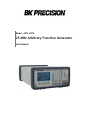
Model: 4075, 4078
25 MHz Arbitrary Function Generator
USER MANUAL
SERVICE INFORMATION
Warranty Service: Please go the support and service section on our website www.bkprecision.com to obtain a RMA #. Return the
product in the original packaging with proof of purchase to the address below. Clearly state on the RMA the performance problem and
return any leads, probes, connectors and accessories that you are using with the device.
Non-Warranty Service: Please go the support and service section on our website www.bkprecision.com to obtain a RMA #. Return the
product in the original packaging to the address below. Clearly state on the RMA the performance problem and return any leads, probes,
connectors and accessories that you are using with the device. Customers not on an open account must include payment in the form of a
money order or credit card. For the most current repair charges please refer to the service and support section on our website.
Return all merchandise to B&K Precision Corp. with pre-paid shipping. The flat-rate repair charge for Non-Warranty Service does not
include return shipping. Return shipping to locations in North America is included for Warranty Service. For overnight shipments and
non-North American shipping fees please contact B&K Precision Corp.
B&K Precision Corp.
22820 Savi Ranch Parkway
Yorba Linda, CA 92887
www.bkprecision.com
714-921-9095
Include with the returned instrument your complete return shipping address, contact name, phone number and description of
problem.
LIMITED THREE-YEAR WARRANTY
B&K Precision Corp. warrants to the original purchaser that its products and the component parts thereof, will be free from defects in
workmanship and materials for a period of three years from date of purchase.
B&K Precision Corp. will, without charge, repair or replace, at its option, defective product or component parts. Returned product must
be accompanied by proof of the purchase date in the form of a sales receipt.
To obtain warranty coverage in the U.S.A., this product must be registered by completing a warranty registration form on our website
www.bkprecision.com within fifteen (15) days of purchase.
Exclusions: This warranty does not apply in the event of misuse or abuse of the product or as a result of unauthorized alterations
or repairs. The warranty is void if the serial number is altered, defaced or removed.
B&K Precision Corp. shall not be liable for any consequential damages, including without limitation damages resulting from loss of use.
Some states do not allow limitations of incidental or consequential damages. So the above limitation or exclusion may not apply to you.
This warranty gives you specific rights and you may have other rights, which vary from state-to-state.
B&K Precision Corp.
22820 Savi Ranch Parkway
Yorba Linda, CA 92887
www.bkprecision.com
714-921-9095
2
Safety Summary
The following safety precautions apply to both operating and maintenance personnel and must be
observed during all phases of operation, service, and repair of this instrument. Before applying power,
follow the installation instructions and become familiar with the operating instructions for this
instrument.
Failure to comply with these precautions or with specific warnings elsewhere in this manual violates
safety standards of design, manufacture, and intended use of the instrument. B&K PRECISION
assumes no liability for a customer’s failure to comply with these requirements. This is a Safety Class I
instrument.
GROUND THE INSTRUMENT
To minimize shock hazard, the instrument chassis and cabinet must be connected to an electrical
ground. This instrument is grounded through the ground conductor of the supplied, three-conductor ac
power cable. The power cable must be plugged into an approved three-conductor electrical outlet. Do
not alter the ground connection. Without the protective ground connection, all accessible conductive
parts (including control knobs) can render an electric shock. The power jack and mating plug of the
power cable meet IEC safety standards.
DO NOT OPERATE IN AN EXPLOSIVE ATMOSPHERE
Do not operate the instrument in the presence of flammable gases or fumes. Operation of any electrical
instrument in such an environment constitutes a definite safety hazard.
KEEP AWAY FROM LIVE CIRCUITS
Instrument covers must not be removed by operating personnel. Component replacement and internal
adjustments must be made by qualified maintenance personnel. Disconnect the power cord before
removing the instrument covers and replacing components. Under certain conditions, even with the
power cable removed, dangerous voltages may exist. To avoid injuries, always disconnect power and
discharge circuits before touching them.
DO NOT SERVICE OR ADJUST ALONE
Do not attempt any internal service or adjustment unless another person, capable of rendering first aid
and resuscitation, is present.
DO NOT SUBSTITUTE PARTS OR MODIFY THE INSTRUMENT
Do not install substitute parts or perform any unauthorized modifications to this instrument. Return the
instrument to B&K Precision for service and repair to ensure that safety features are maintained.
WARNINGS AND CAUTIONS
WARNING and CAUTION statements, such as the following examples, denote a hazard and appear
throughout this manual. Follow all instructions contained in these statements.
A WARNING statement calls attention to an operating procedure, practice, or condition, which, if not
followed correctly, could result in injury or death to personnel.
A CAUTION statement calls attention to an operating procedure, practice, or condition, which, if not
followed correctly, could result in damage to or destruction of part or all of the product.
WARNING:
Do not alter the ground connection. Without the protective ground connection, all
accessible conductive parts (including control knobs) can render an electric shock.
The power jack and mating plug of the power cable meet IEC safety standards.
WARNING:
To avoid electrical shock hazard, disconnect power cord before removing covers.
Refer servicing to qualified personnel.
3
CAUTION:
Before connecting the line cord to the AC mains, check the rear panel AC line
voltage indicator. Applying a line voltage other than the indicated voltage can
destroy the AC line fuses. For continued fire protection, replace fuses only with
those of the specified voltage and current ratings.
CAUTION:
This product uses components which can be damaged by electro-static discharge
(ESD). To avoid damage, be sure to follow proper procedures for handling, storing
and transporting parts and subassemblies which contain ESD-sensitive
components.
4
Table of Contents
Safety Summary .............................................................................................. 3
Section 1 .......................................................................................................... 1
Introduction ........................................................................................................................ 1
1.1
1.2
1.3
1.4
Introduction .............................................................................................................................................. 1
Description ............................................................................................................................................... 1
Memory Architecture ............................................................................................................................... 1
Package Contents ................................................................................................................................... 2
Specifications..................................................................................................................... 2
Modulation Combinations ................................................................................................. 4
Section 2 .......................................................................................................... 5
Installation .......................................................................................................................... 5
2.1 Introduction .............................................................................................................................................. 5
2.2 Mechanical Inspection ............................................................................................................................. 5
2.3 Initial Inspection ....................................................................................................................................... 5
2.4 Instrument Mounting ................................................................................................................................ 5
2.5 Product Dimensions ................................................................................................................................ 5
2.6 Power Requirements ............................................................................................................................... 5
2.7 Grounding Requirements ........................................................................................................................ 6
2.8 Signal Connections .................................................................................................................................. 6
2.9 RS-232 Connection ................................................................................................................................. 6
2.10 RS-232 Configuration ............................................................................................................................. 7
2.11 GPIB Address ......................................................................................................................................... 7
2.12 GPIB Connections (Optional) ................................................................................................................ 7
Section 3 .......................................................................................................... 9
Operating Instructions ...................................................................................................... 9
3.1 General Description ................................................................................................................................. 9
3.2 Display Window .................................................................................................................................... 10
3.3 Front Panel Controls .............................................................................................................................. 11
3.4 Back Panel Controls .............................................................................................................................. 11
3.5 Output connectors ................................................................................................................................. 12
3.6 MENU Keys ........................................................................................................................................... 12
3.7 ON Key .................................................................................................................................................. 28
3.8 Cursor Movement Keys ......................................................................................................................... 28
3.9 Rotary Input Knob .................................................................................................................................. 28
3.10 Power-On Settings .............................................................................................................................. 28
3.11 Memory ................................................................................................................................................ 29
3.12 Displaying Errors ................................................................................................................................. 29
3.13 Using Model 4075 and 4078................................................................................................................ 30
3.14 Examples ............................................................................................................................................. 30
Section 4 ........................................................................................................ 34
Programming.................................................................................................................... 34
4.1
4.2
4.3
4.4
Overview ................................................................................................................................................ 34
Device State .......................................................................................................................................... 35
Interface Function Subsets .................................................................................................................... 35
Device Address...................................................................................................................................... 35
5
4.5 Message Exchange Protocol ................................................................................................................. 36
4.6 Block Data (GPIB Only) ......................................................................................................................... 37
4.7 Instrument Identification ........................................................................................................................ 37
4.8 Instrument Reset ................................................................................................................................... 37
4.9 Self Test................................................................................................................................................. 37
4.10 Command Syntax ................................................................................................................................ 37
4.11 Status Reporting .................................................................................................................................. 41
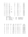
4.12 Common Commands ........................................................................................................................... 45
4.13 Instrument Control Commands............................................................................................................ 49
4.14 IEEE 488.1 Interface Messages .......................................................................................................... 77
4.15 SCPI Command Tree .......................................................................................................................... 77
4.16 Block Transfer (GPIB only) .................................................................................................................. 82
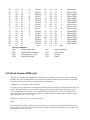
4.17 GPIB Communication Protocol ............................................................................................................ 83
Section 5 ........................................................................................................ 87
Performance Check Procedures..................................................................................... 87
5.1 Introduction ............................................................................................................................................ 87
5.2 Test Equipment..................................................................................................................................... 87
5.3 Performance Tests ............................................................................................................................... 88
6
Section 1
Introduction
1.1 Introduction
This manual contains information required to operate, program and test the Model 4075 and 4078 – 25 MHz DDS
Arbitrary Function Generators. This section covers the instrument general description, instrument specifications and
characteristics.
1.2 Description
The Model 4075 and 4078 are versatile high performance arbitrary waveform generators. Arbitrary waveforms can be
programmed and generated with 14 bit resolution and up to 400,000 points length. Waveforms can be output in
continuous, triggered, gated or burst mode. AM and FM modulation combined with versatile Sweep capabilities make
the unit suitable for a wide range of applications. Editing is flexible and easy including auto increment, line draw and
predefined waveform facilities. The instrument can be remotely operated via the RS232 or an optional GPIB interface
(order models 4075GPIB or 4078GPIB) and they are SCPI compatible.
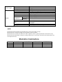
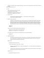
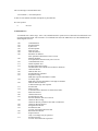
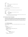
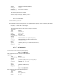
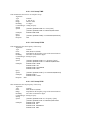
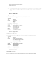
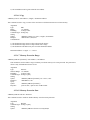
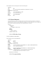
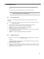
1.3 Memory Architecture
The waveform memory consists of 400,000 points. The user can edit arbitrary waveforms in waveform memory and can
specify any data value in the range from -8191 to 8191 for any point in waveform memory (14 bit depth). Due to their
large memory bank, the 4075 and 4078 can essentially give the user greater freedom in selecting the size of their
waveforms and the number of waves they desire to generate, with the limit of 400,000 total points when added together.
For example, these generators can create a waveform with 10,000 points, another waveform with 50,000 points, a third
waveform with 40,000 points, and a fourth waveform with 300,000 points. These four waveforms total up to 400,000
points, but essentially they can be referenced in the memory bank according to their starting point and their length.
There are no restrictions as to how many different waveforms you can store in the memory, so as long as the sum of the
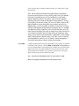
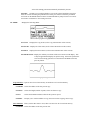
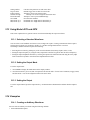
points of all the waveforms do not exceed 400,000 points. To better illustrate this, refer to drawing below:
Waveform 1
Point
A pts.
Waveform 2
Waveform 3
B pts.
C pts.
1
Waveform …
D pts.
Point
400,000
A pts. + B pts. + C pts. + D pts. ≤ 400,000 pts.
The following operations can be performed in the waveform memory:
- Insert and scale any of the following predefined waveforms:
o Sine
o Triangle
o Square
o Ramp up
o
o
Ramp down
Noise
- Draw a line between any two points
- Clear (set to zero) any set of points or all points
- Set individual point values
After specifying a section of waveform memory for execution, the following parameters of the waveform can be
configured:
- Point rate (frequency)
- Peak-to-peak amplitude
- Offset voltage
1.4 Package Contents
The following list of items and accessories come in the package:
1.
2.
3.
4.
4075 or 4078 DDS Function Generator
AC power cord
CD containing user manual and waveform creation software Wave-X
RS232 Serial Cable
Specifications
Models
Channels
Frequency
Characteristics
Sine
Square
Triangle, Ramp
Pulse
Accuracy
Resolution
Built-in Waveforms
Arbitrary
Characteristics
Waveform Length
Vertical Resolution
Noise
Sampling Rate
Frequency Accuracy
Frequency Resolution
Amplitude Range
Amplitude Resolution
Amplitude Accuracy (at 1 kHz)
Flatness (relative to 1 kHz)
Output
Characteristics
Offset Range
Offset Resolution
Offset Accuracy
Output Impedance
Output Protection
4075
4078
1 Channel
2 Channels
1 uHz to 25 MHz
1 µHz to 25 MHz
1 µHz to 5 MHz
1 mHz to 10 MHz
0.002 % (20 ppm)
12 digits or 1 µHz
Sine, Triangle, Square, Noise, Ramp Up, Ramp Down,
Sine(X)/X, Exponential Up, Exponential Down,
Gaussian
2 points to 400,000 points
14 bits (16,384 levels)
Add 1% to 100% to output waveform
100 MSa/s, Point execution rate: adjustable from 10 ns
to 50 s
0.005% (50 ppm)
4 digits
10 mV to 10 Vp-p into 50 ohms
3 digits (1000 counts)
± 1% ± 1 mV
± 0.2 dB to 1 MHz
± 1 dB to 25 MHz
± 5 V into 50 Ω, depending on the Amplitude setting
10 mV with 3 digits resolution
± 1% ± 10 mV into 50 Ω
50 Ω typical
The instruments output is protected against short
circuit or nominal accidental voltages applied to the
main output connector
Output Leakage
Total Harmonic Distortion (sine)
Spurious (sine)
Rise/Fall Time (square, pulse)
Waveform
Characteristics
Variable Duty Cycle
Variable Symmetry
Symmetry at 50%
Linearity (triangle, ramp)
Pulse Width
(period 10 μs - 0.1 μs)
Variable Edge Time
(period 100 μs - 0.16 μs)
Continuous
Triggered
Operating Modes
Gate
Burst
Phase
Trigger Source
Modulation
Characteristics
Amplitude
Modulation
Frequency
Modulation
Sweep
Characteristics
Internal
External
Internal
External
Sweep Shape
Sweep Time
Sweep Trigger
Trigger IN
Sync OUT
Inputs and
Outputs
Modulation IN
Marker Out
Reference IN-OUT
Approximately 10 mA can be present at the output
BNC connector when unit is powered on and the
output is off
DC-20 kHz, -65 dBc
20 kHz-50 kHz, -60 dBc
50 kHz-100 kHz, -50 dBc
100 kHz-10 MHz, -45 dBc
10 MHz-25 MHz, -35 dBc
DC-1 MHz
< -60 dBc
< 12 ns (10% to 90%) at full amplitude into 50 Ω
20% to 80% to 5 MHz (square)
40% to 60% to 10 MHz (square)
50% >10 MHz (square))
10%-90% to 5 MHz (triangle)
< 1 % + 5 ns
<0.1% of peak output (1 µHz to 250 kHz)
20 ns to < ( Period -20 ns )
(10 ns resolution)
100 ns to Width/0.625 (50 % duty cycle)
10 ns resolution
Output continuous at programmed parameters
Output quiescent until triggered by an internal or
external trigger, then one waveform cycle is generated
to programmed parameters. Up to 10 MHz trigger rate
for ARB waveforms and 5 MHz in DDS mode
Same as triggered mode, except waveform is executed
for the duration of the gate signal. The last cycle
started is completed
2-999,999 cycles
-360.0 to +360 degrees with 0.1 degree resolution
Trigger source may be internal, external or manual.
Internal trigger rate 0.01 Hz-1 MHz (1 µs – 100 s)
0.1 Hz-20 kHz sine , square or triangle waveform
variable modulation from 0% to 100%
5 Vp-p for 100% modulation, 10 kΩ input impedance
0.01 Hz – 50 KHz bandwidth
0.1 Hz-20 kHz sine wave, square or triangle
5 Vp-p for 100% deviation, 10 kΩ input impedance,
0.01 Hz – 50 kHz bandwidth
Linear and Logarithmic, up or down
20 ms to 500 s
internal, external, continuous or burst
TTL Compatible
Maximum rate 10 MHz in ARB mode, 3 MHz in DDS
mode
Minimum width 50ns
TTL pulse at programmed frequency, 50ohms source
impedance
5 Vp-p for 100% modulation
10 KΩ input impedance
DC to >50 kHz minimum bandwidth
Positive TTL pulse user programmable in Arbitrary
waveform, 50 Ω source impedance
10 MHz, TTL compatible, input or output, for external
unit synchronization 50 Ω output impedance and 1 kΩ
input
Internal Trigger
General
Repetition
Resolution
Accuracy
Store Memory
Arbitrary Memory
Dimensions
Weight
Power
Temperature
Operating
Nonoperating
Humidity
EMC
Electrical Discharge Immunity
Safety Specifications
1 µs to 100 s
4 digits
+0.002%
50 full panel settings at power-off
400,000 points in flash memory
8.4(213) x 3.5(88) x 12(300) inches (mm) (WxHxD)
Approx. 3 kg
100 VAC-240 VAC ± 10%, 50 VA max.
0 ºC to +50 ºC
-20 ºC to +70 ºC
95 % RH , 0 ºC to 30 ºC
According to EN55011 for radiated and conducted
emissions
According to EN55082
According to EN61010 , CE approved
NOTE
Specifications listed in manual are applicable after a powered 30 minute warm-up
Specifications are verified according to the performance check procedures.
Specifications not verified in the manual are either explanatory notes or general performance characteristics only.
Specifications and information is subject to change without notice. For the most current and correct data please visit
www.bkprecision.com
Modulation Combinations
AM
FM
FSK
SINE
Yes
Yes
Yes
SQUARE
Yes
Yes
Yes
TRIANGLE
Yes
Yes
Yes
ARBITRARY
Yes
No
No
Section 2
Installation
2.1 Introduction
This section contains installation information, power requirements, initial inspection and signal connections for Model
4075 and 4078.
2.2 Mechanical Inspection
This instrument was carefully inspected before shipment. Upon receipt inspect the instrument for damage that might
have occurred in transit. If there is damage due to shipping, file a claim with the carrier who transported the unit. The
shipping and packing material should be saved if reshipment is required. If the original container is not to be used,
then use a heavy carton box. Wrap the unit with plastic and place cardboard strips across the face for protection. Use
packing material around all sides of the container and seal it with tape bands. Mark the box "FRAGILE".
2.3 Initial Inspection
After the mechanical inspection, verify the contents of the shipment (accessories and installed options). If the contents
are incomplete, or if the instrument does not pass the specification acceptance tests, notify the local service center.
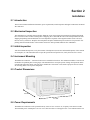
2.4 Instrument Mounting
The Model 4075 and 4078 - Function Generators are intended for bench use. The instrument includes a front feet tilt
mechanism for optimum panel viewing angle. The instrument does not require special cooling when operated within
conventional temperature limits. The unit can be installed in a closed rack or test station if proper air flow is assured
for removing about 15 W of power dissipation.
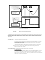
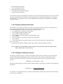
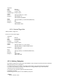
2.5 Product Dimensions
88 mm
300 mm
213 mm
2.6 Power Requirements
The Model 4075 and 4078 can be operated from any source of 90 V to 264 V AC, frequency from 48 Hz to 66 Hz.
The maximum power consumption is 50 VA. Use a slow blow fuse UL/CSA approved of 1 A as indicated on the rear
panel of the instrument.
The instrument power fuse is located in the AC input plug. To access the fuse, first disconnect the power cord and
then remove the fuse cartridge.
2.7 Grounding Requirements
For the safety of operating personnel, the instrument must be grounded. The central pin on the AC plug grounds the
instrument when properly connected to the ground wire and plugged into proper receptacle.
WARNING
TO AVOID PERSONAL INJURY DUE TO SHOCK, THE THIRD WIRE EARTH GROUND MUST BE
CONTINUOUS TO THE POWER OUTLET. BEFORE CONNECTION TO THE POWER OUTLET,
EXAMINE ALL CABLES AND CONNECTIONS BETWEEN THE UNIT AND THE FACILITY POWER
FOR A CONTINUOUS EARTH GROUND PATH.
THE POWER CABLE MUST MEET IEC SAFETY STANDARDS.
2.8 Signal Connections
Use RG58U 50 Ω or equivalent coaxial cables for all input and output signals to and from the instrument.
2.9 RS-232 Connection
The rear panel RS-232 connector is a standard DB-9 male connector configured as a DCE. The pin assignments are
defined in the table below:
DB-9 pin
1
2
3
4
5
6
7
8
9
Name
TXD
RXD
GND
RTS
CRS
-
Note
Transmit Data
Receive Data
Signal ground
Request to Send
Clear to send
-
*Note: Use a Null-modem or cross over cable (pin 2 and 3 switched) in order to communicate with instrument. When
transmitting large files, use only RS232 to RS232 (female to female) cables with no more than 50FT in length. Baudrate
of 9600 and 19200 are recommended values when configuring the interface.
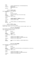
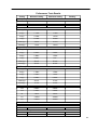
2.9.1 Communication Speed
The 4075 and 4078 have the capabilities of generating large arbitrary waveforms with up to 400,000 points. Due to
this nature, the time it takes to transmit these large waveforms may vary depending on the baudrate and cable used for
RS232 interface. As a general reference, provided below is a chart that shows the approximate amount of time it takes to
download or send the waveforms of the indicated sizes at the rated baudrate speed.
Number of data pts.
10,000 points
64,000 points
100,000 points
400,000 points
~1 min
~30 secs
~3 mins
~1 min 40 secs
~9 ½ mins
~6 mins 15 secs
~40+ mins
~26+ mins
Baudrates (bps)
9600
19200
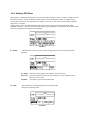
2.10 RS-232 Configuration
The instrument use 8 data bits, 1 stop bit, no parity and baud rate selectable from 2400 to 19.2K (2400, 4800,
9600, 19200). By default, the instrument is set at 9600-8-N-1.
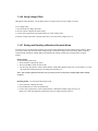
When the instrument is in remote mode, it will display the following screen:
This screen comes up whenever there is a transmission process, be it sending or receiving. To return to local mode
and exit this screen, simply press any front panel keys. Only do this when nothing is being transmitted or received
from a connected PC. In the case where a large waveform is being transmitted, please allow AT LEAST 15 seconds
or more after the PC software or program has finished sending BEFORE pressing a key to return to local mode.
The instrument requires this time to completely finish generating/transmitting the waveform.
2.11 GPIB Address
The instrument is shipped with the address set to decimal 9. The address can be changed from the front panel by using the
"UTILITY" menu.
2.12 GPIB Connections (Optional)
The rear panel GPIB connector is an AMPHENOL 57-10240 or equivalent, and connects to a standard IEEE-488 bus
cable connector. The GPIB line screens are not isolated from chassis and signal ground.
Section 3
Operating Instructions
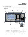
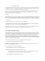
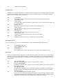
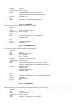
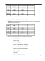
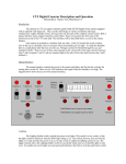
3.1 General Description
This section describes the displays, controls and connectors of the Model 4075 and 4078 - Function Generators.
All controls for the instrument local operation are located on the front panel. The connectors are located on both
front and rear panels.
4
9
10
2
5
6
7
1
12
3
14
13
8
16
15
11
7
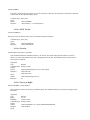
16
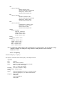
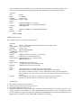
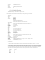
Figure 3.1 - Front Panel View
1.
2.
3.
Power ON-OFF
Display Window
FI-F4 Keys
4.
5.
Function Keys
Rotary Knob
(for Model 4075)
- Applies and removes AC power to the unit
- Displays all instrument data and settings on a LCD.
- Select the menu options that appear on the second line of the LCD display. Menus
differ depending on the selected parameter, function or mode.
- Select the output waveform, Sine, Triangle, Square, Pulse or Arbitrary.
- Used to increment/decrement numerical values or to scan through the possible
selections.
6.
Cursor Keys
- Used to move the cursor (when visible) to either left or right when modifying
values of various parameters.
7. Output ON
- Controls the main output signal. The output status is ON when lid.
8. Channel
- Selects the channel to configure (model 4078 only)
9. Numerical Keypad - Numeric entry keys for entering values for various functions and modes
10. Unit Setting Keys
- Quick keys for setting units for frequency, time, and amplitude
11. Enter Key
- Used for saving settings and numerical values
12. Mode Key
- Select from continuous, triggered burst, gate, or phase mode
13. Sweep Key
- Enters into the sweep menu to configure sweep settings
14. Modul Key
- Enters into the modulation menu for selecting modulation functions
15. Util Key
- Used for remote settings, system setup save/restore, and power settings.
16. Channel Output
- Dual BNC channel outputs (50 Ω) of function signals (model 4075 has CH1 only).
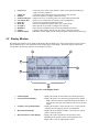
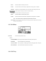
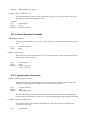
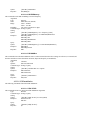
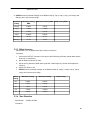
3.2 Display Window
The Model 4075 and 4078 have graphic LCD displays that can display up to 124 x 64 dots. When you power-on the
unit the SINE function is selected and its current settings appear in the display. The bottom displays a menu that
corresponds to the function, parameter or mode display selected.
1
2
6
3
5
4
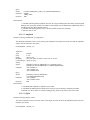
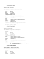
Figure 3.2 - LCD Display Screen
1.
2.
Channel Display
General Waveform Display
3.
Frequency/ Sweep Mode Display
4.
Menu Functions Display
5.
Menu Parameters Values Display
- Displays the current selected channel. (For model 4078 only)
- Displays the general waveform being generated in the channel.
Note: Waveform shown is approximated and scaled down. It
does not show the exact representation of the waveform at the
output.
- Displays the frequency values currently set to. In sweep mode,
it displays the sweeping type (Linear or Logarithmic).
- Displays the menu options available. Use F1-F4 keys on front
panel to select the options.
- Displays the values of parameters selected in the menu.
Depending on the options chosen, various parameters will
display with a cursor for adjusting their values.
6.
Mode Display
- Displays the current mode selected. The can be continuous,
trigger, burst, or gate (displayed as CONT , TRI, BURST, or
GATE respectively). Refer to section 3.6.2 for details.
3.3 Front Panel Controls
The front-panel controls select, display, and change parameter, function, and mode settings. They also include the keys
you use to program and generate arbitrary waveform output. Refer to Figure 3.1.
Use the rotary input knob and the cursor movement keys to enter data into the waveform generator.
To change a setting:
1. Press any FUNCTION keys (F1 – F4) that lead to a required item.
2. Move cursor using CURSOR keys to the appropriate position in the numeric field (if applicable).
3. Use the rotary input or the numerical KEYPAD to change the value of the displayed item. Changes take effect
immediately.
4. In some parameter settings, the ENTER key must be pressed in order to set their numerical/setting values.
Otherwise, it may not save.
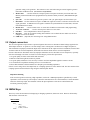
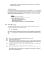
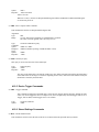
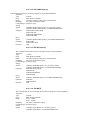
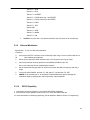
3.4 Back Panel Controls
The function generator has nine (five for model 4075) BNC Connectors on the rear panel where you can connect
coaxial cables. These coaxial connectors are labeled accordingly on the back panel for their respective channels and
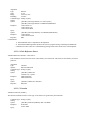
serve as carrier lines for input and output signals delivered to and from the function generator.
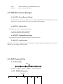
(For CH2 : Model
4078 only)
1
2
3
4
9
10
8
1
2
3
4
5
6
7
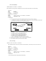
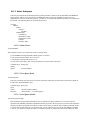
Figure 3.3 - Back Panel View
1.
2.
Modulation In - 5 Vp-p signal for 100% modulation, 10Kohms input impedance with DC - >20 KHz
bandwidth. This connector can be used for modulating external signals in AM and FM modulation.
Trig In - Use this connector to apply an external trigger or gate signal, depending on the waveform
generator setting, to the generator. This connector is also used when using an external signal to generate
FSK under modulation menu. (See section 3.6.8 for details)
3. Marker Out
- Use this connector to output a positive TTL pulse in Arbitrary waveform mode. The
Marker position and width can be programmed at any desired Arbitrary locations. (See section 3.6.3 for
details)
4. Sync Out - Use this connector to generate a positive TTL sync pulse output at each waveform cycle.
5. Ref In/Out - Use this connector to input a 10 MHz TTL signal to be used as a reference clock for the unit
signal generation. A 10MHz TTL level signal is available for synchronization of external units, when not
in External Reference mode.
6. RS-232 Port
- Used to connect to PC via serial cable for RS-232 serial interface and programming.
7. AC Power Connector
- Used to connect power cable to AC line source.
8. Fuse Box - Fuse compartment to check or replace fuse.
9. Rear Fan - Rear fan for internal cooling and ventilation. Do not block this area and be sure to leave
enough room for air to exhaust.
10. GPIB Port - (Optional) For connecting to PC using GPIB interface.
3.5 Output connectors
The waveform generator output circuits is protected against short circuit or nominal accidental voltages applied to the
main output connector . It operate as a 50 ohm voltage source working into a 50 ohms load. At higher frequencies,
non-terminated or improperly terminated output causes aberrations on the output waveform. In addition, loads less than
50 ohms reduce the waveform amplitude, while loads more than 50 ohms increase waveform amplitude.
Excessive distortion or aberrations caused by improper termination are less noticeable at lower frequencies, especially
with sine and triangle waveforms. To ensure waveform integrity, follow these precautions:
1. Use good quality 50 ohms coaxial cables and connectors.
2. Make all connections tight and as short as possible.
3. Use good quality attenuators if it is necessary to reduce waveform amplitudes applied to sensitive circuits.
4. Use termination or impedance-matching devices to avoid reflections.
5. Ensure that attenuators and terminations have adequate power handling capabilities.
If there is a DC voltage across the output load, use a coupling capacitor in series with the load. The time constant of the
coupling capacitor and load must be long enough to maintain pulse flatness.
Impedance Matching
If the waveform generator is driving a high impedance, such as the 1 MΩ input impedance (paralleled by a stated
capacitance) of an oscilloscope vertical input, connect the transmission line to a 50 Ω attenuator, a 50 Ω termination
and to the oscilloscope input. The attenuator isolates the input capacitance of the device and terminates the
waveform generator properly.
3.6 MENU Keys
These keys select the main menus for displaying or changing a parameter, function or mode. Below is the hierarchy
and selections of the menu tree.
MENU TREE
-
SINE
-
o
o
o
RAMP
FREQ
AMPL | OFST
INTREF | EXTREF
-
-
o
o
o
o
SQUARE
o
o
o
o
PULSE
o
o
o
o
-
FREQ
SYM
AMPL | OFST
INTREF | EXTREF
FREQ
SYM
AMPL | OFST
INTREF | EXTREF
FREQ
PULSE
FREQ | PERIOD
WIDTH
EQUAL EDGE
LEAD | TRAIL
AMPL | OFST
INTCLK | EXTCLK
ARB
o
o
FREQ | RATE
ARB
START | LENGTH
SAVE ARB
•
ABORT
MARK
•
ADDR
•
LENGTH
•
ON | OFF
•
PREV
EDIT
•
POINT
o
o
o
•
LINE
o
o
o
•
•
o
PREDEF
o
o
o
o
MORE
o
o
o
o
-
MODE
o
o
CONT
TRIG BURST
MAN
INT
•
EXT
ADRS
DATA
PREV
FROM
TO
EXEC
PREV
NO | YES
TYPE
FROM | DATA
LENGTH | SCALE
EXEC
NO | YES
COPY
CLEAR
FROM
LENGTH
TO
EXEC
•
NO | YES
FROM
TO
ALL
EXEC
•
PROT
FROM
TO
ALL
ON | OFF
SHOW WAVE
TRIG RATE
NO | YES
o
-
-
-
GATE
NBRST
MAN
INT
•
GATE RATE
EXT
o
PHASE (not available in ARB mode)
PHASE
SET-ZERO
PREV
SWEEP (not available in PULSE and ARB mode)
o
ON | OFF
o
START | STOP
o
RATE
o
LIN | LOG
MODUL
o
AM
ON | OFF
% | SHAPE
MOD. FREQ
EXT | INT
o
FM (not available in PULSE and ARB mode)
ON | OFF
DEV | SHAPE
MOD. FREQ
EXT | INT
o
FSK (not available in PULSE and ARB mode)
ON | OFF
F-HI | F-LO
RATE
EXT | INT
UTIL
o
RS232<
o
RECALL | STORE
o
POWER
3.6.1 WAVEFORM Keys
The keys select the waveform output and displays the waveform parameter menu (frequency, amplitude and offset).
When the Arbitrary waveform is selected, the display shows also the waveform rate.
Sine Menu
F1: FREQ
- (Frequency) Selects and displays the frequency. Change the frequency setting using the cursor
keys and rotary knob or numerical keypad. If a certain wavelength can't produce the waveform at
the desired frequency, the waveform generator displays an “Out of Range” error message.
F1: FREQ/RATE - Selects and displays the Point Rate (for Arbitrary Waveform mode only). The Rate parameter
governs the rate at which waveform points are executed, and thus the frequency of the waveform
output will also be affected. When you set this parameter, the waveform generator will keep that
execution rate for all waveform lengths until it is changed.
F3: AMPL/OFST - Selects the Amplitude or the Offset parameters.
In Arbitrary mode this setting defines the maximum peak-to-peak amplitude of a full-scale
waveform. If the waveform does not use the full scale of data (-8191 to +8191), then its actual
amplitude will be smaller.
Setting the Amplitude
The following equation represents the relative output amplitude voltage relationship between the frontpanel amplitude peak-to-peak setting and the data point values in waveform memory:
output voltage =
Amplitude p − p setting ⋅ data po int s value
+ offset
16382
Where 16382 is the total data point value range in waveform memory.
Examples
F3:OFST
F2:SYM
Front Panel
Amplitude
Setting
Data Point
Value
Relative Output
Amplitude Voltage
5 Vp-p
8191
+2.5 V
5 Vp-p
4095
+1.25 V
5 Vp-p
0
0V (offset voltage)
9 Vp-p
-4095
-4.5 V
4 Vp-p
-8191
-2 V
- Selects the Offset parameter. Change the offset by using the cursor keys, rotary dial or
numerical keypad. If a certain setting cannot be produced, the waveform generator will display a
“Setting Conflict” message.
- When the Square or Triangle waveforms are selected, the SYMMETRY option is available. Change
the symmetry by using the cursor keys, rotary dial or numerical keypad. If a certain setting cannot be
produced, the waveform generator will display a warning message.
Triangle Menu
F4: INTREF/EXTREF - Selects internal or external reference source for the generated standard waveforms
(the external reference must be connected to the rear panel Ref In connector).
3.6.2 MODE Key
Selects the output mode: CONT (Continuous), TRIG (Triggered), GATE (Gated), and BRST (Burst).
To select the output mode, press MODE, then press the function key that corresponds to the desired Mode menu
option, as shown:
Mode Menu
F1: CONT - (Continuous) - Selects continuous output.
F2: TRIG/BRST - (Triggered) - Triggers one output cycle of the selected waveform for each trigger event.
- (Burst) - Triggers output N cycles for each trigger event, where N ranges from 2 to 999,999.
F3: GATE - (Gated) - Triggers output cycles as long as the trigger source asserts the gate signal.
F4: PHASE - Selects the start phase of the signal in non-continuous modes. The range is from -360˚ to +360˚, with
a 0.1˚ resolution. In PHASE mode F2: SET-ZERO sets the phase reference to zero when few
instruments are connected to the same external reference and need to be synchronized with different
phase relations.
After selecting the TRIG , GATE or BURST menu, the trigger source menu is available:
Trigger Menu
F1: MAN - Selects manual as the trigger source. To trigger the waveform generator,
press this MAN TRIG again.
F2: INT
- Selects the internal trigger generator as the trigger source. Change the
internal trigger rate displayed with the rotary input knob.
F3: EXT
- Selects the external trigger signal as the trigger source. The trigger source
is supplied through the TRIG IN connector.
F4: NBRST - Selects the number of burst pulses to be output with each trigger. The N can be changed from 2 to
999,999.
3.6.3 ARBITRARY Key
When selected displays the following screen:
Arbitrary Menu
F1: FREQ/RATE
F2: ARB
- (Frequency) Selects and displays the frequency. Change the frequency setting using the
cursor keys, rotary knob or numerical keys. If a certain wavelength can't produce the
waveform at the desired frequency, the waveform generator displays an “Out of Range” error
message. Displays the Point Rate (for Arbitrary Waveform only). The Rate parameter governs
the rate at which waveform points are executed, and thus the frequency of the waveform
output. When you set this parameter, the waveform generator will keep that execution rate for
all waveform lengths until it is changed.
- Selects the Arbitrary editing menu:
Arbitrary Editing Menu
F1: START/LENGTH
- Selects the starting address of the arbitrary waveform.
Note: The starting address always has to be an odd number. If an even
number is entered, it will automatically decrement one value to an odd
number. For example, if you set start address to 2000 and press ENTER, it
will display 1999.
- Selects the length of the arbitrary waveform. Use the START and LENGTH
menu selection to mark a selection of the waveform memory that will be
executed.
Note: The length value must always be an even number. If you input an odd
number length, a message will pop up and say “Even wave length” and then
decrement one value to an even number. For example, if you entered 1001 as
the length, the message will pop up for one second and change the value
automatically to 1000.
F2: SAVE ARB - Selecting this will save the current Arbitrary waveform data points so that it
can be recalled when revisiting the ARB menu later on or when power cycling
the instrument.
Note: The 4075 and 4078 can both save multiple numbers of waveforms
because the instruments have one large memory bank to store up to 400,000
points total. Essentially, the user can store multiple waves with various
lengths in different locations in the memory. This can be done simply by
generating each of the waveforms with different starting addresses. As long
as the lengths of each do not overlap, user can save as much waveforms with
different lengths as desired (Total points of all waveforms cannot exceed
400,000 points). If user has multiple waveforms to create and do not want to
remember all the different starting addresses and lengths, there is a “STORE”
and “RECALL” feature explained in section 3.6.6 that will allow you to store
and recall up to 50 settings (Note: Only 49 settings can be restores because 50
is reserved for restoring last known working state of the instrument). Each
setting can save all the waveform parameters, configurations, modes, starting
address, length and more. (Refer to Table 3-2 in section 3.10 to see entire list
of stored parameters) This way, user can quickly recall back the different
waves stored in the memory. Refer to section 3.6.6 for details.
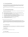
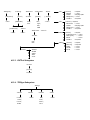
F3: MARK
- (Marker Output) Selects the marker output address of the signal to be available
at the Marker Out connector. The F1:ADDR, F2:LENGTH or F3:ON/OFF can
be selected and the Marker output signal can be available at any desired location
address between the start and stop addresses of the executed waveform. This
marker output feature will allow you to generate a positive TTL level output
signal at the points specified by address and length.
Note: The maximum LENGTH allowed to be set for marker is 4000.
Below is an example to illustrate how marker function works:
Start Address
Markers
Length
Arbitrary waveform
from front panel
channel output
5V
5 V TTL signal
output from rear
Marker Out connector
0
Marker Function Illustration
F4: EDIT
- Refer to section 3.6.4 below for details.
**Changing one of the arbitrary parameters as start and length causes an update of the output waveform to the new
parameters. When exiting the Arbitrary Menu by selecting a different waveform, a message to save the Arbitrary
wave will be displayed. Select YES or NO to save the new waveform. This save functions the same as the SAVE
ARB function.
F3: AMPL/OFST
- Selects the Amplitude or Offset parameter.
In Arbitrary mode, this setting defines the maximum peak-to-peak amplitude of a full-scale
waveform. If the waveform does not use the full scale of data (-8191 to +8191), then its
actual amplitude will be smaller.
- Selects the Offset parameter. Change the offset by using the cursor keys, rotary knob or
numerical keypad. If a certain setting cannot be produced, the waveform generator will
display a “Setting Conflict” message.
F4: INTCLK/EXTCLK - Selects between using the internal clock or external clock.
For Model 4078 only:
For the 4078 with dual channels, channel 1 (CH1) is the MASTER channel. If selected
for external clock (EXTCLK), the same clock will also be applied to channel 2 (CH2) if
EXTCLK is also selected in CH2. (Note: There is only one BNC connector for external clock
input, which is common to both channels)
3.6.4 Arbitrary EDIT Menu
Enters data for creating arbitrary waveforms. You can enter data one point at a time, as a value at an address, draw a
line from one point (a value at an address) to another point, create a predefined waveform, or combine these to
create complex waveforms. The valid data values range is -8191 to 8191. The valid waveform memory addresses
range from 1 to 400,000.
The data value governs the output amplitude of that point of the waveform, scaled to the instrument output
amplitude. Therefore, a value of 8191 corresponds to positive peak amplitude, 0 corresponds to the waveform offset,
and -8191 corresponds to the negative peak amplitude.
Edit Menu
F1: POINT
- This menu allows point by point waveform editing. When selected, the following menu is
displayed:
Point Menu
F1: ADRS - Select the current address in the arbitrary waveform memory.
F2: DATA - Selects the data point value at the current address. You can change the point
value from -8191 to 8191.
F4: PREV - Goes back to previous menu (Edit menu).
F2: LINE
- This menu allows a line drawing between two selected points.
Displays the following menu:
Line Menu
F1: FROM - Selects the starting point address.
F2: TO
- Selects the ending point address.
F4: EXEC - Displays the Confirmation menu, F1:NO and F3:YES
Confirmation Menu
F3: PREDEF
- (Predefined Waveforms) Selects one of the predefined waveforms: Sine, Triangle, Square
and Noise. Displays the Predefined waveforms menu:
Predefine Menu
F1: TYPE - Selects the waveform Sine, Triangle, Square, Noise, Ramp up, Ramp down,
exponential, Sin(x)/x, and Gaussian distribution. If Noise function is selected, a submenu is
displayed to allow adding the noise to an available waveform or to generate it as a new noise
waveform.
F2: FROM DATA
- Selects the starting point of the generated waveform and data value.
F3: LENG/SCALE - Selects the length of the predefined waveform (number of points for a full
wave). The length value must be a number that is divisible by 4 or by 2
in some instances. If not, a pop up message will say “Must divide by 4” or
“Must divide by 2” and entered values will change back to its original.
Different waveforms have different limitations on the length. Refer to
Table 3-1 below. If scale is too high, a message will display “Scale too
high.”
Table 3-1: Waveform Length Limits for Predefined Waveforms
Wave
Sine
Triangle
Square
Noise
Minimum Length
16
16
2
16
Divisible by
4
4
2
1
F3: SCALE - Selects the scale factor of the waveform. 100% means that the waveform
spans the full scale of -8191 to 8191. Scale factors are limited by the point data
value of the starting point and automatically calculated by the unit.
F4: EXEC - Prompts you to confirm whether to execute the selected predefined waveform.
Press NO to abort executing the predefined waveform; press YES to execute the predefined
waveform. On the NOISE function a menu of ADD and NEW is prompt to select a new noise
waveform or to add noise to the existing waveform.
F4: MORE
- Displays the following Menu:
Arbitrary Option Display
F1: COPY - Displays the Copy menu (see the Copy Function later in this section).
F2: CLEAR - Displays the Clear menu (see the Clear Function later in this section).
F3: PROT - Displays the Protect menu (see the Protect Function later in this section).
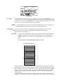
F4: SHOW WAVE - Display the Arbitrary waveform in full screen mode on LCD display. This
is only an approximated display for quick viewing. It does not represent the
exact waveform being generated. To return back to the MENU selection,
press any button.
Full Display Example
Copy Function. Copies an area of waveform memory to another area of waveform memory.
F1: FROM - Selects the address of the first point to copy.
F2: LENG - Selects the length (number of points) of the waveform to copy.
F3: TO
- Selects the destination address where the first point is copied.
F4: EXEC - Prompts you to confirm whether to copy. Press NO to abort copying, YES to copy.
Clear Function. Clears (sets the data values to zero) either a section of or all of waveform memory.
F1: FROM - Selects the address of the first point to clear.
F2: TO
- Selects the address of the last point to clear.
F3: ALL
- Clears the whole waveform memory. Equivalent to selecting from 1 to 400,000.
F4: EXEC - Prompts you to confirm whether to clear. Press NO to abort clearing, YES to clear.
Protect Function. Protects (makes read-only) a section of waveform memory.
F1: FROM - Selects the address of the first point to protect.
F2: TO
- Selects the address of the last point to protect.
F3: ALL
- Protects the whole waveform memory. Equivalent to selecting from 1 to 400,000.
Note: You can protect only one segment of waveform memory at a time.
F4: ON/OFF - Selects the unprotect mode and resets memory protection so that the whole waveform
memory can be written into.
3.6.5 PULSE Menu
Pulse Menu
F2: PULSE
- Selects the Pulse parameters entry.
And then:
F1: FREQ/PERIOD - Selects the parameter definition of the Pulse repetition period.
F2: WIDTH
- Selects the Width of the generated pulse.
F3: EQUAL EDGE - Selects equal Rise (Leading edge) and Fall (Trailing edge) times of the pulse.
F4: LEAD-TRAIL
3.6.6 UTILITY Key
- Selects different Rise and Fall times of the Pulse.
Utility Menu
F1: GPIB
- (optional) Selects the GPIB remote mode of operation. After selection the GPIB address can be
set to any value from 1 to 31 using the rotary knob. The value is kept in a nonvolatile memory and
used at power-on. The factory default address is 9. Setting the address to 31 puts the device in the
off-bus state (it will not respond to messages on the GPIB bus).
F1:RS232
- Selects the RS232 remote control mode. After selection, the baud rate can be selected as
2400, 9600, and 19200. The RS-232 uses 8 bit data, 1 stop bit and no parity.
F2: RECALL - Recalls a previously stored front-panel setup from the selected buffer. Change the buffer
number by using the rotary input knob. Valid storage buffer numbers are from 0 to 49.
Buffer 0 is the factory default setup.
F2: STORE
- Stores the current front-panel setup to the specified storage buffer. Change the buffer
number by using the numeric keypad or the rotary input knob. Valid storage buffer
numbers range from 1 to 49. Below is a list of parameters that can be stored in each
buffer.
Note: Location 50 is for last working setup before power down.
List of Stored Parameters
Stored Parameters
FREQUENCY
RATE(ARB)
AMPLITUDE
FUNCTION
OFFSET
REPETITION
MODE
N-BURST
START ADRS
WAVELENGTH
TRIG SOURCE
*OUTPUT
SWEEP
MODULATION
*For power-on setting, channel output status is not saved and cannot be recalled. For example, if
channel output is ON when storing into memory, it cannot be recalled when that memory is set for
power-on setting. In which case, at power on status of the channel output will always be disabled.
This is for safety reasons because in some cases, if device connected to the generator is sensitive
to signal level, accidentally powering the instrument ON with the output on may damage the
device right away.
**The RECALL and STORE function can be used as a tool to store and locate many arbitrary
waveforms. Because the 4075 and 4078 are designed with one large memory bank (up to 400,000
points of storage), users can have the freedom to store as many waveforms of different lengths as
they desired in a dynamic fashion (with the limit of total points not to exceed memory capacity).
Then, by using STORE and RECALL functions to save the starting address and lengths of each
created arbitrary waveforms, users can quickly locate (in the memory) and output each of the
different waves. These functions can behave like reference points, so users can actually save up to
49 different waveform reference points in the memory.
See example illustration below to see how it works:
Waveform 1
Point
Waveform 2
B pts.
A pts.
Waveform 3
C pts.
Waveform 4
D pts.
1
Point
400,000
A pts. + B pts. + C pts. + D pts. ≤ 400,000 pts.
Stored Buffer number
1
2
3
4
Data points of different waveforms
(Start address + length)
A pts.
B pts.
C pts.
D pts.
From the above illustration, all the points of Waveform 1 can be stored and recalled using buffer #1.
Likewise, Waveform 2 can be stored/recalled by buffer #2. Waveform 3 by buffer #3. Waveform 4 by buffer
#4.
F3: POWER
- (Power-on default) Selects the power-on default setting. Select a value using the numeric keypad
or the rotary input knob. The selection is effective after a 10 s time-out period. Select zero (0) to
have the waveform generator power on with the factory default settings. Select 50 to have the
waveform generator power-on with the settings it had at the last power-off. Select any other value
in the range from 1 to 49 to have the waveform generator power-on with the settings that you have
saved with F2:STORE(see above) in the range of 1 to 49.
Note: Channel output status can be stored and recalled in memory, but cannot be
recalled for power-on setting. Meaning, at any given time, at power on the channel
output status will always be OFF regardless of what memory block power-on setting is
set to recall at power up. This is a safety feature because if user accidentally turns on
with the outputs on, sometimes it can easily damage a connected device that is sensitive
to signal levels connected to it.
3.6.7 SWEEP Key
Selects the Sweep Mode and allows the entering of sweep parameters as Sweep Start, Sweep Stop and Sweep
Rate.
To select the sweep mode, press SWEEP, then press the function key that corresponds to the desired Sweep menu
option, as shown:
Sweep Menu
F1: ON/OFF
- Operates the sweep function, selecting between Sweep On or Off.
F2: START/STOP
- Defines the Sweep Start and Stop frequencies.
F3: RATE
- Defines the Sweep Rate.
F4: LIN/LOG
- Selects the Sweep Shape, LIN or LOG.
Log Sweep Menu
3.6.7.1 How to Setup Sweep in Different Modes
By default, turning ON the sweep function will automatically set to a continuous (CONT) sweep. In
order to change to other modes of sweep, do the following:
1.
2.
3.
Set sweep to ON FIRST by pressing F1.
Then, press the MODE button on front panel.
Select between triggered (TRIG), burst (BURST) or gated (GATE) mode.
Note: If this is done before turning on sweep, sweep ON selection will automatically reset to
default (which sweeps in continuous mode).
3.6.8 MODULATION Key
Selects the Modulation mode AM, FM or FSK.
To select the output mode, press MODUL key, then press the function key that corresponds to the desired
menu option, as shown:
Modulation Menu
F1: AM
If the AM is selected, the following menu is available:
AM Menu
F1: ON/OFF
- Selects the Modulation ON or OFF operating mode.
F2: % /SHAPE
- Defines the modulation depth (from 0 to 100%) and the modulation shape between
SINE, TRIANGLE or SQUARE .
F3: MOD-FREQ
- Selects the modulation frequency, from 0.1 Hz to 20.00 KHz.
F4: EXT/INT
- Selects and enables the external modulation by an external signal applied to the
Modulation In connector.
F2: FM
If the FM is selected, the following menu is available:
FM Menu
F1: ON/OFF
- Selects the Modulation ON or OFF operating mode.
F2: DEV/ SHAPE
- Defines the FM deviation frequency or the modulation shape, between SINE,
TRIANGLE or SQUARE.
F3: MOD-FREQ
- Selects the modulation frequency, from 0.1 Hz to 20.00 KHz.
F4: EXT/INT
- Selects and enables the external modulation by an external signal applied to the
Modulation In connector.
F3: FSK
If the FSK is selected, the following menu is available:
FSK Menu
F1: ON/OFF
- Selects the FSK ON or OFF operating mode.
F2: F-HI/F-LO - Defines the High and Low frequency of the FSK.
F3: RATE
- Selects the rate of alternation between the low and high frequencies.
F5: EXT/INT
- Selects and enables the external FSK when the unit frequency is alternating
between the low and high frequencies by an external signal applied to the Trig
In connector.
3.7 ON Key
Use these key to control the main output signal. When the output is active, an internal LED will illuminate the button.
3.8 Cursor Movement Keys
Use these keys to move the cursor (when visible) either left or right. They are used in conjunction with the rotary input
knob to set the step size of the rotary input knob.
3.9 Rotary Input Knob
Use this knob to increase and decrease numeric values or to scroll through a list. The cursor indicates the low-order
position of the displayed value which changes when you rotate the knob (for straight numeric entries only). For other
types of data, the whole value changes when you rotate the knob.
3.10 Power-On Settings
At power-on, the waveform generator performs a diagnostic self-test procedure to check itself for errors. If it finds an
error, an error code and text will appear in the display window. Other error codes appear when you enter an invalid
front-panel setting. For more information on error codes, see the Error Indication section 3.12.
When the waveform generator finishes the diagnostic self-test routine, it enters the local state (LOGS) and assumes
power-on default settings. Table 3-2 lists the factory default settings. You can program the waveform generator for any
settings you want at power on, as described earlier in section 3.6.6.
Note: OUTPUT status saved into memory cannot be recalled for power-on setting. This is a safety feature to prevent
sensitive devices connected to the generator from being damaged if user accidentally turns on the unit.
Table 3-2
Power-on Default Settings
Key Functions
FREQUENCY
RATE(ARB)
AMPLITUDE
FUNCTION
OFFSET
REPETITION
MODE
N-BURST
START ADRS
WAVELENGTH
TRIG SOURCE
OUTPUT
SWEEP
MODULATION
Values
1.00000000 KHz
1 µs
5.00 V
SINE
0.00 V
10 ms
CONT
2
1
1000
EXT
OFF
OFF
OFF
Comments
Wave frequency
Sample time per point
Peak to peak output amplitude
Output waveform
Zero offset
Internal trigger rate
Waveform mode
Waves per burst
Start memory address
Number of points per waveform
External trigger source
Output disabled
Sweep execution
Modulation execution
3.11 Memory
The waveform generator uses a non-volatile FLASH memory for storing arbitrary waveform data and front panel
settings. Up to 400,000 points Arbitrary waveform and 50 front panel settings are stored. These front panel settings
can be used to store starting address and lengths of many different waveforms stored in memory as reference points for
quick recall.
Because it is impossible to guarantee 100% of the time against loss of stored data, you should maintain a record of the
data stored in memory so that you can manually restore such data, if necessary.
3.12 Displaying Errors
At power-on, the waveform generator performs a diagnostic routine to check itself for problems. If the diagnostic
routine finds an error, an error message is displayed. The waveform generator also displays error messages when frontpanel settings are either invalid or may produce unexpected results.
Error messages for Model 4075and 4078
Message Text
Out of range
Cause
Attempt to set variable out of instrument limits.
Setting conflict
Trig rate short
Empty location
SCALE too high
Protected RAM
Save RAM
Must divide by 4
Must divide by 2
Can't have this parameter set with some other.
Internal trigger rate too short for wave/burst.
Attempt to restore non existent setting.
Attempt to set scale too high for current dot value
Attempt to write to protected RAM range.
New firmware installed.
Predefined wave length must be divisible by 4.
Predefined wave length must be divisible by 2.
3.13 Using Model 4075 and 4078
This section explains how to generate various waveforms and modify the output waveforms.
3.13.1 Selecting a Standard Waveform
You can select several standard waveforms as: sine, triangle and square. Creating a standard waveform requires
selecting the waveform type, parameters, modes, etc., and their settings that define the waveform.
Generating a standard waveform requires the following:
* Selecting the waveform by pushing any of the waveform buttons (Sine, Ramp, Square, Pulse, or Arb)
* Setting the output frequency by using the rotary input knob or numeric keypad to enter the desired frequency.
* Setting the output amplitude and offset by selecting the option in the function menu and using the rotary input
knob or numeric keyboard to enter the desired amplitude and/or offset.
3.13.2 Setting the Output Mode
To set the output mode:
1. Press MODE to display the Mode menu on the display window.
2. Press the function key (Fl to F4) that corresponds to the desired mode. Choose from Continuous, Trigger, Burst,
and Gate mode. You can also adjust the Phase in the same menu.
3.13.3 Setting the Output
To set the output channel, press the Output ON key. An internal LED is illuminated to indicate that the Output is
ON.
3.14 Examples
3.14.1 Creating an Arbitrary Waveform
You can create an arbitrary waveform using the following methods:
* Enter individual data points
*
*
*
*
*
Draw lines between data points
Create a predefined waveform
Export waveform from software
Create data points using SCPI commands
Combine any of these methods
The waveform’s frequency and amplitude are influenced by the number of data points and their value in the waveform.
For further information on how the number of data points influence the frequency and amplitude of a waveform in
execution memory, see Setting the Frequency portion (Section 3.14.3) and Setting the Amplitude portion (Section
3.14.4), respectively.
3.14.2 Entering Individual Data Points
The most basic way to program an arbitrary waveform is to enter data points for the waveform, one data point at a
time. While this can become tedious, the auto-increment function helps this process.
To enter individual data points into waveform memory, follow these steps:
1.
Press ARB main key to display the selection menu.
2.
Press F2: ARB to display the arbitrary menu.
3.
Press F4:EDIT to display the Edit menu.
4.
Press F1:POINT, to select the point by point programming mode.
5.
Press F1:ADRS
6.
Use the rotary knob or the numerical keypad to enter the address.
7.
Press F2:DATA.
8.
Use the rotary knob or the numerical keypad to enter the value for the data point. Valid entries range
from –8191 to 8191.
9. Repeat steps 5 through 8 for additional points until you finish creating your arbitrary waveform.
Note: Each time you press ENTER to complete a data point entry in numerical mode, the auto-increment
address advances the "A= value" by one.
3.14.3 Setting the Arbitrary Frequency
The arbitrary waveform frequency is a function of the number of data points used to run the waveform (the length
parameter in the ARB menu) and the waveform execution point rate. The waveform execution point rate is the
execution time between each point in the waveform. The total time taken to run one period of the waveform is
given by:
𝑇𝑜𝑡𝑎𝑙 𝑡𝑖𝑚𝑒 = # 𝑜𝑓 𝑝𝑜𝑖𝑛𝑡𝑠 ∙ 𝑟𝑎𝑡𝑒
Because the output frequency is a function of the rate and the number of points being executed, the output frequency is
calculated as:
𝑓𝑟𝑒𝑞𝑢𝑒𝑛𝑐𝑦 =
1
# 𝑜𝑓 𝑝𝑜𝑖𝑛𝑡𝑠 ∙ 𝑟𝑎𝑡𝑒
For example, to set the output frequency to 1000 Hz, given the number of data points used for the waveform output is
1000, the rate is calculated as:
𝑟𝑎𝑡𝑒 =
1
= 1 𝜇𝑠
1000 𝑝𝑡𝑠 ∙ 1000 𝐻𝑧
EXAMPLE: Setting the Output Frequency
To set the output frequency of a 1000 point waveform in execution memory to 1000 Hz, set the rate to 1 µs:
ACTION
KEYSTROKES
Step 1. Set the output rate to 1 µs (equivalent to
1000 Hz output frequency)
PARAMETER
F1 :RATE
1
KHz/us
3.14.4 Setting the Amplitude
The following equation represents the relative output amplitude voltage relationship between the front-panel amplitude
peak-to-peak setting and the data point values in waveform memory:
𝑜𝑢𝑡𝑝𝑢𝑡 𝑣𝑜𝑙𝑡𝑎𝑔𝑒 =
𝐴𝑚𝑝𝑙𝑖𝑡𝑢𝑑𝑒 𝑝 − 𝑝 𝑠𝑒𝑡𝑡𝑖𝑛𝑔 ∙ 𝑑𝑎𝑡𝑎 𝑝𝑜𝑖𝑛𝑡 𝑣𝑎𝑙𝑢𝑒
+ 𝑜𝑓𝑓𝑠𝑒𝑡
16382
Where 16382 is the total data point value range in waveform memory.
Table 3-4: Relative Amplitude for Waveform Output (Examples)
Front Panel
Amplitude Setting
5 V peak-to-peak
5 V peak-to-peak
10 V peak-to-peak
Data Point Value
8191
0
-8191
Relative Output
Amplitude Voltage
2.5 V positive peak
0 V (offset voltage)
5 V positive peak
3.14.5 Executing an Arbitrary Waveform
To load a waveform into execution memory, specify its starting address and length in the ARB menu.
1.
2.
3.
Select the channel to ON.
Press the ARB key and select the F2:ARB function.
Press F1:START to set the address. Valid entries range from 1 to 399,999.
Note: The starting address always has to be an odd number. If an even number is entered, it will automatically
decrement one value to an odd number. For example, if you set start address to 2000 and press ENTER, it will
display 1999.
4.
5.
Press F2:LENGTH to set the length of the waveform.
Use the rotary input knob or the numerical keypad to enter the waveform length. Valid entries range from 2 to
400,000.
Note: The length value must always be an even number. If you input an odd number length, a message will pop
up and say “Even wave length” and then decrement one value to an even number. For example, if you entered
1001 as the length, the message will pop up for one second and change the value automatically to 1000.
3.14.6 Using Voltage Offset
Through the offset parameter you can add a positive or negative DC level to the output waveform.
To set voltage offset:
1. Press Waveform to display the menu.
2. Press F3 :OFST to display the offset setting.
3. Use the rotary input knob or the numerical keys to set the voltage offset.
To turn the voltage offset OFF, repeat the steps above, but set the offset voltage level to 0.
3.14.7 Storing and Recalling a Waveform Generator Setup
You can store up to 49 front-panel setups in a part of non-volatile Flash known as the settings storage memory. When
you recall a stored setup, the front-panel settings change to match the settings in the stored setup. These stored and
recalled settings include the starting address and length of the arbitrary memory that is loaded in the execution
memory.
Storing Setups
To store the front-panel setup:
1. Press UTILITY to display the menu.
2. Press F2:STORE to select the Store mode.
3. Use the rotary input knob to select a buffer number. Valid buffer numbers range from 1 to 49. Buffer 0 is a readonly buffer that contains the power-on settings listed in Table 3-2.
Note: The waveform generator does not warn you when you store a setup into a settings buffer that is already
occupied.
Recalling Setups. To recall stored front-panel setup:
1. Press UTILITY to display the menu.
2. Press F2:RECALL to select the Recall mode.
3. Use the rotary input knob to select a buffer number. Valid buffers numbers range from 0 to 49.
Buffer 0 is a read-only buffer that contains the power-on settings listed in Table 3-2.
Section 4
Programming
4.1 Overview
4.1.1 GPIB
This section provides detailed information on programming the 4075 and 4078 via the IEEE 488 bus (referred to
from now as the GPIB - General Purpose Interface Bus). The 4075 and 4078 are programmable over the IEEE 488.1
bus, and its message protocol is compatible with IEEE 488.2. The device command set is compatible with the SCPI
1992.0 standard.
The command syntax as defined by the IEEE 488.2 and SCPI standards is briefly explained in the following
sections. Users who have experience programming GPIB instruments may skip these paragraphs, and go directly to
where the individual command syntax is given in sections 4.12 and 4.13. Considering the relative newness of these
standards, it is recommended to all users to read the explanations given here. Users wishing to gain further insight
should consult the standards.
4.1.2 RS-232-C
The RS-232-C standard is not very specific about many of the handshaking signals and it is therefore usually
necessary to refer to the manuals for both of the devices being connected to determine the exact pin out, signal
definition, and signal direction for the devices. Refer to section 2.9 .
The serial interface implements the same SCPI command set as the GPIB interface. This includes commands stated
in sections 4.12 and 4.13. Refer to these sections for syntax details. The instrument is programmed by sending
ASCII coded characters to the instrument.
When the instrument is in the remote mode, remote command input has priority over any front panel control.
Therefore, as long as the serial interface is continuously supplied with data, the keyboard will appear to be
inoperative to the user.
Note: In remote mode, any command sent or receive via RS232 will change the display screen with the
following:
User can return to local control with the press of any front panel keys, but it is extremely important to note that
this should be done ONLY when nothing is being sent or transferred between the instrument and the connected
PC. Any interruptions during transfer may delay the communication process. For large waveforms
transmission, be it sending or receiving, please allow at least 15 seconds before pressing any front panel keys to
return to local mode. The instrument needs the additional time to completely generate or send the waveform.
The instrument accepts a carriage return (CR) as an end of string (EOS) terminator and sends both a CR and LF as
the EOS terminator.
4.2 Device State
The device may be in one of the four possible states described below. The transition between states is defined by
IEEE 488.1.
4.2.1 Local State (LOCS)
In the LOCS the device may be operated from the front panel only. Its settings may be queried over the GPIB, but
not changed. Commands that do not affect the signal being output by the instrument are accepted.
4.2.2 Local With Lockout State (LWLS)
In the LWLS the device may be operated from the front panel only. Its settings may be queried over the GPIB, but
not changed. Commands that do not affect the signal being output by the instrument are accepted. The difference
between the LOCS and the LWLS is that from the LWLS the device may enter the Remote With Lockout State.
4.2.3 Remote State (REMS)
In the REMS the device may be operated from the GPIB. Actuating any front panel key will cause the device state
to revert to the LOCS.
4.2.4 Remote With Lockout State (RWLS)
In the RWLS the device is operable only from the GPIB. Front panel operation may be returned by either sending an
appropriate IEEE 488.1 command, or by cycling the device power.
4.3 Interface Function Subsets
The following interface function subsets are implemented in the MODEL 4075 and 4078:
SH1, AH1, T6, L4, SR1, RL1, PP0, DC1, DT1, E2, C0
4.4 Device Address
The GPIB address of the device may be set to any value from 0 to 31. The address may be changed from the front
panel, using the numeric keypad or the rotary encoder, or via the GPIB itself using the command:
:SYSTem:COMMunicate:GPIB:ADDRess
Setting the device to address 31 puts it in the 'off-bus' state. In this state it will not respond to messages on the GPIB.
If the device is in the REMS when set to address 31, an internal 'return-to-local' command will be given, setting the
device to the LOCS. If the device is in the RWLS, the 'return-to-local' command is ignored, and the device remains
in the RWLS. The only way to then re-establish communication with the device over the GPIB is to cycle the power,
and to then change the address to that required from the front panel.
4.5 Message Exchange Protocol
The device decodes messages using the Message Exchange Protocol (MEP) defined in IEEE 488.2. The following
functions implemented in the MEP must be considered:
4.5.1 The Input Buffer
The device has a 256-byte long cyclic input buffer. Decoding of remote messages begins as soon as the input buffer
is not empty, that is, as soon as the controller has sent at least one byte to the device. Should the input buffer be
filled up by the controller faster than the device can remove the bytes and decode them, the bus handshake is not
completed until room has been made for more bytes in the buffer. This prevents a fast controller from overrunning
the device with data.
If the user has sent part of a Program Message, but not the Program Message Terminator, and he wishes to abort the
message decoding and execution, the Device Clear command may be sent, or front panel operation resumed (in
REMS only).
4.5.2 The Output Queue
The device has a 100-byte long output queue in which it stores response messages for the controller to read. If at the
time a response message is formatted the queue contains previously formatted response messages, such that there are
not enough places in the queue for the new message, the device will put off putting the message in the queue until
there is place for it.
The Status Byte MAV bit, when set, indicates that part or all of a response message is ready to be read.
4.5.3 Response Messages
The device sends a Response Message in response to a valid query. All queries return a single Response Message
Unit. In only one case is the Response Message generated when the response is read (as opposed to when the
response is parsed), and this is when querying Arbitrary Waveform data. All other queries generate the Response
Message when they are parsed.
4.5.4 Coupled Commands
Coupled Commands are either commands whose execution validity depends on the value of other parameters, or
commands whose execution changes the value of another parameter. The execution of commands designated as
being coupled is deferred until all other commands in the same Program Message have been executed. The coupled
commands are then grouped together according to their functionality, and executed as a group. These groups of
coupled commands are defined in the MODEL 4075 and 4078:
a) The commands to set the amplitude, the offset, and to switch the output on. The output being switched on is
included here in order to prevent possible damage to the equipment being driven as a result of the amplitude and
offset not being executed as intended by the user, due to an execution error.
b) The commands to set the function, frequency, the point rate, the wavelength, and the waveform start address. In
ARB function, setting the frequency or the point rate causes the other to change, keeping the wavelength constant (if
it, too, is not specified in the same program message). If the wavelength is specified as well, the frequency or point
rate must change in accordance with the new value. The validity of the start address is a function of the wavelength.
Please refer to the individual commands for more detail.
The maximum frequency is also dependent upon the waveform, so that changing the waveform may render the
current frequency out of range.
c) The commands to set modulation, modulation source and the function are inter-related. FM and FSK are not
available for ARB function. External source of modulation can be active for either FM or AM but not both. FSK and
FM cannot be active at the same time.
d) Sweep start and sweep stop frequencies must be distanced more than the minimum allowed for sweep to function
correctly.
4.6 Block Data (GPIB Only)
Arbitrary waveform values may be sent to the device in one of three formats:
a) ASCII values,
b) Definite form arbitrary data, and
c) Indefinite form arbitrary data.
4.7 Instrument Identification
The *IDN? common query is used to read the instrument's identification string. The string returned is something similar
to the following:
B&K, MODEL 4078,0,V1.03
4.8 Instrument Reset
The *RST common command effects an instrument reset to the factory default power up state.
4.9 Self Test
The *TST common query causes the device to perform a self test. This self test consists of checking the functionality of
the arbitrary waveform memory.
4.10 Command Syntax
4.10.1 General Command Structure
The device commands are generally defined by the SCPI standard, with the exception of those instrument functions
for which SCPI commands do not as yet exist. The Common Commands and Queries are defined by IEEE 488.2.
The command syntax, i.e. how a command is structured, is defined by IEEE 488.2.
A Program Message is defined as a string containing one or more Program Message Units, each of which is an
instrument command or query. Program Message Units are separated from each other by the Program Message Unit
Separator. The Program Message is terminated by the Program Message Terminator.
The Program Message Unit Separator consists of a semicolon (';'), optionally preceded and/or followed by
whitespace characters. A whitespace character is defined as the ASCII characters in the ranges 00H-09H, and 0BH20H. This range includes the ASCII control characters and the space, but excludes the Linefeed character.
The Program Message Terminator consists of optional whitespace characters, followed by one of three options:
a) The Linefeed (LF) character (ASCII 0A);
b) The GPIB EOI bus line being set true on the last byte of the message;
c) LF being sent with EOI true.
The Program Message Unit can be divided into three sections as follows:
a) Program Header
The Program Header represents the operation to be performed, and consists of ASCII character mnemonics. Two
types of Program Headers are used in the 4075 & 4078: Instrument-control headers and Common Command and
Query headers. A Program Header may consist of more than one mnemonic, in which case the mnemonics are
separated from each other by the colon (':'). For instrument control commands, the mnemonics are specified by the
SCPI standard, and indicate the tree structure of the command set. The first mnemonic indicates the subsystem being
controlled. Common Command and Query Program Headers consist of a single mnemonic prefixed by an asterisk
('*').
The mnemonics consist of upper - or lower-case alpha characters. Mnemonics may be written in either the long
form, in which the entire mnemonic is written out, or the short form, in which only a specified portion of the
mnemonic is written out. Some mnemonics have only one form due to their short length. Where a command is
described, the portion appearing in upper case is the short form. Only the short form or the long form may be used.
Example: The command to set the frequency to 1KHz may be written in the following ways:
SOURCE:FREQUENCY 1KHZ
SOUR:FREQ 1KHZ
SOURCE:FREQ 1KHZ
Some mnemonics in a specified Program Header may be optional. This is indicated in the command description by
the mnemonic being enclosed in square brackets ([...]). This means it is not necessary to write the mnemonic into the
Program Header: it is a default condition. The 'SOURCE' mnemonic, for example, is optional. Not specifying it will
cause the device to search for the mnemonics in the Program Header under the Source Subsystem. For example, the
frequency may be set by the commands
FREQ:CW 1KHz
FREQ 1KHz
since the 'CW' mnemonic is also optional.
b) Program Header Separator
The Program Header Separator is used to separate the program header from the program data. It consists of one or
more whitespace characters, denoted as <ws>. Typically, it is a space.
c) Program Data
The Program Data represent the values of the parameters being set, for example, the '1KHZ' in the above
examples. Different forms of program data are accepted, depending on the command. The Program Data types used
in the instrument are:
i) Character program data
This form of data is comprised of a mnemonic made up of lower - or upper-case alpha characters. As with Program
Header mnemonics, some Character Data mnemonics have short and long forms. Only the short or the long form
may be used.
ii) Boolean data
Boolean data indicate that the parameter can take one of two states, ON or OFF. The parameter may be character
type
ON or OFF
or numeric. A numeric value is rounded to an integer. A non-zero result is interpreted as 1 (ON), and a zero result as
0 (OFF).
Queries return the values 0 or 1.
iii) NRf
This is a decimal numeric data type, where
NR1 indicates an integer number,
NR2 indicates a fixed point real number, and
NR3 indicates a floating point real number.
iv) Expression data
An expression is contained in parentheses (...). This data type is used only with the
STATus:QUEue:ENABle command.
v) Numeric value program data
This data type defines numeric values, as well as special cases of Character Data. Numeric values may be
specified in any of Integer, Fixed Point or Floating Point format. All parameters which have associated
units accept a suffix, which may be specified using upper or lower-case characters. When the suffix is not
specified, the numeric value is accepted in the default units, which are Hertz for frequency, Seconds for
time, and Volts for voltage. To set the frequency to 1 KHz we can send one of the following commands:
FREQ 1000
FREQ 1E3
The special forms of character data accepted as numbers are
MAXimum: sets the parameter to its maximum value.
MINimum: sets the parameter to its minimum value.
For example, to set the frequency to its maximum value we can send the command
FREQ MAX
vi) Arbitrary Block Data
The Arbitrary block data type is used to send arbitrary waveform data to the instrument. In this data type,
the waveform points are specified in binary format, and each point consists of two bytes. Two types of
arbitrary block data are defined (by IEEE 488.2):
Definite Form
ִ
The Definite Form has the structure
-#-Byte Count Length - Byte Count - 8-bit byte
The Byte Count Length consists of a single ASCII digit from 1 to 9. It tells the parser how many digits are
in the Byte Count.
The Byte Count is a decimal integer made up of the number of digits specified in the Byte Count Length. It
tells the parser how many 8-bit bytes are being sent.
Indefinite Form
The Indefinite Form has the structure
- # - 0 – 8-bit byte – LF^EOI
Some Program Message Units either require, or can accept, more than one data element. Program data elements are
separated from each other by the Program Data Separator. It is defined as optional whitespace characters followed
by a comma (','), which in turn is followed by optional whitespace characters.
There are two types of Program Message Units: Command Message Units and Query Message Units. A Query
differs from a Command in that the Program Header is terminated with a question mark ('?'). For example, the
frequency might be queried with the following query:
FREQ?
Some Query Message Units accept data, giving the device more specific information about what is being queried. In
many cases the Query Message Unit may optionally be supplied with the MIN or MAX mnemonics as data. This
tells the device to return the minimum or maximum value to which the parameter may currently be set. For example,
FREQ? MAX
will return the maximum value to which the frequency may currently be set.
Not all Program Message units have query forms ( for example, STATUS:PRESET), and some Program Message
Units might have only the query form (for example SYSTEM:VERSION?).
The instrument puts the response to the query into the output queue, from where it may be read by the controller.
The Status Byte MAV bit is set to indicate to the controller that a response is ready to be read.
4.10.2 SCPI Command Structure
SCPI commands are based on a hierarchical structure. This allows the same instrument-control header to be used
several times for different purposes, providing that the mnemonic occurs in a unique position in the hierarchy. Each
level in the hierarchy is defined as a node. Mnemonics in the different levels are separated from each other by a
colon (':'). The first Program Message Unit, or command, in a Program Message is always referenced to the root
node. Subsequent commands are referenced to the same level as the previous command. A Program Message Unit
having a colon as its first character causes the reference to return to the root. This process is defined by IEEE 488.1,
section A.1.1. Consider the following examples:
a) The following command may be used to set the amplitude and the offset of the signal.
SOURCE:VOLTAGE:AMPLITUDE 5V;OFFSET 2V
Note that the offset command is referenced to the command preceding it: the OFFSET mnemonic resides at the
same node as the AMPLITUDE command.
b) This command set the frequency and the amplitude.
SOURCE:FREQUENCY 2KHZ;VOLTAGE:AMPLITUDE 4V
The FREQUENCY and VOLTAGE mnemonics are at the same level.
c) When Program Message Units describe different subsystems, a colon prefix must be used to reset the
command reference to the root. Here the frequency and the output state are set.
SOURCE:FREQUENCY 3KHZ;:OUTPUT:STATE ON
Common Commands may be inserted in the Program Message without affecting the instrument-control
command reference. For example,
SOURCE:VOLTAGE:AMPLITUDE 4V;*ESE 255;OFFSET 2V
FOR MODEL 4078 ONLY:
Exclusively for the model 4078 with multiple channels, the selection of which channel to use is achieved through the
use of a numeric suffix indicating the channel, attached to the root level mnemonic. Four root level mnemonics are
channel-dependent, and these are SOURce, TRIGger, OUTPut and ARBitrary. When the channel is not specified,
channel 1 is assumed by default. Program message units that are referred back to a specific root level mnemonic
operate on the channel specified in that mnemonic.
Examples:
a)
SOUR:FREQ 5KHZ;VOLT:AMPL 3V
Sets the frequency and amplitude of the first channel (default).
b) SOUR2:FREQ 5KHZ;VOLT:AMPL 3V
Sets the frequency and amplitude of channel 2.
c)
ARB2:START 100;LENGTH 50
Sets the start address and length of the waveform being output on channel 2.
4.11 Status Reporting
The instrument is capable of reporting status events and errors to the controller, using the IEEE 488.1 Service
Request function and the IEEE 488.2 Status Reporting structure.
4.11.1 The Status Byte
Status summary information is communicated from the device to the controller using the Status Byte (STB). The
STB is composed of single-bit summary-messages, each summary message summarizing an overlying Status Data
Structure. By examining the content of the STB, the controller gains some information concerning the instrument's
status.
The STB bits are defined as follows:
Bit 0:
Bit 1:
Bit 2:
Bit 3:
Bit 4:
Bit 5:
Bit 6:
Bit 7:
Unused
Unused
Error/event queue summary message (EVQ). This bit is set if the queue is not empty.
Questionable Status summary message.
Message Available (MAV) summary message. This bit is set whenever all or part of a message is available for
the controller to read. The controller may be ready to read the response message before it is available, in which
case it can either wait until this bit is set, or it can start to read. In the second case, the controller timeout must
be set so that the read action will not be aborted before the message has been read.
Event Status Bit (ESB) summary message. This bit is set to indicate that one or more of the enabled standard
events have occurred.
Request Service (RQS). This bit is set when the device is actively requesting service.
Operation Status summary message. No Operation Status events are defined in the instrument, and so this bit is
never set.
The STB is read by the controller during a serial poll. If the RQS bit was set, it is then cleared. The STB may
also be read by the *STB? common query.
4.11.2 Service Request Enabling
Service request enabling allows the user to select which Status Byte summary messages may cause the device to
actively request service. This is achieved using the Service Request Enable Register, which is an 8-bit register
whose bits correspond to those of the STB. The RQS bit in the STB is set when a bit in the STB is set, and its
corresponding bit in the service request enable register is set.
The service request enable register is set using the *SRE common command, and read using the *SRE? common
query.
4.11.3 Standard Event Status Register
The Standard Event Status Register (SESR) is defined by IEEE 488.2. It is implemented in the instrument as a byte,
whose bits have the following definitions:
Bit 0:
Bit 1:
Bit 2:
Bit 3:
Bit 4:
Bit 5:
Bit 6:
Bit 7:
Operation Complete (OPC). This bit is set in response to the *OPC common command being executed.
Request Control (RQC). Not implemented.
Query Error (QYE). This bit is set when either the controller is attempting to read data from the device when
none is available, or when data prepared for the controller to read has been lost.
Device-Specific Error (DDE). This bit is set to indicate that a device operation did not execute due to some
device condition. For example, trying to recall an uninitialized device stored setting.
Execution Error (EXE). This bit is set when the device could not execute a command, due to the command
being outside of its capabilities. For example, a parameter being out of range.
Command Error (CME). This bit is set to indicate an error in the command syntax.
User Request (URQ). This bit is not used.
Power On (PON). This bit is set when the device is powered on.
The SESR is queried using the *ESR? common query.
The SESR is paired with an enable register, the Standard Event Status Enable Register (SESER). This register
enables one or more events in the SESR to be reflected in the Status Byte ESB summary message bit. The bits of the
SESER correspond to those of the SESR. Setting a bit in the SESER enables the corresponding event to set the ESB
bit when it occurs. The SESER is set with the *ESE common command and queried with the *ESE? command
query.
4.11.4 The Error Queue
The error queue is used to store codes of errors detected in the device. It is implemented as a cyclic buffer of length
10. When the error queue is not empty, bit EVQ in the Status Byte is set. The error queue is read with either one of
the following two queries:
:SYSTEM:ERROR?
:STATUS:QUEUE:NEXT?
The first error in the queue is returned, and the queue is advanced.
4.11.5 Error Codes
The negative error codes are defined by SCPI. Positive codes are specific to the instrument.
The error message is returned in the form
<error number>,"<error description>"
A table of error numbers and their descriptions is presented here.
No error reported
0
No error
Command Errors
A command error is in the range -199 to -100, and indicates that a syntax error was detected. This includes the case
of an unrecognized header. The occurrence of a command error causes the CME bit (bit 5) of the Standard Event
Status Register to be set.
-100
-101
-102
-103
-104
-105
-108
-109
-110
-111
-112
-113
-120
-121
-123
-124
-128
-131
-134
-138
-140
-141
-144
-148
-158
-161
-168
-170
-171
Command Error
Invalid character
Syntax error
Invalid separator
Data type error
GET not allowed
Parameter not allowed
More parameters than allowed were received
Missing parameter
Fewer parameters than necessary were received
Command header error
Header separator error
Program mnemonic too long
The mnemonic must contain no more than 12 characters.
Undefined header
Numeric data error
Invalid character in number
Exponent too large
IEEE 488.2 specifies maximum of 32000
Too many digits
IEEE 488.2 specifies maximum of 255 digits in mantissa.
Numeric data not allowed
A different data type was expected
Invalid suffix
Suffix too long
A maximum of 12 characters are allowed in a suffix.
Suffix not allowed
Character data error.
Invalid character data.
Incorrect character data were received.
Character data too long
Character data may contain no more than 12 characters.
Character data not allowed
String data not allowed
Invalid block data
An error was found in the block data
Block data not allowed
Expression error
Only 6 error ranges may be specified.
Invalid expression
An error was found in the expression.
-178
Expression data not allowed
Execution Errors
An execution error indicates that the device could not execute a syntactically correct command, either since the data
were out of the instrument's range, or due to a device condition. The EXE bit (bit 4) of the Standard Event Status
Register is set on occurrence of an execution error.
-200
-201
-211
-220
-221
-222
-223
-224
-258
Execution error
An attempt was made to RECALL the contents of an uninitialized stored setting buffer.
Invalid while in local.
Trigger ignored.
The GET or *TRG common command was ignored due to the device not being in the correct state
to execute the trigger.
Parameter error.
A parameter is in the correct range, but conflicts with other parameters.
Settings conflict.
The parameter is out of range due to the current instrument state.
Data out of range.
Too much data.
The arbitrary waveform memory limit has been exceeded.
Illegal parameter value.
The parameter value must be selected from a finite list of possibilities.
Media protected.
An attempt was made to write to protected arbitrary waveform memory.
Device-Specific Errors
An error specific to the device occurred. The DDE bit (bit 3) of the Standard Event Status Register is set.
-315
-330
-350
Configuration memory lost.
Device memory has been lost.
Self-test failed.
Queue overflow.
Error codes have been lost due to more than 10 errors being reported without being read.
Query Errors
A query error indicates that the output queue control has detected a problem. This could occur if either an attempt
was made to read data from the instrument if none was available, or when data were lost. Data could be lost when a
query causes data to be formatted for the controller to be read, and the controller sends more commands without
reading the data.
-410
-420
-430
-440
Query INTERRUPTED.
Data were sent before the entire response of a previous query was read.
Query UNTERMINATED.
An attempt was made to read a response before the complete program message meant to generate
that response was sent.
Query DEADLOCKED.
The input buffer and output queue are full, and the controller is attempting to send more data. In
this case the output queue and input buffers will be cleared. Parsing will resume after the END
message is detected.
Query UNTERMINATED after indefinite response.
A query was received in the same program message after a query requiring an indefinite response
was formatted. Essentially this means that the *IDN? common query and the :ARB:DATA? query
should not be followed by more query messages in the same program message.
System Events
System events have positive valued codes. They are not defined by SCPI, but are specific to the instrument. Sending
the :STATus:PRESet command will disable these events from being reported.
401
402
Power on
Operation complete
The *OPC command has been executed.
Warnings
The execution of some commands might cause an undesirable instrument state. The commands are executed, but a
warning is issued. Sending the :STATus:PRESet command disables reporting of warnings. The existence of these
conditions causes a bit in the Status Questionable Condition register to be set (refer to section 4.13.5.4).
For Model 4075
500
510
Trigger rate short
Output overload
For Model 4078
500
501
510
511
Trigger rate short on channel 1
Trigger rate short on channel 2
Output overload on channel 1
Output overload on channel 2
"Trigger rate short" means that the period of the waveform is larger than the value of the internal trigger rate. Thus
not every trigger will generate a cycle (or burst) of the waveform.
4.12 Common Commands
The following section describes the common commands according to the IEEE 488.2 specifications. These
commands are applicable for both GPIB and RS-232 interface.
4.12.1 System Data Commands
a) *IDN? - Identification query
The identification query enables unique identification of the device over the GPIB. This query should
always be the last in a program message. It returns a string with four fields:
Manufacturer name
Model name
Serial number (0 if not relevant)
Version number
Command
Type:
Syntax:
Common Query
*IDN?
Response:
B&K, MODEL 4078,0,V1.03
b) *OPT? - Option identification query
The Option Identification Query is used to identify device options over the system interface. This query
should always be the last in a program message.
Command
Type:
Syntax:
Response :
Common Query
*OPT?
No option available.
4.12.2 Internal Operation Commands
a) *RST - Reset command
The Reset command performs a device reset. It causes the device to return to the factory default power up
state.
Type:
Syntax:
Common Command
*RST
b)*TST? - Self-test query
The self-test query causes an internal self-test to be performed. This test consists of checking the integrity
of the arbitrary waveform memory.
Type:
Syntax:
Response:
Common Query
*TST?
ASCII 0 if test passes
ASCII 1 if test fails
4.12.3 Synchronization Commands
a) *OPC - Operation complete command
The operation complete command causes the device to generate the operation complete message in the
Standard Event Status Register, on completion of the selected device operation.
Type:
Syntax:
Examples:
Common Command
*OPC
FREQ 5KHZ;*OPC
The *OPC command (and the *OPC? query described below) find use mainly when commands having
relatively long execution times are executed, for example the programming of long predefined waveforms.
b) *OPC? - Operation complete query
The operation complete query places an ASCII character 1 in the output queue on completion of the
selected device operation.
Type:
Common Query
Syntax:
Response:
Example
*OPC?
ASCII character 1
FREQ 1KHz;*OPC?
c) *WAI - Wait-to-continue command
This command is intended for use with overlapped commands. No commands in the instrument are
overlapped, and so this command has no effect.
Type:
Syntax:
Common Command
*WAI
4.12.4 Status and Event Commands
a) *CLS - Clear status
The clear status command clears the SESR and Error Queue status data structures.
Type:
Syntax:
Common Command
*CLS
b) *ESE - Standard event status enable
This command is used to set the value of the Standard Event Status Enable Register.
Arguments
Type:
NRf
Range:
0 to 255. Non integer arguments are rounded before execution.
Type:
Common Command or Query
Syntax:
*ESE<ws><NRf>
Examples: *ESE 48 (Enables the CME and EXE bits)
*ESE 255 (Enables all standard events)
Query
Syntax:
*ESE?
Response:
<NR1>
c) *ESR? - Standard event status register query
This query is used to read the value of the Standard Event Status Register. Reading the register clears it.
Type:
Syntax:
Response:
Common Query
*ESR?
<NR1>
d) *PSC - Power on status clear command
This command is used to control the automatic power-on clearing of certain status functions.
Arguments
Type:
Boolean
Type:
Common Command or Query
Command
Syntax:
*PSC<ws><Boolean>
Examples: *PSC ON or *PSC 1
*PSC OFF or *PSC 0
Query
Syntax:
*PSC?
Response:
ASCII 0 for OFF
ASCII 1 for ON
When set to ON (1), the Service Request Enable Register and the Standard Event Status Enable Register
are cleared on power-on.
e) *SRE - Service request enable command
This command sets the Service Request Enable Register bits.
Arguments
Type:
NRf
Range:
0 to 255. Non integer arguments are rounded before execution.
The value of bit 6 is ignored, and is set always to zero.
Type:
Command
Syntax:
Examples:
Query
Syntax:
Response:
Common Command or Query
*SRE<ws><NRf>
*SRE 48 (Enables reporting of ESB and MAV events)
*SRE?
<NR1>
f) *STB? - Status byte query
This query is used to read the value of the Status Byte.
Type:
Syntax:
Response:
Common Query
*STB?
<NR1>
The value of the Status Byte read with the *STB? query may differ from that read with the Serial Poll. Bit 6
of the STB will be set as long as a reason for requesting service exists, while bit 6 of the STB as read by the
Serial Poll is cleared by the Serial Poll.
4.12.5 Device Trigger Commands
a) *TRG - Trigger command
This command is analogous to the IEEE 488.1 Group Execute Trigger interface message, and has the same
effect. It is used to trigger the device to output a wave, and is accepted only when the trigger mode is set to
Trigger, Gate or Burst, and the trigger source is set to BUS.
Type:
Syntax:
Common Command
*TRG
4.12.6 Stored Settings Commands
a) *RCL - Recall instrument state
This command is used to restore the state of the device to that stored in the specified memory location.
Arguments
Type
<NRf>
Range
0 to 49. Non integer values are rounded before execution
Type:
Syntax:
Example:
Common Command
*RCL<ws><NRf>
*RCL 0 (Recall default state)
*RCL 49
Stored setting location 49 stores the last instrument setting before power down.
b) *SAV - Save instrument state
This command is used to store the current instrument state in the specified memory location.
Arguments
Type:
<NRf>
Range:
1 to 49. Non integer values are rounded before execution
Type:
Common Command
Syntax:
*SAV<ws><NRf>
Example:
*SAV 25
Stored setting location 0 stores the factory defaults, and is a read-only location. Location 50 stores a copy
of the current instrument setting, and it, too, is read-only.
4.13 Instrument Control Commands
Instrument control commands are grouped into logical subsystems according to the SCPI instrument model. They
can be used when interfacing with GPIB or RS-232. The commands are comprised of mnemonics indicating the
subsystem to which the command belongs, and the hierarchy within that subsystem. When the command is to be
referred to the Root node, it should be prefixed with a colon (:). Mnemonics appearing in square brackets [...] are
optional. The '|' character is used to denote a choice of specifications. The '<ws>' is used to denote a white space
character.
4.13.1 SOURce Subsystem
The Source Subsystem controls the frequency, voltage, amplitude modulation and clock source. The command
structure is as follows:
:SOURce
:FREQuency
[:CW|:FIXed] <numeric value>
:PRATe <numeric value>
:FUNCtion
[:SHAPe] SINusoid|SQUare|TRIangle||ARBitrary||PULSe
: DCYCle ] <numeric value>
:VOLTage
[:AC]
[:LEVel]
[:IMMediate]
[:AMPLitude] <numeric value>
:OFFSet <numeric value>
:REFerence
[:SOURCE] INTernal |EXTernal
:AM
[:STATe] <Boolean>
:DEPTh <numeric value>
:SHAPe SINusoid|SQUare|TRIangle
:FREQuency <numeric value>
:SOURce INTernal |EXTernal
:FM
[:STATe] <Boolean>
:DEViation <numeric value>
:SHAPe SINusoid|SQUare|TRIangle
:FREQuency <numeric value>
:SOURce INTernal |EXTernal
:FSK
[:STATe] <Boolean>
:LOWFrequency <numeric value>
:HIFrequency <numeric value>
:RATE <numeric value>
:SOURce INTernal |EXTernal
:SWEep
:STATe <Boolean>
:SPACing <LIN|LOG>
:TIME <numeric value>
:STARt <numeric value>
:STOP <numeric value>
:PHAse
[:ADjust] <numeric value >
:PULSe
:PERiod <numeric value >
:WIDth <numeric value >
:EDGe <numeric value >
:RISe <numeric value >
:FALl <numeric value >
Note: For model 4078, nothing changes in the commands above to control channel 1. But for channel 2, change
:SOURce to :SOUR2. For example, to change channel 2 to SINE function, send the command:
SOUR2:FUNC SIN.
4.13.1.1 Frequency
:SOURce:FREQuency <frequency>
The frequency command controls the frequency of the output waveform.
Arguments
Type:
Numeric.
Units:
MHz, KHz, Hz (default)
Range:
Dependent on the Point Rate and Wavelength.
Fmax = 1/(10nS * Wavelength)
Fmin = 1/(100S * Wavelength)
Rounding: The value is rounded to 4 digits.
Command Type: Setting or Query
Setting
Syntax:
[:SOURce]:FREQuency[:CW]<ws><frequency>[units]
[:SOURce]:FREQuency<ws>MINimum|MAXimum
Examples: :FREQ 5KHZ
:FREQ 5E3
:FREQ MAXIMUM
:FREQ MIN
Query
Syntax:
Examples:
Response:
[:SOURce]:FREQuency[:CW]?[<ws>MAXimum|MINimum]
:FREQ?
:FREQ? MAX
NR3
Considerations:
1) The MIN | MAX arguments should be used only in a Program Message that does NOT contain Program
Message Units specifying Arbitrary Point Rate or Wavelength, since the MAXimum or MINimum value is
calculated at the time the command is parsed.
2) The MIN and MAX arguments refer to currently settable minimum or maximum.
3) FIXed is alias for CW.
4.13.1.2 Amplitude
:SOURce:VOLTage[:AMPLitude] <p-p amplitude>
The amplitude command is used to set the peak-to-peak amplitude of the output waveform. Note that the amplitude
and the offset are limited by the relation
Peak Amplitude + |Offset| ≤ 5V
Arguments
Type:
Units:
Range:
Rounding:
Command Type:
Setting
Syntax:
Examples:
Query
Syntax:
Examples:
Response:
Considerations:
Numeric
V, mV
10mV to 10V
1mV from 10mV to 999mV. 10mV from 1V to 10V.
Setting or Query
[:SOURce]:VOLTage:AMPLitude<ws><amplitude>[units]
[:SOURce]:VOLTage:AMPLitude<ws>MINimum|MAXimum
:VOLT:AMPL 2.5
:VOLT:AMPL 2.5V
:VOLT:AMPL MAX
[:SOURce]:VOLTage:AMPLitude?
[<ws>MINimum|MAXimum]
:VOLT:AMPL?
:VOLT:AMPL? MAX
NR2
1) The MAXimum amplitude is dependent on the offset.
2) The MAX and MIN arguments should not be used in a program message containing an OFFSet
command, since these values are evaluated during parsing, based on the current value of the offset.
4.13.1.3 Offset
:SOURce:VOLTage:OFFSet <offset>
The offset command is used to set the DC offset of the output waveform. Note that the amplitude and the offset are
limited by the relation
Peak Amplitude + |Offset| ≤ 5V
Arguments
Type:
Units:
Range:
Rounding:
Command Type:
Setting
Syntax:
Examples:
Query
Syntax:
Examples:
Response:
Considerations:
Numeric
V, mV
10mV to 4.99V
to 10mV
Setting or Query
[:SOURce]:VOLTage:OFFSet<ws><offset>[units]
[:SOURce]:VOLTage:OFFSet<ws>MINimum|MAXimum
:VOLT:OFFS 2.5
:VOLT:OFFS 2.5V
:VOLT:OFFS MAX
[:SOURce]:VOLTage:OFFSet?[<ws>MINimum|MAXimum]
:VOLT:OFFS?
:VOLT:OFFS? MAX
NR2
1) The MAXimum offset is dependent on the amplitude.
2) The MAX and MIN arguments should not be used in a program message containing an AMPLitude
command, since these values are evaluated during parsing, based on the current value of the amplitude.
4.13.1.4 Clock Reference Source
:SOURce:REFerence:SOURce <clock source>
This command is used to select the source of the arbitrary waveform clock. This clock sets the arbitrary waveform
point rate.
Arguments
Type:
Options:
Command Type:
Setting
Syntax:
Examples:
Query
Syntax:
Response:
Character
INTernal, EXTernal
Setting or Query
[:SOURce]: REFerence
:SOURce<ws><option>
:REF:SOUR INT
:REF:SOUR EXT
[:SOURce]: REFerence :SOURce?
INT|EXT
4.13.1.5 Function
:SOURce:FUNCtion [:SHAPe]
The function command is used to set the type of waveform to be generated by the instrument.
Command Type: Setting or Query
Setting
Syntax:
[:SOURce]:FUNCtion[:SHAPe]<WS><OPTION>
Examples: : FUNC SIN
:FUNC ARB
Query
Syntax:
[:SOURce]:FUNCtion[:SHAPe]?
Examples:
:FUNC?
Response:
SIN|TRI|SQU|ARB|PUL
Considerations:
The following functions are available:
Sinusoid, Square, TRIangle, ARBitrary, PULse
4.13.1.6 Point Rate
:SOURce:PRATe <point rate>
This command is used to set the point rate. It is coupled with the frequency of the waveform by the relation
Frequency = 1/(Point Rate * Wavelength)
Thus changing the point rate will result in a change in frequency.
Arguments
Type:
Numeric
Units:
S, mS, uS, nS
Range:
10nS to 100S
Rounding:
To 4 digits
Command Type: Setting or Query
Setting
Syntax:
:SOURce:PRATe<ws><point rate>[units]
:SOURce:PRATe<ws>MINimum|MAXimum
Examples:
:ARB:PRAT 500NS
Query
Syntax:
:ARBitrary:PRATe?[<ws>MINimum|MAXimum]
Response:
NR3
4.13.1.7 AM modulation
The following sections control the AM modulation:
4.13.1.7.1 AM STATe
This command activates or deactivates AM modulation:
Arguments
Type:
Boolean
Command Type: Setting or Query
Setting
Syntax:
[: SOURce:]AM [:STATe]<ws>ON|1|OFF|0
Examples:
: SOURce:AM :STAT ON
AM OFF
Query
Syntax:
[:SOURce:]AM[:STATe]?
Response:
0|1
4.13.1.7.2 AM DEPTh
This command sets the AM modulation depth in %
Arguments
Type:
Numeric
Units:
none (implied %)
Range:
0 to 100
Rounding:
to integer
Command Type: Setting or Query
Setting
Syntax:
:SOURce:AM:DEPTh<ws><percent depth>
:SOURce:AM:DEPTh<ws>MINimum|MAXimum
Examples:
AM:DEPTh 50
Query
Syntax:
AM:DEPTh?[<ws>MINimum|MAXimum]
Response:
NR3
4.13.1.7.3 AM SHAPe
This command selects the AM modulating waveform shape
Arguments
Type:
Character
Options:
SINusoid, TRIangle, SQUare
Command Type: Setting or Query
Setting
Syntax:
[:SOURce:]AM:SHAPe<ws><SIN|TRI|SQU>
Examples:
[:SOURce:]AM:SHPE SIN
AM:SHAPE TRI
Query
Syntax:
[:SOURce:]AM:SHAPe?
Response:
SIN|TRI|SQU
4.13.1.7.4 AM FREQuency
This command sets the AM modulating waveform frequency
Arguments
Type:
Numeric.
Units:
MHz, KHz, Hz (default)
Range:
Fmax = 20 KHz
Fmin = 0.01 Hz
Rounding:
The value is rounded to 4 digits.
Command Type: Setting or Query
Setting
Syntax:
[:SOURce:]AM:FREQuency<ws><frequency>[units]
[:SOURce:]AM:FREQuency<ws>MINimum|MAXimum
Examples:
AM:FREQ 5KHZ
AM:FREQ 5E3
AM:FREQ MAXIMUM
AM:FREQ MIN
Query
Syntax:
Examples:
Response:
[:SOURce:]AM:FREQuency?[<ws>MAXimum|MINimum]
AM:FREQ?
AM:FREQ? MAX
NR3
4.13.1.7.5 AM SOURce
This command selects the AM modulation source as either internal (then the above settings are effective) or external (and
then the external waveform determines depth, shape and frequency of modulation).
Arguments
Type:
Character
Options:
INTernal, EXTernal
Command Type: Setting or Query
Setting
Syntax:
[:SOURce:] AM:SOURce<ws><INT|EXT>
Examples:
Query
Syntax:
Response:
AM:SOUR INT
AM:SOUR EXT
[:SOURce]:AM:SOURce?
INT|EXT
4.13.1.8 FM modulation
The following commands control the FM modulation:
4.13.1.8.1 FM STATe
This command activates or deactivates FM modulation:
Arguments
Type:
Boolean
Command Type: Setting or Query
Setting
Syntax:
[:SOURce:]FM[:STATe]<ws>ON|1|OFF|0
Examples:
FM:STAT ON
FM OFF
Query
Syntax:
[:SOURce:]FM[:STATe]?
Response:
0|1
4.13.1.8.2 FM DEViation
This command sets the FM modulation deviation
Arguments
Type:
Numeric.
Units:
MHz, KHz, Hz (default)
Range:
Dependent on the carrier frequency.
Fmax = carrier frequency
Fmin = 10 uHz
Rounding:
The value is rounded to 4 digits.
Command Type: Setting or Query
Setting
Syntax:
[:SOURce]:FM:DEViation<ws><frequency>[units]
[:SOURce]:FM:DEViation<ws>MINimum|MAXimum
Examples:
FM:DEV 5KHZ
FM:DEV 5E3
FM:DEV MAXIMUM
FM:DEV MIN
Query
Syntax:
[:SOURce]:FM:DEViation?[<ws>MAXimum|MINimum]
Examples:
FM:DEV?
FM:DEV? MAX
Response:
NR3
4.13.1.8.3 FM SHAPe
This command selects the FM modulating waveform shape
Arguments
Type:
Character
Options:
SINusoid, TRIangle, SQUare
Command Type: Setting or Query
Setting
Syntax:
[:SOURce:]FM:SHAPe<ws><SIN|TRI|SQU>
Examples:
[:SOURce:]FM:SHPE SIN
FM:SHAPE TRI
Query
Syntax:
Response:
[:SOURce:]FM:SHAPe?
SIN|TRI|SQU
4.13.1.8.4 FM FREQuency
This command sets the FM modulating waveform frequency
Arguments
Type:
Numeric.
Units:
MHz, KHz, Hz (default)
Range:
Fmax = 20 KHz
Fmin = 0.01 Hz
Rounding:
The value is rounded to 4 digits.
Command Type: Setting or Query
Setting
Syntax:
[:SOURce:]FM:FREQuency<ws><frequency>[units]
[:SOURce:]FM:FREQuency<ws>MINimum|MAXimum
Examples:
FM:FREQ 5KHZ
FM:FREQ 5E3
FM:FREQ MAXIMUM
FM:FREQ MIN
Query
Syntax:
[:SOURce:]FM:FREQuency?[<ws>MAXimum|MINimum]
Examples:
FM:FREQ?
FM:FREQ? MAX
Response:
NR3
4.13.1.8.5 FM SOURce
This command selects the FM modulation source as either internal (then the above settings are effective) or external (and
then the external waveform determines deviation, shape and frequency of modulation).
Arguments
Type:
Character
Options:
INTernal, EXTernal
Command Type: Setting or Query
Setting
Syntax:
[:SOURce:] FM:SOURce<ws><option>
Examples:
FM:SOUR INT
FM:SOUR EXT
Query
Syntax:
[:SOURce]:FM:SOURce?
Response:
INT|EXT
4.13.1.9 FSK modulation
The following commands control the FSK modulation:
4.13.1.9.1 FSK STATe
This command activates or deactivates FSK modulation:Arguments
Type:
Boolean
Command Type: Setting or Query
Setting
Syntax:
[:SOURce:]FSK[:STATe]<ws>ON|1|OFF|0
Examples:
FSK:STAT ON
FM OFF
Query
Syntax:
[:SOURce:]FSK[:STATe]?
Response:
0|1
4.13.1.9.2 FSK LOWFrequency
This command sets the lower of the two frequencies used in FSK modulation.
Arguments
Type:
Numeric.
Units:
MHz, KHz, Hz (default)
Range:
The whole frequency range of the current function.
Rounding:
The value is rounded to 4 digits.
Command Type: Setting or Query
Setting
Syntax:
[:SOURce:]FSK:LOWFrequency<ws><frequency>[units]
[:SOURce:]FSK:LOWFrequency<ws>MINimum|MAXimum
Examples:
FSK:LOWFrequency 5KHZ
FSK:LOWF 5E3
FSK:LOWF MAXIMUM
FSK:LOWF MIN
Query
Syntax:
[:SOURce:]FSK:LOWFrequency?[<ws>MAXimum|MINimum]
Examples:
FSK:LOWF?
FSK:LOWF? MAX
Response:
NR3
4.13.1.9.3 FSK HIFrequency
This command sets the higher of the two frequencies used in FSK modulation.
Arguments
Type:
Numeric.
Units:
MHz, KHz, Hz (default)
Range:
The whole frequency range of the current function.
Rounding:
The value is rounded to 4 digits.
Command Type: Setting or Query
Setting
Syntax:
[:SOURce:]FSK:HIFrequency<ws><frequency>[units]
[:SOURce:]FSK:HIFrequency<ws>MINimum|MAXimum
Examples:
FSK:HIFrequency 5KHZ
FSK:HIF 5E3
FSK:HIF MAXIMUM
FSK:HIF MIN
Query
Syntax:
[:SOURce:]FSK:HIFrequency?[<ws>MAXimum|MINimum]
Examples:
FSK:HIF?
FSK:HIF? MAX
Response:
NR3
4.13.1.9.4 FSK RATE
This command sets the rate of switching between the two frequencies of the modulation.
Arguments
Type:
Numeric.
Units:
MHz, KHz, Hz (default)
Range:
Fmax = 1MHz
Fmin = 0.01Hz
Rounding:
The value is rounded to 4 digits.
Command Type: Setting or Query
Setting
Syntax:
[:SOURce:]:FSK:RATE<ws><frequency>[units]
[:SOURce:]:FSK:RATE <ws>MINimum|MAXimum
Examples:
Query
Syntax:
Examples:
Response:
FSK:RATE
FSK:RATE
FSK:RATE
FSK:RATE
5KHZ
5E3
MAXIMUM
MIN
[:SOURce]:FSK:RATE ?[<ws>MAXimum|MINimum]
FSK:RATE ?
FSK:RATE ? MAX
NR3
4.13.1.9.5 FSK SOURce
This command selects the FSK modulation source as either internal (then the above settings are effective) or external (and
then the external waveform determines the frequency of modulation).
Arguments
Type:
Character
Options:
INTernal, EXTernal
Command Type: Setting or Query
Setting
Syntax:
[:SOURce:] FSK:SOURce<ws><INT|EXT>
Examples:
FSK:SOUR INT
FSK:SOUR EXT
Query
Syntax:
[:SOURce]:FSK:SOURce?
Response:
INT|EXT
4.13.1.10 Sweep control
The following commands control the sweep functionality:
4.13.1.10.1 Sweep STATe
This command activates or deactivates sweep:
Arguments
Type:
Boolean
Command Type: Setting or Query
Setting
Syntax:
[:SOURce:]SWEEP[:STATe]<ws>ON|1|OFF|0
Examples:
SWEEP:STAT ON
SWEEP OFF
Query
Syntax:
[:SOURce:]SWEEP[:STATe]?
Response:
0|1
4.13.1.10.2 Sweep SPACing
This command sets the sweep spacing as either LINear or LOGarithmic:
Arguments
Type:
Character
Options:
Linear, Logarithmic
Command Type: Setting or Query
Setting
Syntax:
[:SOURce:] SWEEP:SPACing<ws><LIN|LOG>
Examples:
[:SOURce:] SWEEP:SPACing LIN
SWEEP:SPAC LOG
Query
Syntax:
[:SOURce:] SWEEP:SPACing ?
Response:
LIN|LOG
4.13.1.10.3 Sweep TIME
This command sets the time for one complete sweep:
Arguments
Type:
Numeric
Units:
S, mS, uS, nS
Range:
20mS to 500S
Rounding:
to 4 digits
Command Type: Setting or Query
Setting
Syntax:
[:SOURce:]SWEEP:TIME<ws><time>[units]
[:SOURce:]SWEEP:TIME<ws>MINimum|MAXimum
Examples:
SWEEP:TIME 50MS
Query
Syntax:
[:SOURce:]SWEEP:TIME?[<ws>MINimum|MAXimum]
Response:
NR3
4.13.1.10.4 Sweep STARt
This command sets the start frequency of the sweep:
Arguments
Type:
Numeric.
Units:
MHz, KHz, Hz (default)
Range:
Dependent on the frequency range of the current function.
Rounding:
The value is rounded to 4 digits.
Command Type: Setting or Query
Setting
Syntax:
[:SOURce:]SWEEP:STARt<ws><frequency>[units]
[:SOURce:]SWEEP:STARt<ws>MINimum|MAXimum
Examples:
SWEEP:STARt 5KHZ
SWEEP:STARt 5E3
SWEEP:STARt MAXIMUM
SWEEP:STARt MIN
Query
Syntax:
[:SOURce:]SWEEP:STARt?[<ws>MAXimum|MINimum]
Examples:
SWEEP:STARt ?
SWEEP:STARt ? MAX
Response: NR3
4.13.1.10.5 Sweep STOP
This command sets the stop frequency of the sweep:
Arguments
Type:
Numeric.
Units:
MHz, KHz, Hz (default)
Range:
Dependent on the frequency range of the current function.
Rounding:
The value is rounded to 4 digits.
Command Type: Setting or Query
Setting
Syntax:
[:SOURce:]SWEEP:STOP<ws><frequency>[units]
[:SOURce:]SWEEP:STOP<ws>MINimum|MAXimum
Examples:
SWEEP:STOP 5KHZ
SWEEP:STOP 5E3
SWEEP:STOP MAXIMUM
SWEEP:STOP MIN
Query
Syntax:
Examples:
Response:
[:SOURce:]SWEEP:STOP?[<ws>MAXimum|MINimum]
SWEEP:STOP ?
SWEEP:STOP ? MAX
NR3
4.13.1.11 PHASe adjust
This command controls the phase adjustment
Arguments
Type:
Numeric
Units:
one (degrees implied)
Range:
-180 to +180 (other values converted to this range)
Rounding:
to integer
Command Type: Setting or Query
Setting
Syntax:
[:SOURce:]PHASe<ws><phase>
[:SOURce:]PHASe<ws>MINimum|MAXimum
Examples:
[:SOURce:]PHASe 500NS
Query
Syntax:
[:SOURce:]PHASe?[<ws>MINimum|MAXimum]
Response: NR3
4.13.1.12 PULSe setting
The following commands control the pulse function:
Note that width +0.6*(rise + fall) < period in order to have valid values. Width < Period – 10 ns
4.13.1.12.1 PULSe PERiod
This command sets the pulse period to the specified value.
NOTE: This also sets the pulse frequency.
Arguments
Type:
Numeric
Units:
S, mS, uS, nS
Range:
100nS-1000S
Rounding:
4 digits
Command Type: Setting or Query
Setting
Syntax:
[:SOURce:] PULse: PERiod <ws><value>
[:SOURce:] PULse: PERiod <ws>MINimum|MAXimum
Examples:
[:SOURce:] PULse: PERiod 500NS
Query
Syntax:
[:SOURce:] PULse: PERiod?[<ws>MINimum|MAXimum]
Response:
NR3
4.13.1.12.2 PULse WIDth
This command pulse width to the specified value.
Arguments
Type:
Numeric
Units:
S, mS, uS, nS
Range:
20 nS minimum; maximum defined by period and transition (see note above)
Rounding:
4 digits
Command Type: Setting or Query
Setting
Syntax:
[:SOURce:]PULse:WIDth<ws>< value >
[:SOURce:] PULse:WIDth <ws>MINimum|MAXimum
Examples:
[:SOURce:] PULse:WIDth 500NS
Query
Syntax:
Response:
[:SOURce:] PULse: WIDth?[<ws>MINimum|MAXimum]
NR3
4.13.1.12.3 PULse EDGe
This command sets both rising and falling edge of the pulse to the specified value.
Arguments
Type:
Numeric
Units:
S, mS, uS, nS
Range:
100 nS minimum; maximum defined by period and width (see note above)
Rounding:
4 digits
Command Type: Setting or Query
Setting
Syntax:
[:SOURce:] PULse:EDGe <ws>< value >
[:SOURce:] PULse:EDGe <ws>MINimum|MAXimum
Examples:
[:SOURce:] PULse:EDGe 500NS
Query
Syntax:
[:SOURce:] PULse:EDGe?[<ws>MINimum|MAXimum]
Response:
NR3
4.13.1.12.4 PULse RISe
This command sets rising edge of the pulse to the specified value.
Arguments
Type:
Numeric
Units:
S, mS, uS, nS
Range:
100 nS minimum; maximum defined by period and width (see note above)
Rounding:
4 digits
Command Type: Setting or Query
Setting
Syntax:
[:SOURce:] PULse:RISe <ws><phase>
[:SOURce:] PULse:RISe <ws>MINimum|MAXimum
Examples:
[:SOURce:] PULse:RISe 500NS
Query
Syntax:
[:SOURce:] PULse:RISe?[<ws>MINimum|MAXimum]
Response:
NR3
4.13.1.12.5 PULse FALl
This command sets falling edge of the pulse to the specified value.
Arguments
Type:
Numeric
Units:
S, mS, uS, nS
Range:
100 nS minimum; maximum defined by period and width (see note above)
Rounding:
4 digits
Command Type: Setting or Query
Setting
Syntax:
[:SOURce:] PULse:FALl <ws><phase>
[:SOURce:] PULse:FALl <ws>MINimum|MAXimum
Examples:
[:SOURce:] PULse:FALl 500NS
Query
Syntax:
Response:
[:SOURce:] PULse:FALl?[<ws>MINimum|MAXimum]
NR3
4.13.1.13 Duty Cycle
:SOURce:DCYCle <duty cycle value>
This command is used to set the duty-cycle of the square wave or the symmetry of triangular wave. The value is
given in percent .
Arguments
Type:
Units:
Range:
Rounding:
Command Type:
Setting
Syntax:
Query
Syntax:
Response:
Numeric
None (percent implied)
20 to 80
to integer
Setting or Query
:SOURce: DCYCle <ws><duty cycle value>
:SOURce: DCYCle <ws>MINimum|MAXimum
:SOURce: DCYCle?[<ws>MINimum|MAXimum]
NR3
4.13.2 OUTPut Subsystem
The Output Subsystem controls characteristics of the source's output. Included in this subsystem are the State and
Summing commands. The command structure is as follows:
:OUTPut
[:STATe] <Boolean>
:SUMming <Boolean>
Note: For model 4078, nothing changes in the commands above to control channel 1. But for channel 2, change
:OUTP to :OUTP2. For example, to change channel 2 output to ON, send the command: OUTP2 ON or
OUTP2 1.
4.13.2.1 Output State
:OUTPut [:STATe] <state 0,1>
This command controls whether the output is ON or OFF.
Arguments
Type:
Boolean
Command Type: Setting or Query
Setting
Syntax:
:OUTPut[:STATe]<ws>ON|1|OFF|0
Examples:
:OUTP:STAT ON
:OUTP OFF
Query
Syntax:
:OUTPut[:STATe]?
Response:
0|1
4.13.3 Trigger Subsystem
The Trigger Subsystem is used to control the waveform triggering. The command structure is as follows:
:TRIGger
:MODE CONTinuous|TRIGger|GATE|BURSt
:BURSt <numeric value>
:SOURce <MANual|INTernal|EXTernal|BUS
:TIMer <numeric value>
Note: For model 4078, nothing changes in the commands above to control channel 1. But for channel 2, change
:TRIG to :TRIG2. For example, to change channel 2 mode to gate, send the command: TRIG2:MODE
GATE.
4.13.3.1 Trigger Mode
:TRIGger:MODE <trigger mode>
This command is used to set the trigger mode. It is not a standard SCPI command.
Arguments
Type:
Options:
Character
CONTinuous
TRIGger
GATE
BURSt
Command Type: Setting or Query
Setting
Syntax:
:TRIGger:MODE<ws><option>
Examples:
:TRIG:MODE CONT
:TRIG:MODE BURS
Query
Syntax:
:TRIGger:MODE?
Response:
CONT|TRIG|GATE|BURS
4.13.3.2 Trigger Source
:TRIGger:SOURce <trigger source>
This command is used to select the trigger source, for use in the Trigger, Gate and Burst trigger modes.
Arguments
Type:
Options:
Character
MANual - Front panel MAN key
BUS - GPIB trigger (GET or *TRG)
INTernal - Internal trigger
EXTernal - External trigger
Command Type: Setting or Query
Setting
Syntax:
:TRIGger:SOURce<ws><option>
Examples:
:TRIG:SOUR BUS
:TRIG:SOUR INT
Query
Syntax:
:TRIGger:SOURce?
Response:
MAN|BUS|INT|EXT
4.13.3.3 Burst Count
:TRIGger:BURSt <burst count>
Used to set the number of cycles to be output in the BURST mode. It is not a standard SCPI command.
Arguments
Type:
Range:
Rounding:
Command Type:
Setting
Syntax
Examples
Query
Syntax:
Response:
Examples:
Numeric
1 to 999999
to integer value
Setting or Query
:TRIGger:BURSt<ws><value>
:TRIG:BURS 100
:TRIG:BURS MAXIMUM
:TRIGger:BURSt?[<ws>MAXimum|MINimum]
NR1
:TRIG:BURST?
:TRIG:BURS? MAX
4.13.3.4 Internal Trigger Rate
:TRIGger:TIMer <trigger rate>
Sets the rate of the internal trigger.
Arguments
Type:
Units:
Range:
Rounding:
Command Type:
Setting
Syntax:
Examples:
Query
Syntax:
Response:
Examples:
Numeric
S, mS, uS, nS
1E-6S to 100S
to 4 digits
Setting or Query
:TRIGger:TIMer<ws><value>[units]
:TRIGger:TIMer<ws>MINimum|MAXimum
:TRIG:TIM 10E-6
:TRIG:TIM MIN
:TRIGger:TIMer?[<ws>MINimum|MAXimum]
NR3
:TRIG:TIM?
:TRIG:TIM? MIN
4.13.4 Arbitrary Subsystem
The Arbitrary subsystem is not part of the SCPI standard. It was developed to suit the needs of the instrument.
Within this subsystem are commands to:
1) control the point rate, start address, wavelength, marker address, and synchronization pulse address;
2) set values of the arbitrary waveform, either discretely or using predefined, copy or draw functions;
3) protect an area of waveform memory;
4) set the state of the automatic update and increment features;
5) update the waveform.
The following shows the structure of the ARBitrary subsystem:
:ARBitrary
:PRATe <numeric value>
:ADDRess <numeric value>
:DATA <numeric value>|<arbitrary block>
:DRAW <numeric value>,<numeric value>
:CLEar <numeric value>,<numeric value>
:COPY <NRf>,<NRf>,<NRf>
:PROTect
[:RANGe] <numeric value>,<numeric value>
:STATe <Boolean>
:PREDefined <shape>,<start address>,<length>,<scale>
:STARt <numeric value>
:LENGth <numeric value>
:MARKer
[:ADDRess] <numeric value>
:STATe <Boolean>
:LENGth <numeric value>
:SAVe
Note: For model 4078, nothing changes in the commands above to control channel 1. But for channel 2, change
:ARB to :ARB2. For example, to change channel 2 to ARB mode with a predefined square wave from
address 1 with length of 2000 and scale factor of 50%, first send the command for channel to go into
arbitrary waveform mode (SOUR2:FUNC ARB), then send the command: ARB2:PRED SQU,1,2000,50 .
When sending or receiving large waveforms with any software or custom programmed applications, please
allow AT LEAST 15 seconds or more after the process is completed on the PC before pressing any front
panel keys to return to local mode. The instrument requires this extra time to completely receive or send
the waveform.
4.13.4.1 Point Rate
ARBitrary:PRATe <point rate>
This command is used to set the point rate. It is coupled with the frequency of the waveform by the relation:
Frequency = 1/(Point Rate * Wavelength)
Thus changing the point rate will result in a change in frequency.
Arguments
Type:
Units:
Range:
Rounding:
Command Type:
Setting
Syntax:
Examples:
Query
Syntax:
Response:
Numeric
S, mS, uS, nS
10nS to 100S
to 4 digits
Setting or Query
:ARBitrary:PRATe<ws><point rate>[units]
:ARBitrary:PRATe<ws>MINimum|MAXimum
:ARB:PRAT 100NS
:ARBitrary:PRATe?[<ws>MINimum|MAXimum]
NR3
4.13.4.2 Address
:ARBitrary:ADDRess <address>
This command sets the current address of the waveform. It is used to determine where arbitrary data are to be
written. Use this command when querying data points using ARB:DATA? After generating data points.
Arguments
Type:
Range:
Rounding:
Command Type:
Setting
Syntax:
Examples:
Query
Syntax:
Response:
Numeric
1 to 400,000
to integer value
Setting or Query
:ARBitrary:ADDRess<ws><address>
:ARBitrary:ADDRess<ws>MINimum|MAXimum
:ARB:ADDR 100
:ARBitrary:ADDRess?[<ws>MINimum|MAXimum]
NR1
4.13.4.3 Data
:ARBitrary:DATA <data>
This command is used to set the values of the waveform.
Arguments
Type:
Numeric Range:
Rounding:
Binary Range:
Command Type:
Setting Syntax
Numeric:
Example
Arbitrary Block:
Examples
Definite Form:
Indefinite:
Query
Syntax:
Note:
Response:
Numeric. Definite form arbitrary block. Indefinite form arbitrary block
-8191 to 8191 ASCII
to integer value
001H to 3FFFH BINARY
Setting or Query
:ARBitrary:DATA<ws><numeric>{[,<numeric>]}
:ARB:DATA 100,200,1000,2000,-2000
:ARBitrary:DATA<ws>#<arb block data>
Refer to section 4.16
:ARB:DATA #14\x8\x64\x8\xC8
‘\x’ indicates that the values are Hexadecimal.
:ARB:DATA #0\x8\x64\x8\xc8\xa^EOI
:ARBitrary:DATA?<ws><number of points>, BINary|ASCii
The <number of points> that the query returns starts from the current address.
For example, if <number of points> is set as 5, and address is 1000, it will return data point
values in address 1000, 1001, 1002, 1003, and 1004. The address will then point to 1005 after
the query.
Using the BINary option, data are returned in the Indefinite arbitrary block form.
Using the ASCii option, data are returned in the decimal numeric form.
Considerations:
1)
2)
3)
4)
Data cannot be written to protected memory.
In binary form, each data point consists of two bytes.
The high byte must precede the low byte.
When using ARB:DATA to generate data points, the address will increment based on the number of points set. For
example, suppose the current address is 1. The command ARB:DATA 100,200,300 is sent. The address becomes 4
after this command. To query these data points immediately using ARB:DATA? command as described above, the
address must be reset back to 1 using ARB:ADDR command prior to the query.
4.13.4.4 Line Draw
:ARBitrary:DRAW <start address>,<end address>
This command is used to generate a straight line between two points in the arbitrary waveform memory.
Arguments
Type:
Range:
Rounding:
Command Type:
Setting
Syntax:
Example:
Considerations:
Numeric.
1 to 400,000
to integer value
Setting only
:ARBitrary:DRAW<ws><start address>,<end address>
:ARB:DRAW 1,1000
1) The value of the data at the start and end points must first be set by the user, using the
:ARB:DATA command. For example, suppose a line needs to be drawn from address 1000 to 2000
with data point values 4000 and 8191 respectively like below:
DATA 4000
DATA 8191
Line to Draw
ADDR 1000
ADDR 2000
To do this,
1. Set address to 1000 by sending ARB:ADDR 1000
2. Set data to 4000 by sending ARB:DATA 4000
3. Set address to 4000 by sending ARB:ADDR 4000
4. Set data to 8191 by sending ARB:DATA 8191
5. Then, use ARB:DRAW 1000,4000 to get the above line.
2) The range of the straight line cannot overlap with protected memory.
3) The end address must be greater than the start address.
4.13.4.5 Clear
:ARBitrary:CLEar <start address>,<end address>
This command is used to clear all or a portion of waveform memory. The memory is the set to the value zero.
Arguments
Type:
Numeric Range:
Rounding:
Command Type:
Setting
Syntax:
Examples:
Considerations:
Numeric.
1 to 400,000
to integer value
Setting only.
:ARBitrary:CLEar<ws><start address>, <end address>
:ARB:CLE 1,1000
1) The clear range cannot overlap with protected memory.
2) The end address must be greater than the start address.
4.13.4.6 Copy
:ARBitrary:COPY <start address>,<length>,<destination address>
This command is used to copy a section of the waveform to a different location in waveform memory.
Arguments
Type:
Range:
Rounding:
Command Type:
Setting
Syntax:
Example:
Considerations:
NRf
1 to 400,000
to integer value
Setting only
:ARBitrary:COPY<ws><start>,<length>,<destination>
:ARB:COPY 1,1000,1001
1) The destination range cannot overlap with protected memory.
2) The destination range cannot overlap with the source range.
3) The destination end address may not exceed the maximum address:
Destination address + Length - 1 <= 131072
4.13.4.7 Memory Protection Range
:ARBitrary:PROTect [:RANGe] <start address>,<end address>
This command is used to define a range of arbitrary waveform memory to be write-protected. The protection is
effective only if the PROTect:STATe is ON.
Arguments
Type:
Numeric Range:
Rounding:
Command Type:
Setting
Syntax:
Examples:
Query
Syntax:
Response:
Numeric.
1 to 400,000
to integer value.
Setting or Query
:ARBitrary:PROTect[:RANGe]<ws><start>,<end>
:ARB:PROT 1,1E3
:ARBitrary:PROTect[:RANGe]?
<protect start>,<protect end> in NR1 format.
4.13.4.8 Memory Protection State
:ARBitrary:PROTect:STATe <Boolean>
This command is used to enable or disable arbitrary waveform write-protection.
Arguments
Type:
Boolean
Command Type: Setting or Query
Setting
Syntax:
:ARBitrary:PROTect:STATe<ws>ON|1|OFF|0
Example:
Query
Syntax:
Response:
:ARB:PROT:STAT ON
:ARBitrary:PROTect:STATe?
0|1
4.13.4.9 Predefined Waveforms
:ARB:PRED <shape>,<start address>,<length>,<scale>
This command is used to load the waveform memory with a specific type of waveform.
Arguments
Shape
Type:
Options:
Start Address
Type:
Range:
Rounding:
Length
Type:
Range
SIN:
SQU:
TRI:
NOIS:
ANO:
Rounding:
Scale
Type:
Range:
Rounding;
Command Type:
Setting
Syntax:
Examples:
Character
SINusoid
SQUare
TRIangle
NOISe (Pseudo-Random Noise)
ANOise (Noise added to the current waveform)
Numeric. The MIN and MAX forms both set the address to 1
1 to 400,000
to integer value
Numeric.
16 to 65,536; divisible by 4
2 to 65,536; divisible by 2
16 to 65,536; divisible by 4
16 to 65,536
16 to 65,536
to integer value.
Numeric. MIN sets the scale to 1; MAX sets the scale to 100
1 to 100 (See considerations)
to integer value.
Setting only
:ARBitrary:PREDefined<ws> <shape>, <start>, <length>,<scale>
:ARB:PRED SIN,1,1e3,100
Considerations:
1) The start address and the length must meet the specification that. Start address + Length - 1 ≤ 131,072
2) The 'scale' refers to the scaling of the waveform as a percentage of full scale. A scale of 100% will, under the
correct conditions, generate a waveform whose data values range from -8191 to +8191. These 'correct conditions'
are set by the 'offset' value. This offset is the value of the data at the start address, and determines the maximum
scale settable. The following table shows the data values required in order to achieve maximum scale.
SHAPE
SIN
SQU
TRI
NOIS
DATA
0
0
0
0
4.13.4.10 Start Address
:ARBitrary:STARt <start address>
This command sets the start address of the waveform to be run.
Arguments
Type:
Range:
Rounding:
Command Type:
Setting
Syntax:
Example:
Query
Syntax:
Examples:
Numeric
1 to 399,999
to integer value
Setting or Query
:ARBitrary:STARt<ws><start address>
:ARBitrary:STARt<ws>MINimum|MAXimum
:ARB:STAR 100
:ARBitrary:STARt?[<ws>MINimum|MAXimum]
:ARB:START?
:ARB:STAR? MIN
Response:
NR1
Considerations: The start address and length must meet the condition:
Start Address + Length - 1 ≤ 400,000
4.13.4.11 Wavelength
:ARBitrary:LENGth <length>
This command sets the length of the waveform being run.
Arguments
Type:
Range:
Rounding:
Command Type:
Setting
Syntax:
Example:
Query
Syntax:
Example:
Response:
Considerations:
Numeric
2 to 400,000
to integer value
Setting or Query
:ARBitrary:LENGth<ws><length>
:ARBitrary:LENGth<ws>MINimum|MAXimum
:ARB:LENG 1E3
:ARBitrary:LENGth?[<ws>MINimum|MAXimum]
:ARB:LENG?
NR1
1) Changing the wavelength will change either the frequency.
2) The minimum wavelength is 2.
4.13.4.12 Marker Address
:ARBitrary:MARKer [:ADDRess] <marker address>
This command is used to set the address of the marker.
Arguments
Type:
Range:
Rounding:
Numeric.
1 to 400,000
to integer values
Setting
Syntax:
Examples:
Query
Syntax:
Example:
Response:
Considerations:
:ARBitrary:MARKer[:ADDRess]<ws><marker address>
:ARB:MARK 45
:ARBitrary:MARKer[:ADDRess]?
:ARB:MARK?
Marker address in NR1 format.
The marker is only output if its address is within the range of addresses currently being run.
4.13.4.13 Marker Length
:ARBitrary:MARKer:LENGth <numeric value>
This command is used to set the marker length. The maximum allowed length of marker is 4000. The marker length
is specified by appending a numeric value, to the MARKer keyword. Maximum MARKER Length 4000 points
Arguments
Type:
Command Type:
Setting
Syntax:
Example:
Query
Syntax:
Response:
Numeric
Setting or Query
:ARBitrary:MARKer:LENGth<ws><length>
:ARB:MARK:LENG 5
:ARBitrary:MARKer:LENGth?
NR1
4.13.4.14 Marker State
:ARBitrary:MARKer:STATe <Boolean>
This command is used to enable or disable the marker.
Arguments
Type:
Boolean
Command Type: Setting or Query
Setting
Syntax:
:ARBitrary:MARKer:STATe<ws>ON | OFF (or 1 | 0)0
Query
Syntax:
Response:
:ARBitrary:MARKer:STATe?
0|1
4.13.4.15 Save
:ARBitrary:SAVe
This command is used to save all unsaved arbitrary waveform data into non-volatile memory..
Arguments
Type:
none
Command Type: Setting only
Setting
Syntax:
:ARBitrary: SAVe
4.13.5 Status Subsystem
This subsystem controls the SCPI-defined status reporting structures, which are the QUEStionable and OPERation
status registers, and the error/event queue. The OPERation status registers are mandated by SCPI, and so are
implemented, but are not used by the hardware. No status is ever reported through them, and they are not detailed in
this manual. The following shows the STATus structure used:
:STATus
:PRESet
:QUEue
[:NEXT]?
:ENABle
:QUEStionable
:CONDition?
:PTRansition <NRf>
:NTRansition <NRf>
:EVENt?
:ENABle <NRf>
4.13.5.1 Status Preset
:STATus:PRESet
This command is used to set certain status values to defined values.
a)
b)
c)
d)
The OPERation and QUEstionable enable registers are cleared.
The Positive transition filters are set to 32767.
The Negative transition filters are set to 0.
Only errors in the range (-440:-100) are enabled to be reported in the event queue.
Command Type: Setting only
Setting
Syntax:
:STATus:PRESet
4.13.5.2 Error Queue Read
:STATus:QUEue?
This query returns the first entry in the error queue, and removes that entry from the queue. Its function is identical
to that of the :SYSTem:ERRor? query.
Command Type: Query only
Query
Syntax:
:STATus:QUEue[:NEXT]?
Response:
<Error number>, "<error description>"
4.13.5.3 Error Queue Enable
:STATus:QUEue:ENABle
This command is used to enable individual errors to be placed in the queue when they occur. Those errors not
specified in the :ENABle command are disabled from being reported in the error queue. Errors and events enabled to
be reported at power on depends on the Power on Status Clear status (set with the *PSC common command). If PSC
is set, the status is cleared on power on, and the range of errors enabled is as set by the STATus:PRESet command,
ie -440 to -100. If PSC is cleared, the status is not cleared on power on, and the errors and events enabled are those
that were enabled before the last power down.
Type:
Expression
The expression data takes the form
(NRf|<event range>[{,NRf|<event range>}])
where NRf represents an error number. Entries are rounded to integer values.
An <event range> is defined as
NRf:NRf
The first number in a range MUST be less than the second.
Up to 6 ranges may be specified using one :ENABle command, representing the 6 ranges of errors/events. The
ranges are then separated from each other by Program Data Separators (comma). The entire expression must be
enclosed in parentheses(...).
Command Type:
Setting
Syntax:
Example:
Query
Syntax:
Response:
Setting or Query
:STATus:QUEue:ENABle<ws><expression>
:STAT:QUE:ENAB (-440:-410,-258:-220,402,-110)
:STATus:QUEue:ENABle?
(NRf|<event range>[{,[NRf|event range>]})
4.13.5.4 Questionable Status
The Questionable status data structure is used to alert the user to instrument conditions that affect the signal quality.
Two types of conditions are defined in the AWG, and these are:
1) Frequency - Trigger rate conflict, and
2) Output overload condition.
Each condition is reported separately for each channel. Thus, a total of four conditions may be reported.
The data structure is comprised of five 16-Bit registers. Each bit represents a different status condition. In the AWG,
bits 9 and 11 are used as follows:
Bit 9: Frequency - trigger rate conflict.
Bit 11: Output overload.
The existence of these conditions is indicated in the CONDition register. Bit 3 of the status byte is used to indicate
the occurrence of a questionable status condition. The conditions cause this bit to be set depending on the values of
the other four registers.
The positive transition filter enables a bit in the event register to be set when a condition changes from false to true.
The negative transition register enables a bit in the event register to be set when a condition changes from true to
false. In order for the bit in the event register to be set, the corresponding bit in the transition register must be set.
Bit 3 in the status byte will be set if a bit in the event register is set while the corresponding bit in the enable register
is set.
4.13.5.4.1 Questionable Condition
:STATus:QUEstionable:CONDition?
This query is used to read the condition register.
Command Type: Query only
Query
Syntax:
:STATus:QUES:COND?
Response:
NR1
4.13.5.4.2 Positive Transition Filter
:STAT:QUES:PTR
This command is used to set and query the value of the positive transition filter.
Arguments
Type:
Range:
Command Type:
Setting
Syntax:
Examples:
Query
Syntax:
Response:
NRf
0 to 131,072. Non integer arguments are rounded before execution.
Setting or Query
:STAT:QUES:PTR<ws><NRf>
:STAT:QUES:PTR 2048
:STAT:QUES:PTR?
NR1
4.13.5.4.3 Negative Transition Filter
:STAT:QUES:NTR
This command is used to set and query the value of the negative transition filter.
Arguments
Type:
Range:
Command Type:
Setting
Syntax:
Examples:
Query
Syntax:
Response:
NRf
0 to 131,072. Non integer arguments are rounded before execution
Setting or Query
:STAT:QUES:NTR<ws><NRf>
:STAT:QUES:NTR 2048
:STAT:QUES:NTR?
NR1
4.13.5.4.4 Event Register
:STAT:QUES:EVENt?
This query is used to read the event register. Reading the register clears it.
Command Type: Query only
Query
Syntax:
:STATus:QUES:EVEN?
Response:
NR1
4.13.5.4.5 Event Enable Register
:STAT:QUES:ENABle
This command is used to set and query the value of the enable register.
Arguments
Type:
Range:
Command Type:
Setting
Syntax:
Examples:
Query
Syntax:
Response:
NRf
0 to 131,072. Non integer arguments are rounded before execution.
Setting or Query
:STAT:QUES:ENAB<ws><NRf>
:STAT:QUES:ENAB 2048
:STAT:QUES:ENAB?
NR1
4.13.6 System Subsystem
The SYSTem subsystem collects the functions that are not related to instrument performance. The functions
implemented in the AWG are security, GPIB address changing, error queue reading, SCPI version reading, and
power-on buffer setting (not SCPI-defined). The command structure is as follows:
:SYSTem
:COMMunicate
:GPIB
:ADDRess <numeric value>
:ERRor?
:VERSion?
:SECurity
[:STATe] <Boolean>
:POBuffer <numeric value>
4.13.6.1 GPIB Address Change
:SYSTem:COMMunicate:GPIB:ADDRess
This command is used to set the GPIB address.
Arguments
Type:
Range:
Rounding:
Command Type:
Setting
Syntax:
Example:
Query
Syntax:
Response:
Considerations:
Numeric
0 to 31
to integer value
Setting or Query
:SYSTem:COMMunicate:GPIB:ADDRess<ws><address>|MINimum|MAXimum
:SYST:COMM:GPIB:ADDR 20
:SYSTem:COMMunicate:GPIB:ADDRess?[<ws>MINimum|MAXimum]
<address> in NR1 format
1) Setting the address to 31 puts the instrument in the off-bus state.
2) Using the MAX option sets the address to 30, not 31.
Default Power-on is address 9.
4.13.6.2 Error Queue Reading
:SYSTem:ERRor?
This query returns the first entry in the error queue, and removes that entry from the queue. Its function is identical
to that of the :STATus:QUEue:NEXT? query.
Command Type: Query only
Query
Syntax:
:SYSTem:ERRor?
Response:
<Error number>, "<error description>"
4.13.6.3 SCPI Version
:SYSTem:VERSion?
This query is used to read the SCPI version to which the instrument complies.
Command Type: Query only
Query
Syntax;
:SYSTem:VERSion?
Response:
1992.0 (NR2 format)
4.13.6.4 Security
:SYSTem:SECurity[:STATe] <Boolean>
This command enables the instrument memory to be cleared. The stored settings and the arbitrary waveform
memory are cleared when the Security state is changed from ON to OFF. The instrument state is returned to the
factory power-on default.
Arguments
Type:
Command Type:
Setting
Syntax:
Examples:
Query
Syntax:
Response:
Boolean
Setting or Query
:SYSTem:SECurity[:STATe]<ws>ON|1|OFF|0
:SYST:SEC ON
:SYST:SEC OFF
:SYSTem:SECurity[:STATe]?
0|1
4.13.6.5 Power-on Buffer
:SYSTem:POBuffer <buffer number>
This command is used to set the Power On Buffer setting. The instrument will power-on with the setting stored in
that buffer.
Arguments
Type:
Range:
Rounding:
Command Type:
Setting
Syntax:
Example:
Query
Numeric
0 to 49
to integer value
Setting or Query
:SYSTem:POBuffer<ws><buffer>|MINimum|MAXimum
:SYST:POB 99
Syntax:
Response:
:SYSTem:POBuffer?[<ws>MINimum|MAXimum]
Power-on buffer in NR1 format
4.14 IEEE 488.1 Interface Messages
4.14.1 GET - Group Execute Trigger
The GET is used by the AWG as a trigger when it is in either the TRIGGER, GATE or BURST modes, with the
trigger source set to BUS. It has the same effect as the *TRG common command.
4.14.2 DCL - Device Clear
In response to the DCL, the AWG does the following:
a) Clears the input buffer and the output queue.
b) Resets the Message Processing Functions.
4.14.3 SDC - Selected Device Clear
The response is as for the DCL message, when device is addressed to listen.
4.14.4 LLO - Local Lockout
Sending LLO when device is addressed to listen and controller is asserting the REN line will put the device into "Remote
with Lock out" state, locking out the front panel.
4.15 SCPI Command Tree
4.15.1 Root Node
Root
[:SOURce] :OUTPut
:TRIGger
:ARBitrary
4.15.2 :SOURce Subsystem
[:SOURce]
:STATus :SYSTem
:FREQuency
:VOLTage
[:CW|FIXed]
<value>
[:LEVel]
:REFerence
:FUNCTION
:SOURce
[:SHAPe]
[IMMediate]
[:AMPLitude]
INT |
EXT
:AM
[:STATe]
-- ON|OFF
:DEPTh
-- <value>
:SHAPe
-- SIN|SQU|TRI
:FREQuency -- <value>
:SOURce
-- INT|EXT
:FM
[:STATe]-- ON|OFF
:DEViation -- <value>
:SHAPe
-- SIN|SQU|TRI
:FREQuency -- <value>
:SOURce
-- INT|EXT
:FSK
[:STATe]
-- ON|OFF
:LOWEfrequency -- <value>
:HIFrequency
-- <value>
:RATE
-- <value>
:SOURce
-- INT|EXT
[:ADJust]
SIN |
SQU |
TRI |
ARB
<value>
:OFFSet
:ROSCillator
<value>
:PHAse
:DCYCle
<value>
:SOURce
INT |
EXT
:PULSe
:SWEep
:PERiod
:WIDth
:EDGe
:RISe
:FALl
4.15.3 :OUTPut Subsystem
:OUTPut
[:STATe]
ON | OFF
4.15.4 :TRIGger Subsystem
:TRIGger
:MODE
CONT |
TRIG |
GATE |
BURS
:BURSt
<value>
:SOURce
INT |
EXT |
MAN |
BUS
:TIMer
<value>
[:STATe]
:SPACing
:TIME
:STARt
:STOP
-- ON|OFF
-- LIN|LOG
-- <value>
-- <value>
-- <value>
4.15.5 :ARBitrary Subsystem
:ARBitrary
:DRAW
:PRATe
:ADDRess
<value>
<value>
:COPY
:DATA :STARt
<value>
<value
:CLEar
<start>,<end>
:SAVe
<value>
:PROTect
<start>,<end>
<start>,<length>,<destination>
:LENGth
[:RANGe]
<start>,<end>
:STATe
ON|OFF
:MARKer
[:ADDRess]
<address>
:STATe
:LENGth
ON|OFF <VALUE>
:PREDefined
<shape>,<start address>,<length>,<scale>
4.15.6 :STATus Subsystem
:STATus
:OPERation
[:EVENt]?
:CONDtion?
:ENABle
<value>
:PTRansition
<value>
:NTRansition
<value>
:QUEStionable
[:EVENt]?
:CONDtion?
:ENABle
:PTRansition
:NTRansition
<value>
:PRESet
<value>
<value>
:QUEue
[:NEXT]?
:ENABle
<expression>
4.15.7 :SYSTem Subsystem
:SYSTem
:COMMunicate
:ERRor?
:SECurity
:GPIB
[:STATe]?
:ADDRess
ON | OFF
:POBuffer
:VERSion?
<value>
<value>
ASCII and GPIB Code Chart
Hex
00
01
02
03
04
05
06
07
08
09
0A
Oct
000
001
002
003
004
005
006
007
010
011
012
Dec
0
1
2
3
4
5
6
7
8
9
10
ASCII
NUL
SOH
STX
ETX
EOT
ENQ
ACK
BEL
BS
HT
LF
Msg
GTL
SDC
PPC
GET
TCT
Hex
20
21
22
23
24
25
26
27
28
29
2A
Oct Dec ASCII
040 32
SP
041 33
!
042 34
"
043 35
#
044 36
$
045 37
%
046 38
&
047 39
'
050 40
(
051 41
)
052 42
*
Msg
MLA0
MLA1
MLA2
MLA3
MLA4
MLA5
MLA6
MLA7
MLA8
MLA9
MLA10
0B
0C
0D
0E
0F
10
11
12
13
14
15
16
17
18
19
1A
1B
1C
1D
1E
1F
Hex
40
41
42
43
44
45
46
47
48
49
4A
4B
4C
4D
013 11
VT
2B
014 12
FF
2C
015 13
CR
2D
016 14
SO
2E
017 15
SI
2F
020 16
DLE
30
021 17
DC1
LLO
31
022 18
DC2
32
023 19
DC3
33
024 20
DC4
DCL
34
025 21
NAK
PPU
35
026 22
SYN
36
027 23
ETB
37
030 24
CAN
SPE
38
031 25
EM
SPD
39
032 26
SUB
3A
033 27
ESC
3B
034 28
FS
3C
035 29
GS
3D
036 30
RS
3E
037 31
US
3F
Message Definitions
DCL
Device Clear
GET
Group Execute Trigger
GTL
Go To Local
LLO
Local Lockout
MLA
My Listen Address
Oct
100
101
102
103
104
105
106
107
110
111
112
113
114
115
Dec
64
65
66
67
68
69
70
71
72
73
74
75
76
77
ASCII
@
A
B
C
D
E
F
G
H
I
J
K
L
M
Msg
MTA0
MTA1
MTA2
MTA3
MTA4
MTA5
MTA6
MTA7
MTA8
MTA9
MTA10
MTA11
MTA12
MTA13
053
054
055
056
057
060
061
062
063
064
065
066
067
070
071
072
073
074
075
076
077
MSA
MTA
PPC
PPD
Hex
60
61
62
63
64
65
66
67
68
69
6A
6B
6C
6D
43
44
45
46
47
48
49
50
51
52
53
54
55
56
57
58
59
60
61
62
63
+
,
.
/
0
1
2
3
4
5
6
7
8
9
:
;
<
=
>
?
MLA11
MLA12
MLA13
MLA14
MLA15
MLA16
MLA17
MLA18
MLA19
MLA20
MLA21
MLA22
MLA23
MLA24
MLA25
MLA26
MLA27
MLA28
MLA29
MLA30
UNL
My Secondary Address
My Talk Address
Parallel Poll Configure
Parallel Poll Disable
Oct
140
141
142
143
144
145
146
147
150
151
152
153
154
155
Dec
96
97
98
99
100
101
102
103
104
105
106
107
108
109
ASCII
`
a
b
c
d
e
f
g
h
i
j
k
l
m
Msg
MSA0,PPE
MSA1,PPE
MSA2,PPE
MSA3,PPE
MSA4,PPE
MSA5,PPE
MSA6,PPE
MSA7,PPE
MSA8,PPE
MSA9,PPE
MSA10,PPE
MSA11,PPE
MSA12,PPE
MSA13,PPE
4E
4F
50
51
52
53
54
55
56
57
58
59
5A
5B
5C
5D
5E
5F
116
78
N
MTA14
117
79
O
MTA15
120
80
P
MTA16
121
81
Q
MTA17
122
82
R
MTA18
123
83
S
MTA19
124
84
T
MTA20
125
85
U
MTA21
126
86
V
MTA22
127
87
W
MTA23
130
88
X
MTA24
131
89
Y
MTA25
132
90
Z
MTA26
133
91
MTA27
134
92
\
MTA28
135
93
MTA29
136
94
^
MTA30
137
95
_
UNT
Message Definitions
PPE
Parallel Poll Enable
PPU
Parallel Poll Unconfigure
SDC
Selected Device Clear
SPD
Serial Poll Disable
6E
6F
70
71
72
73
74
75
76
77
78
79
7A
7B
7C
7D
7E
7F
SPE
TCT
UNL
UNT
156
157
160
161
162
163
164
165
166
167
170
171
172
173
174
175
176
177
110
111
112
113
114
115
116
117
118
119
120
121
122
123
124
125
126
127
n
o
p
q
r
s
t
u
v
w
x
y
z
{
|
}
~
DEL
MSA14,PPE
MSA15,PPE
MSA16,PPD
MSA17,PPD
MSA18,PPD
MSA19,PPD
MSA20,PPD
MSA21,PPD
MSA22,PPD
MSA23,PPD
MSA24,PPD
MSA25,PPD
MSA26,PPD
MSA27,PPD
MSA28,PPD
MSA29,PPD
MSA30,PPD
Serial Poll Enable
Take Control
Unlisten
Untalk
4.16 Block Transfer (GPIB only)
Arbitrary waveform data sent in IEEE488.2 arbitrary block format may take two forms: the definite form and the
indefinite form. The essential difference between these forms is that the definite form contains a byte count, while
the indefinite form does not. In both cases, the format of the command is
:ARB:DATA<ws><preamble><data><terminator>.
The <data> represents the arbitrary waveform data. This field consists of 8 bit bytes sent in hexadecimal form. Each
arbitrary data point consists of two bytes with the high byte being sent first. When sending data in this way, the
value of a data point may range from -8191, corresponding to the negative peak, to 8191, corresponding to the
positive peak. The value 0 corresponds to zero baseline. Compare the ASCII, or front panel representation, which
defines data in the range - 8191to + 8191.
Example: to set a data value to zero, send the Hex bytes
0000
The definite form <preamble> consists of two fields. The first is a single byte representing the number of digits in
the byte count. The byte count is the second field in the preamble, and consists of decimal bytes (0-9), which, when
taken together, give the byte count.
Example of definite form (sending values 0,1,2 decimal):
:ARB:DATA #16\x0\x0\x0\x1\x0\x2
means that the byte count consists of 1 byte only, and the number of bytes is 6. (Note: ‘\x’ refers to Hexadecimal) .
The indefinite form preamble consists of a 0 character alone.
Example of indefinite form (same data as above):
:ARB:DATA #0\x0\x0\x0\x1\x0\x2\x0A
Since it does not contain a byte count, the indefinite form command must be terminated with EOI if using GPIB or
CR and/or LF when using RS232 interface. (Note: ‘\x0A’ is the hexadecimal value for LF)
Since each arbitrary data point consists of two bytes, an even number of bytes must be sent. In the following
examples, the data is specified in Hex format with each byte being preceded by ' \x', in order to show this.
Example of definite form:
:ARB:DATA #16\x8\x0\x8\x1\x8\x2
Here, the byte count consists of one byte only, and the value is 6.
Example to definite form:
:ARB:DATA #0\x8\x0\x8\x1\x8\x2\x0A
The '\x0A' represents the Linefeed character. EOI must be sent with this character.
Arbitrary data read from the instrument in binary form, as opposed to ASCII, are returned in indefinite form.
Before sending your data enable all errors to be reported, using
:STAT:QUEUE:ENABLE ALL.
Then, if the arb data command causes an error, the error message may be read from the queue using the query.
:SYST:ERR?
4.17 GPIB Communication Protocol
(for models 4075GPIB & 4078GPIB)
4.17.1 General
This appendix describes the effects of interface messages on waveform generator operation and uses abbreviations
from the IEEE Standard 488.1-1987.
4.17.2 Responses to IEEE-488.1 Interface Messages
Interface messages and the effects of those messages on the instrument interface functions are defined in IEEE
Standard 488.1-1987. Where appropriate, the GPIB code is listed, in decimal.
UNL-Unlisten (63 with ATN)
UNT-Untalk (95 with ATN)
The UNL command places the listener function to its idle (unaddressed) state. In this idle state, the waveform
generator cannot accept commands from the GPIB.
The UNT command places the talker function to its idle state. In this idle state, the waveform generator cannot
output data through the GPIB.
When the talker and listener functions are idle, the front-panel ADRS indicator is off. If the waveform generator is
talk-addressed or listen-addressed, the ADRS indicator lights.
IFC-Interface Clear (Bus pin 9)
The IFC message places both the listener and talk functions to idle states. When the talker and listener functions are
idle, the front-panel ADRS indicator is off.
The IFC pulse is >= 100us.
DCL-Device Clear (20 with ATN)
The Device Clear message resets GPIB communication. That is, the DCL message clears all input and output
messages, as well as all unexecuted settings.
SDC-Selected Device Clear (4 with ATN)
The SDC message causes the same response as the DCL message. However, the waveform generator only responds
if it is listen-addressed.
GET-Group Execute Trigger (8 with ATN)
The waveform generator responds to the Group Execute Trigger message only if it is listening addressed and the
device trigger function is enabled. The TRIGger:MODE must be in TRIG, CONTinuous, or BURst and the
TRIGger:SOURce must be set to BUS to enable device triggering via GET.
SPE-Serial Poll Enable (24 with ATN)
The SPE message generates output serial poll status bytes when talk-addressed.
SPD-Serial Poll Disable (25 with ATN)
The SPD message switches back to generating output data from the Output Buffer.
MLA-My Listen Address (GPIB Address + 32)
MTA-My Talk Address (GPIB Address + 64)
The instrument GPIB primary address establishes the listen and talk addresses. To see the current GPIB primary
address, press SPECIAL and then F1:SYS on the front panel. When the waveform generator is talk-addressed or
listen-addressed, the front-panel ADRS indicator lights.
LLO-Local Lockout (17 with ATN)
When the waveform generator is listening addressed, the LLO message changes the waveform generator to the
front-panel lockout state.
REN-Remote Enable (GPIB pin 17)
REN is normally held true by the controller and allows the controller to then put the waveform generator into one of
the remote states. Pulsing REN false or holding it false forces the device into local state (LOCS).
NOTE
If you disconnect and reconnect the GPIB cable when the controller is holding REN true, the REN goes false and the
device got to local state (LOCS).
GTL-Go To Local (1 with ATN)
Listen-addressed instruments respond to GTL by changing to a local state. Remote-to-local transitions caused by
GTL do not affect the execution of the message being processed when GTL was received.
Remote-Local Operation
Most front-panel controls cause a transition from REMS to LOCS by asserting a message called return-to-local (rtl).
This transition can occur during message execution. However, in contrast to TGL and REN transitions, a transition
initiated by rtl affects message execution. In this case, the waveform generator generates an error if there are any
unexecuted setting or operational commands.
Front-panel controls that change only the display, do not affect the remote-local states. Only front-panel controls
that change settings assert rtl. The rtl message remains asserted when you enter multiple keystroke settings from the
front panel, and is unasserted after you execute the settings changes. Since rtl prevents transition to REMS, the
waveform generator unasserts rtl if you do not complete a multiple key sequence in a reasonable length of time
(about 5 to 10 seconds).
A record of the front-panel settings is in the Current Settings Buffer; however, new settings entered from the front
panel or the controller update these recorded settings. In addition, the front panel updates to reflect setting changes
from controller commands. Settings are unaffected by transitions among the 4 remote-local states. The REMOTE
indicator lights when the waveform generator is in REMS or RWLS.
Local State (LOCS)
When in a local state (LOCS), you control the settings through the front-panel controls. In addition, only GPIB
query commands are executed. All other GPIB commandsִsetting and operationalִprompt and error since those
commands are under front-panel (local) control.
NOTE
The waveform generator can be in either Local State (LOCS) or Remote State (REMS) when the it receives the
Local Lockout (LLO) interface message. If in LOCS and REN is asserted, the waveform generator enters the Local
With Lockout State (LWLS) or, if in REMS, it enters the Remote With Lockout State (RWLS) when it receives
LLO. The controller controls the LWLS and RWLS state transitions.
Local Without Lockout State (LWLS)
When the waveform generator is in a local without lockout state (LWLS), it operates the same as it does in LOCS.
However, in LWLS rtl does not inhibit a transition to remote state.
Remote State (REMS)
When the waveform generator is in a remote state (REMS), you control its operations from the controller. All
settings update when GPIB are executed.
Remote With Lockout State (RWLS)
When in a remote with lockout state (RWLS), the waveform generator operates much the same as it does in LOCS.
However, when in RWLS the waveform generator ignores the rtl message, locking out any changes made from the
front panel.
4.17.3 IEEE 488.2 Interface Function Subsets
IEEE Standard 488.2 identifies the interface function repertoire of a device on the bus in terms of interface function
subsets. These subsets are defined in the standard. Table C-1 lists the subsets that apply to the waveform generator.
NOTE
For more information, refer to IEEE Standard 488.2. The standard is published by the Institute of Electrical and
Electronics Engineers, Inc., 345 East 47 Street, New York, New York 10017.
Table C-1: Interface Function Subsets
FUNCTION
SUBSET
Source Handshake
Acceptor Handshake
Basic Talker
SH1
AH1
T6
Basic Listener
Service Request
Remote-Local
Parallel Poll
Device Clear
Device Trigger
Controller
Electrical Interface
L4
SR1
RL1
PP0
DC1
DT1
C0
E2
CAPABILITY
Complete capability
Complete capability
Responds to Serial Poll, Untalk if
My Listen Address (MLA) is received
Unlisten if My Talk Address (MTA) is received
Complete capability
Complete capability, including Local Lockout (LLO)
Does not respond to Parallel Poll
Complete capability
Complete capability
No controller functions
Three-state drive capability
Section 5
Performance Check Procedures
5.1 Introduction
This section provides the procedure for checking the electrical performance requirements of the
Model 4075 and 4078 Arbitrary Waveform Generators, as listed in instrument Operating Manual
Section 1: “ Specifications”.
If the waveform generator fails to meet these checks, then you should perform the adjustment
procedure. Adjustment procedures are available on a separate document.
The Performance Check Procedures are identical for both channels on the Model 4078 and
must be performed separately for each channel.
At the end of this document, a table is provided to record the test results.
5.2 Test Equipment
The following table lists the equipment necessary to perform the performance tests. Any
equivalent equipment may be substituted for the recommended model.
Description
Minimum Requirements
Oscilloscope
Bandwidth > 400MHz
Distortion Analyzer
Frequency range 10Hz-100KHz
Digital Voltmeter
6 1/2 digits, true RMS
Universal Counter
200MHz, Time A B, Period
Function Generator
10MHz output
50Ω Feed-through
±1% to 1GHz (high frequency)
Precision 50Ω Feed-through
±0.1% (DC to 100KHz)
50Ω Coaxial Cables, with BNC connectors, 1 m,
Recommended Model
Tektronix DPO4054
Tektronix AA5001
Fluke 8845A
Pendulum CNT-90
BK Model 4045
Tektronix 011-0049-02
Tektronix 012-0482-XX
5.3 Performance Tests
The following tests verify that the waveform generator operates and meets specifications.
Perform the tests after a warm-up period of 30 minutes at an ambient temperature of 22°C ±
3°C.
You can use these tests for periodic inspection and for inspection after repair.
NOTE
5.3.1
In the following procedures, all test conditions for the waveform generator are power-up
conditions with output ON, unless otherwise specified.
Frequency Accuracy
Specification: 0.002% (20ppm) for the DDS waveforms. 0.005% for the Arbitrary waveforms.
Procedure:
1.
ohm
Connect the OUTPUT connector to the counter input using a 50 ohm coaxial cable and a 50
feedthrough termination.
2.
Select SQUARE to generate a square waveform with 1MHz frequency and 5Vp-p.
3.
Set the counter to measure frequency with maximum digits resolution.
4.
CHECK for a frequency reading between 999980 Hz and 1000020 Hz.
5.
4
Select ARB waveform. Press F1 - RATE and enter 1 us.
Connect the unit REF OUT connector (on the rear panel of the unit) to the counter, using the
coax cable and 50 ohms termination.
5
CHECK for a frequency reading between 999950 Hz and 1000050 Hz.
5.3.2
Amplitude Accuracy
Specification: ±1.0% ±10mV of programmed value, into a 50 ohms termination, for a waveform
frequency of 1KHz.
Procedure:
1.
4
Connect the OUTPUT connector to the input of the TRUE RMS DVM using a 50 ohm coaxial
cable and the 50 ohm 0.1% termination.
Set the DVM to measure ac volts.
5
Set the unit to generate a SINE wave signal with 1 KHz frequency and an amplitude of 10Vp-p
6
CHECK that the measured voltages on the DVM at 10Vp-p, 5Vp-p, 3Vp-p, 1Vp-p, 100 mVp-p
and 50mVp-p are in the accuracy range:
88
Amplitude
setting
Minimum reading
RMS
Maximum reading RMS
10Vp-p
3.499V
3.572V
5Vp-p
1.749V
1.786V
3Vp-p
1.049V
1.072V
1Vp-p
0.349V
0.358V
100mVp-p
34 mV
37 mV
50mVp-p
17 mV
19 mV
DVM reading RMS
5. Set the unit to generate a SQUARE wave with 1KHz frequency.
6. CHECK that the measured voltages on the DVM at 10Vp-p, 5Vp-p, 3Vp-p, 1Vp-p, 100 mVp-p and
50mVp-p are in the accuracy range:
Amplitude
setting
Minimum reading
RMS
Maximum reading RMS
10Vp-p
4.949V
5.051V
5Vp-p
2.474V
2.526V
3Vp-p
1.484V
1.516V
1Vp-p
0.494V
0.51
100mVp-p
49 mV
52 mV
50mVp-p
24 mV
26 mV
4
DVM reading RMS
Set the unit to the ARBITRARY function and generate a sine wave signal:
- Press the ARB key
- Select F2 – ARB
- Select F4 – EDIT
- Select F3 – PREDEF
- Select F2 – FROM, press key 1 and ENTER
- Select F2 – DATA, press key 0 and ENTER
- Select F3 – LENG, press 1000 and ENTER
- Select F3 – SCALE, press 100 and ENTER
- Select F4 – EXEC
- Select F3 – YES
- Select ARB
- Select F1 – FREQ, press 1000 Hz
89
- Select OUT ON
8. CHECK that the measured voltages on the DVM at 10Vp-p, 5Vp-p, 3Vp-p, 1Vp-p, 100 mVp-p and
50mVp-p are in the accuracy range:
Amplitude
setting
Minimum reading
RMS
Maximum reading RMS
10Vp-p
3.499V
3.572V
5Vp-p
1.749V
1.786V
3Vp-p
1.049V
1.072V
1Vp-p
0.349V
0.358V
100mVp-p
34 mV
37 mV
50mVp-p
17 mV
19 mV
DVM reading RMS
5.3.3 Offset Accuracy
Specification: ±1% of programmed value ±10mV, into 50 ohm
Procedure:
1. Connect the OUTPUT connector to the input of the DVM using a 50 ohm coaxial cable and the
50 ohm 0.1% termination.
2. Set the DVM to measure DC volts.
3. Set the unit to generate a SINE wave signal with 1 KHz frequency. Set the unit amplitude to
10mVp-p
4. Set the unit offset to +4V.
7 CHECK that the measured voltages on the DVM at offsets of +4Vp-p, +2Vp-p, 0Vp-p, -2Vp-p,
-4Vp-p are in the accuracy range:
Offset
setting
Minimum reading
Maximum reading
+4V
3.950V
4.050V
+2V
1.970V
2.030V
0V
-10mV
+10mV
-2V
-1.970V
-2.030V
-4V
-3.950V
-4.050V
DVM reading
5.3.4 Sine Distortion
Specification: - 65 dB to 20 KHz.
Procedure:
90
7.13 Connect the OUTPUT connector to the distortion analyzer using a 50 ohm coaxial cable and a
50 ohm feedthrough termination.
7.14
Set the unit to generate a sine waveform with 1KHz frequency and 10Vp-p.
7.15
Set the distortion analyzer to measure distortion in dB and select RMS response.
7.16
CHECK for a reading of more than -65 dB.
5.3.5
Square Transition Times
Specification: < 6 ns (10% to 90%) at 10Vp-p into 50 ohms.
Procedure:
1.
Connect the OUTPUT connector to the oscilloscope input using a 50 ohm coaxial cable and a
50 ohm feedthrough termination.
2.
Select WAVE and SQUARE to generate square waveform with 1MHz frequency and 10Vp-p.
3.
90%
Use the oscilloscope markers to measure the Rise and Fall times of the square, from 10% to
levels.
4.
CHECK for rise and fall times of < 12 ns.
5.3.6
Square Variable Duty Cycle
Specification: variable from 20% to 80% with ± 0.5% accuracy at 1 KHz.
Procedure:
1. Connect the OUTPUT connector to the counter input using a 50 ohm coaxial cable and a 50 ohm
feedthrough termination.
2. Select SQUARE to generate square waveform with 1KHz frequency and 5Vp-p.
3. Set the counter to measure duty cycle and select the automatic trigger mode.
4. On the unit change the symmetry to 20%, 50% and 80%
5. CHECK for duty cycle readings between 19.0% - 21.0%, 49.0% - 51.0% and 79.0% - 81.0%.
5.3.7
Operating Modes
Specification: Continuous, triggered, gated, and burst.
Procedure:
1.
Connect the OUTPUT connector to the oscilloscope vertical input using a 50 ohm coaxial
cable and a 50 ohm feed-through termination.
2.
Push the MODE key on the unit front panel.
3.
Verify that the oscilloscope displays a 1KHz sine wave. Make sure that the Output is ON.
91
4.
Set the external function generator for a square wave output from 0V to 2V at 200 Hz.
5.
Connect the function generator output to the unit TRIG IN connector.
6.
Set the waveform generator:
Step 1. Set the output
mode to triggered
Step 2. Set the
trigger source to
internal
MODE
F2 - TRIG
F2 - INT
7.
CHECK-Verify that the oscilloscope displays one cycle of sine wave per trigger event.
8.
Set the waveform generator:
Set the output mode
to external trigger
MODE
F2-TRIG
F3 - EXT
9.
CHECK-Verify that the oscilloscope displays one sine waves per external trigger
10.
Set the waveform generator:
Set the output
mode to burst.
MODE
F2 - BRST
F2 - INT
11.
CHECK-Verify that the oscilloscope displays two cycles of sine wave per trigger event.
12.
If you have a Model 4078 unit, connect the CH2 OUTPUT connector to the oscilloscope, push
CHAN key and repeat steps 2 through 13 for channel 2 (using CH2 control settings and CH2
TRIG IN connector).
5.3.8
Sync Output - Marker Output - Reference Output
Specification: TTL-level pulses at programmed frequency.
Procedure:
2) Connect the SYNC OUT connector to the oscilloscope vertical input.
3) Set the unit to generate sine waves at 1 KHz and CHECK for a square waveform with
levels of 0V and >4V. on the oscilloscope.
4) Connect the REF OUT connector to the oscilloscope vertical input.
5)
CHECK for a 10 MHz square wave with 0V and >4V levels on the oscilloscope.
6)
Connect the MARKER OUT connector to the oscilloscope vertical input.
7)
Program the unit to generate an Arbitrary waveform with Marker:
- Press the ARB key
92
- Select F2 – ARB
- Select F4 – EDIT
- Select F3 – PREDEF
- Select F2 – FROM, press key 1 and ENTER
- Select F2 – DATA, press key 0 and ENTER
- Select F4 – EXEC
- Select F3 – YES
- Select ARB
- Select F2 – ARB
- Select F3 – MARK
- Select F3 – ON
7.
5.3.8
CHECK for a pulse with a 1us width and with 0V and >4V levels on the oscilloscope.
External Modulation
Specification: 5 Vp-p for 100% AM modulation.
Procedure:
4
50
Connect the OUTPUT connector to the oscilloscope input using a 50 ohm coaxial cable and a
ohm feedthrough termination.
5
Set the unit to generate a SINE waveform with 1 KHz frequency and 5 Vp-p output.
6
Connect the external function generator to the MODULATION IN of the unit.
Use a coax cable with 50 ohm feedthrough termination.
4.
Set the external function generator for a sine wave output with 400 Hz frequency and 3Vp-p
output.
5.
On the unit select MODUL and then F1- AM, again F1- ON and then F4 - EXT
4
CHECK on the oscilloscope for an amplitude modulated waveform that is changing the
modulation depth by changing the external generator output amplitude.
5.3.10
RS232 Capability
1. Connect the waveform generator to a computer with RS232 capabilities.
4. Select RS232 remote operation mode on the UTIL menu and 19200 baud rate.
For more information on RS232 programming, see the Operation Manual, Section 4: Programming.
93
Performance Tests Results
Setting
Minimum reading
Frequency DDS
1 MHz
Maximum reading
999980 Hz
1000020 Hz
999950 Hz
1000050 Hz
3.499V
3.572V
5Vp-p
1.749V
1.786V
3Vp-p
1.049V
1.072V
1Vp-p
0.349V
0.358V
100mVp-p
34 mV
37 mV
50mVp-p
17 mV
19 mV
Square Amplitude
10Vp-p
4.949V
5.051V
5Vp-p
2.474V
2.526V
3Vp-p
1.484V
1.516V
1Vp-p
0.494V
0.51
100mVp-p
49 mV
52 mV
50mVp-p
24 mV
26 mV
ARB Amplitude
10Vp-p
3.499V
3.572V
5Vp-p
1.749V
1.786V
3Vp-p
1.049V
1.072V
1Vp-p
0.349V
0.358V
100mVp-p
34 mV
37 mV
50mVp-p
17 mV
19 mV
Offset Accuracy
+4V
3.950V
4.050V
+2V
1.970V
2.030V
0V
-10mV
+10mV
-2V
-1.970V
-2.030V
-4V
-3.950V
-4.050V
Frequency ARB
1 MHz
Sine Amplitude
10Vp-p
Sine Distortion
1 KHz
Square Transition
1 MHz
Variable Duty Cycle
20%
50%
Reading
- 65 dB
12 ns
19.00%
49.00%
21.00%
51.00%
94
80%
79.00%
80.00%
Yes
Operating Modes:
No
Triggered
Burst
External Trigger
Sync Output
Marker Output
Reference Output
External Modulation
RS-232
.
95
22820 Savi Ranch Parkway
Yorba Linda, CA 92887
www.bkprecision.com
© 2010 B&K Precision Corporation
V090810
96