Download ELI-EFB_QS - eLine Technology
Transcript
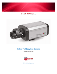
Mounting Troubleshooting This is an indoor camera. It is not suitable for exposure to particles or liquids. No picture after providing power Check the power connection to the power supply to the power outlet for connectivity. Check the power supply voltage. Check all connecting cable and monitors for loose connections. Check the monitor settings Please note the camera’s operating temperature of -10°C ~ 45°C. Avoid using the camera at too high or too low temperatures. Never make the camera face the sun or bright object or you may damage the image sensor. Do not mount the camera near a radiator, heater, or other heat source. Caution: Once power is supplied, do not remove the camera from the mounting base due to risk of electrical shock. This camera uses a standard mounting bracket, sold separately. ELI-EFB / EEFB Analog Full Body Camera The picture has interference or ripples This may be caused by the power supply’s arc, poor quality cable, too long cable, or improper ground connection. The picture background color changes continuously A fluorescent light’s electromagnetic field may cause color roll. Reduce the number of fluorescent lights or increase the distance between the camera and the lights to reduce this effect. Use of a power supply with external sync may solve the problem. Blurred Image Check the dome cover for dirt or imperfections Check the focus to make sure adjusted correctly Check the lens of the camera to make sure it is clean. Only use a dry, clean lens cloth to clean the lens. Never touch with your fingers. This camera accepts lenses with a C/CS lens mount. Lens sold separately. User Manuals and Specification Sheets are available at http://eLineTechnology.com Caution: Before providing power for the camera, please read this Quick Start Guide or the User Manual in detail. Do not attempt to disassemble the camera. If the camera is not functioning properly, please contact your local dealer/installer. eLineTechnology.com On-Screen Display (OSD) Settings Connections On the OSD control device on the back of the body, hit the center button to activate the OSD settings. 1. Use a BNC connector to connect the camera’s VIDEO OUT to the monitor’s (or DVRs) VIDEO IN. Use the following recommendations for cable types and distances: Exposure LENS HBL C/D-WDR ELC/DC BLC/HLI/D-WDR AGC 3D DNR OFF / LOW / MIDDLE / HIGH OFF / LOW / MIDDLE / HIGH SENSE-UP AUTO / OF F / X2 / X4 / X8 / X16 / X32 / X64 / X128 / X256 / X512 EXIT Color WB MODE Day & Night R-Y-GAIN B-Y-GAIN EXIT D&N MODE Function Motion Privacy Setup System Exit ATW / MANUAL / AWC>PUSH / AWC 0-256 0-256 AUTO / COLOR / B&W / EXT MIRROR SHARPNESS LSC MOTION ON / OFF 0-30 ON (0-30) / OFF ON / OFF AREA SEL SENSITI DISPLAY HOLD TIME ALARM EXIT MASK1MASK8 TITLE DPC TOP / BOTTOM / LEFT / RIGHT 0-30 OFF / ICON / TRACE 0-15 Unit: sec ON / OFF OLPF MONITOR GAMA EXIT CAMERA ID COMMUNI LANGUAGE EXIT FACTORY SET SAVE & EXIT EXIT ON / OFF OFF / ON 64 characters OFF / MANUAL:WHITE THR 0255 / BLACK THR 0-255 / DPC LEVEL 0-255 650 / 850 CRT / LCD 0.45 / 0.60 / 1.0 / USER 0-255 PROTOCOL PELCO-D BAUDRATE: 2400 / 4800 / 9600 bps Chinese / English Type of Coaxial Cable Recommended Max Cable Length RG-59/U 250 M 825 ft Maximum Cable Length RG-6/U 500 M 1650 ft RG-11/U 600 M 1980 ft RG-15/U 800 M 2640 ft 2. The power is DC 12V (+/- 10%) / 350mA. Use the following recommendations for cable types and distances: 12V DC Recommended Wire Size and Resistance (68°F) #22 #20 #18 Copper Wire Size #24 2 2 2 2 (0.33 mm ) (0.52 mm ) (0.83 mm ) (AWG) (0.22 mm ) Resistance (Ω/m) 0.078 0.050 0.03 0.018 Resistance (Ω/ft) 0.024 0.015 0.009 0.005 Use the formula below to calculate the power cord and power supply. “L”, “R”, “VA”, “I” shall satisfy the inequality below: 10.8 V DC ≤ VA - 2 (R x I x L) ≤ 16 V DC L = Cord length (m or ft) R = Resistance of copper wire (Ω/m or Ω/ft} VA = DC output voltage of power supply unit I = DC current consumption (A). 3. Connect power supply to the camera’s POWER IN terminal.


