1
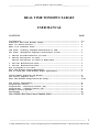
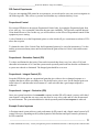
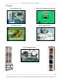
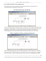
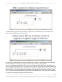
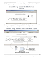
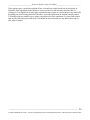
________________________________ Real Time Windows Target User Manual_________________________________
REAL TIME
WINDOWS
TARGET
Control Engineering
2009 / 2010
Dr T P Sattar and Mehdi Zahir
Faculty of Engineering, Science and the Built
Environment
_____________________________________________________________________________________________
0
London South Bank University - Faculty of Engineering Science and Built Environment -Control Systems Lab Room T405
________________________________ Real Time Windows Target User Manual_________________________________
REAL TIME WINDOWS TARGET
USER MANUAL
CONTENTS
PAGE
Introduction-----------------------------------------------------------Simulink’s Real Time Windows Target------------------------------------What is a Device Driver?-----------------------------------------------What is an Interface Card?----------------------------------------------
2-3
4
4
5
ISA Cards, (Industry Standard Architecture or ISA)---------------------- 5
PCI Cards, (Peripheral Component Interconnect or PCI)-------------------- 5
1. The PCI 9112 Multifunction I/O card----------------------------------- 5
2. The PCI 236 Digital I/O Card------------------------------------------ 5
The PCI 236 Digital I/O Card I/O Mode Table--------------------------- 6
3. PCI 230+ Multifunction Card------------------------------------------4. PCI 626 Multifunction Card------------------------------------------How to program an I/O Card----------------------------------------------Real Time Windows Target Experiments------------------------------------How to setup Real Time Windows Target experiments------------------------
6
6
7
8
9
Control Model Libraries and Blocks--------------------------------------- 11
The Control Template File------------------------------------------------ 14
Real Time Windows Target Block-Set Setup--------------------------------- 15-20
PID Control experiments-------------------------------------------------Proportional Control----------------------------------------------------Proportional - Derivative Control (PD)----------------------------------Proportional - Integral Control (PI)------------------------------------Example Control systems-------------------------------------------------Photographs -------------------------------------------------------------
21
21
21
21
21
22
How to build a Real Time Control Simulink Model --------------------------------------------- 23
_____________________________________________________________________________________________
1
London South Bank University - Faculty of Engineering Science and Built Environment -Control Systems Lab Room T405
________________________________ Real Time Windows Target User Manual_________________________________
INTRODUCTION TO REAL-TIME WINDOWS TARGET
The Real-Time Windows Target is a PC solution for prototyping and testing real-time systems (see
figure 1).
The Real-Time Windows Target uses standard and inexpensive I/O boards for PC-compatible
computers. When running your models in real time, the Real-Time Windows Target captures the
sampled data from one or more input channels, uses the data as inputs to your block diagram model,
immediately processes the data, and sends it back to the outside world through an output channel on
your I/O board.
In this environment you can use your desktop PC with MATLAB®, Simulink® and Stateflow® to
create models of physical plant using Simulink blocks.
After creating a model and simulating it with Simulink in NORMAL MODE, you can generate
executable code with Real-Time Workshop®, Stateflow Coder (optional), and the Open Watcom
C/C++ compiler.
Then you can run your application in real time with Simulink EXTERNAL MODE.
Simulink Model of
Real Physical Plant
and I/O Blocks
I/O Card
A/D
Real
Physical
D/A
System
Encoder
Digital
Inputs
Digital
Outputs
Real-Time Kernel
PC or Laptop
Figure 1: PC control of physical system
The Real-Time Windows Target uses a small real-time kernel to ensure that the real-time application
runs in real time. The real-time kernel runs at CPU ring zero and uses the built-in PC clock as its
primary source of time to generate Timer interrupts, achieve precise sampling, and schedule the
executable tasks in multitasking or single-tasking mode. The kernel interfaces and communicates with
I/O hardware using I/O driver blocks, and it checks for proper installation of the I/O board. The Analog
Input, Analog Output, Digital Input, Digital Output, Counter Input, and Encoder Input blocks call the
drivers for input and output. Communication between Simulink and the real-time application is
_____________________________________________________________________________________________
2
London South Bank University - Faculty of Engineering Science and Built Environment -Control Systems Lab Room T405
________________________________ Real Time Windows Target User Manual_________________________________
through the Simulink external mode interface module. This module talks directly to the real-time
kernel, and is used to start the real-time application, change parameters, and retrieve scope data. RealTime Windows Target applications are compiled with the Open Watcom C/C++ compiler.
Integration between Simulink external mode and the Real-Time Windows Target allows you to:
1. Use your Simulink model as a graphical user interface for Signal visualization -- Use the same
Simulink Scope blocks that you use to visualize signals during a non-real-time simulation to
visualize signals while running a real-time application.
2. Parameter tuning -- Use the Block Parameter dialog boxes to change parameters in your
application while it is running in real time.
Typical applications for the Real-Time Windows Target include
1. Real-time control -- Create a prototype of automotive, computer peripheral, and
instrumentation control systems.
2. Real-time hardware-in-the-loop simulation -- Create a prototype of controllers connected to a
physical plant. For example, the physical plant could be an automotive engine. Create a
prototype of a plant connected to an actual controller. For example, the prototyped plant could
be an aircraft engine.
You have already modelled and simulated some dynamic systems of the type shown in figure 2 using
Simulink in Normal Mode i.e. a pure simulation in which a Physical device does not exist.
The investigations in this lab will use Simulink’s External Mode capability to control real physical
systems. The systems in the Control Lab will enable you to study the following types of control:
Process control(Temperature or Flow or Both), Temperature Control( Fan & Heater Module or Peltier
Module), Position & Speed Control of a Servo Mechanism, Magnetic Levitation and Model Lift
Control.
_____________________________________________________________________________________________
3
London South Bank University - Faculty of Engineering Science and Built Environment -Control Systems Lab Room T405
________________________________ Real Time Windows Target User Manual_________________________________
To carry out these investigations you will need to familiarize yourself with Real Time Windows
Target. Brief descriptions are given below. More information can be obtained by running Simulink
and using HELP from Real Time Windows Target.
Simulink’s Real Time Windows Target
This is a Simulink Library that provides an interface between the user and a Real-Time Physical
device. It is a way of creating a model for the system to be controlled by simple Drag & Drop blocks
that make up the system. The use of this Library requires knowledge and understanding of the
Interface Card (I/O Card ) that is used to provide a hardware link between the device to be
controlled and the computer. The Simulation is set to External Mode when an external or physical
device is the Target. Figure 3 shows a typical configuration for feedback control systems. The
Setpoint or Input signal R(s), error signal E(s) obtained from the subtractor, and the controller are
implemented in software (Simulink). The hardware comprises the interface I/O cards (to convert
digital signals to analogue before application to the physical plant, and to convert analogue signals
from the plant to digital signals). These I/O cards have to be linked via Simulink to the Plant.
Real Time Windows Target eliminates the need to write such programs and provides a set of C-code
generators, compilers and Linkers to bypass the programming effort. The user simply makes up the
block representation of the system to be controlled and Simulink generates the C-code and all of the
necessary interactive codes to link the blocks with the Physical system. This is known as TLC or
Target Load Compiler.
Figure 3: Feedback Control System for a Physical
Plant
Real time windows Target, provides a Library of Device Drivers for popular and cheap General
Purpose I/O cards (made by various manufacturers) to speed up the interfacing process for the user.
What is a Device Driver?
A device driver is simply a set of program functions that are written to access ports in the Interface
card. Manufacturers usually provide the software in various Languages such as C, C++, VB, VC++ or
Pascal for DOS and Windows. However, their use requires a proficient programmer in these languages
to make them work.
_____________________________________________________________________________________________
4
London South Bank University - Faculty of Engineering Science and Built Environment -Control Systems Lab Room T405
________________________________ Real Time Windows Target User Manual_________________________________
What is an Interface Card?
This is a physical device that is plugged into a PC’s I/O slots such as ISA or PCI and has a Physical
address within the PC’s I/O memory that enables the user to program and access it. The Card
Manufacturer provides a range of addresses that are selectable by the user to set I/O card’s Physical
address (Base Address). This address range is limited in the case of an ISA card but has no limit in the
PCI versions.
ISA Cards, (Industry Standard Architecture or ISA).
Windows allows the use of any ISA Interface Card as long as it is within the I/O address range and has
a proper windows device driver to access it.
PCI Cards, (Peripheral Component Interconnect or PCI).
PCI cards are given their Base address via plug and play in Windows operating System. This means
that Windows will decide the physical address of the plug and play PCI automatically to make sure that
there are no address conflicts with other devices.
In both ISA & PCI cards, there are typical general purpose devices such as A/D, D/A converters,
Digital Inputs, Digital Outputs, Counters & Timers which are accessible through Ports.
There are no ISA Cards available in the Control Laboratory (T405) as they are becoming
obsolete. There are 4 types of Modern PCI cards used in the Real Time experiments as follows:
1. PCI 9112 Multifunction I/O Card:
16 Channel Bipolar A/D Converter
2 Channel unipolar D/A Converter ( can be made bipolar through external reference voltage)
16 Channel Digital output (fixed)
16 Channel Digital input (fixed)
3 Channel counter and timer
RtWinTgt device driver available.
2. The PCI 236 Digital I/O Card
This board is a 24 bit Generic Digital I/O card which emulates the 8255 chip. The Address map for this
device is:
Base Address
Port A
Port B
Port C
$$$$
Allocated by Windows device manager
Base
Base+1
Base+2
Control Register Base+3
_____________________________________________________________________________________________
5
London South Bank University - Faculty of Engineering Science and Built Environment -Control Systems Lab Room T405
________________________________ Real Time Windows Target User Manual_________________________________
The I/O modes of the board are limited to the following table and the users must choose a mode
carefully to suit the I/O module. The control word (or port setup data ) is output to the control register
to set the ports to the required modes.
The PCI 236 Digital I/O Card I/O Mode Table
3. PCI 230+ Multifunction Card
16 Channel Bipolar A/D converter
2 Channel Bipolar D/A converter
8 Channel Digital Input
8 Channel Digital Output
3 Counter or timer channels
RtWinTgt device driver is based on a separate generic 8255 device and two additional generic
ports. There are however, two subsystems for A/D and D/A models developed to provide
access to the I/O card from Simulink.
4. Sensoray PCI 626 Multifunction Card
This card has numerous devices:
16 channel Bipolar 16 bit A/D converters
4 Channel Bipolar 12 bit D/A converters
24 Digital outputs
24 Digital inputs
6 x 24 bit Counters/timers for Encoder inputs
Interrupt generation
Batter backup of all timers/counters
_____________________________________________________________________________________________
6
London South Bank University - Faculty of Engineering Science and Built Environment -Control Systems Lab Room T405
________________________________ Real Time Windows Target User Manual_________________________________
How to program an I/O Card
This requires careful study of the data in the Manuals provided by the Manufacturer. The operation of
each device is described in detail in the Manuals. The physical address Map for each device is given in
the Address and Mode of operation tables.
Some I/O cards need to be configured before they are plugged into a PC I/O slot. A Card may be
configured (depending on what devices are available) as follows:
Setting up the following using either a bank of switches or jumpers:
Base address
A/D converter’s input mode: Bipolar or unipolar
A/D converter’ s operation mode: software trigger, external trigger or Interrupt driven.
D/A converter’s output mode: Bipolar or unipolar
Digital I/O ports input/output mode: strobe or none-strobe trigger.
Counter/Timers Internal/external clock, trigger mode: Internal external, Interrupt.
Once the card is plugged in, upon power up the logic on the card will read the switches/jumpers and
configure the Cards operation.
On some I/O cards all the configuration can be done via software codes sent to the control registers.
PCI card .pdf manuals are available for download from the ECCE3 server:
http://ecce3.lsbu.ac.uk/staff/zahirm/controllab/CE3/PCICard Manuals
_____________________________________________________________________________________________
7
London South Bank University - Faculty of Engineering Science and Built Environment -Control Systems Lab Room T405
________________________________ Real Time Windows Target User Manual_________________________________
Real Time Windows Target Experiments
The following control investigations will familiarize you with Real Time Windows Target. The
Simulink Models for these experiments can be found in the Matlab Path:
C:/Documents & Settings/Control.T405../My Documents/Matlab
Note:
In addition to the files shown below, there is a Template file, ControlTemplate.mdl which is
configured for real time control. All files are READ ONLY. You should open ControlTemplate.mdl,
only when developing a Model from scratch, and use Save as from the file Menu with a filename of
your choice. You must not modify the settings in any of the Blocks that are already setup in the
experiments. You may open the blocks to inspect and learn from them.
Before you attempt to Run these simulations, you must learn how to run Simulink in External
Mode. This is shown on the next page/s.
1) Process Control Unit (PCU) Rig. This unit is equipped with devices for Temperature Control,
Flow Control and Flow Cooling heat exchanger.
Model File: PCUTEST.mdl
2) Fan and Heater Module. Temperature Control.
Model File: FANHEATERTEST.mdl
3) Peltier effect Temperature Control Module. Rapid Temperature Control in the Range (8-40
degrees centigrade)
Model File: PELTIERTEST.mdl
4) Coupled Tanks Rig
Model File: TANKTEST.mdl
5) SRV 33-100 Analogue/Digital Servo
Model File: SRV33100.mdl
6) ES151 Servo units – 1 & 2
Model File: ES151Demo.mdl
7) Magnetic Levitation Rig. Suspension of a Ferrous Ball in a Magnetic Field.
Model File: ManeticLevitation.mdl
8) Elevator Control.
Model File: ELEVATORTEST.mdl
9) Heat Exchanger.
Model File: HEATEX.MDL
10) Ping Pong Ball suspension.
Model File: PINGPONG.MDL
You can also open the Demo files related to the experiments and Run them.
Backup all your files on Memory Stick.
_____________________________________________________________________________________________
8
London South Bank University - Faculty of Engineering Science and Built Environment -Control Systems Lab Room T405
________________________________ Real Time Windows Target User Manual_________________________________
How to Run Simulink and Real Time Experiments
Logon to a Computer connected to one the Rigs or Modules
Once the desktop is visible, double click on Matlab7.0 Icon. You must wait for Matlab to be loaded as
this is a slow process. Matlab’s command window is displayed as shown below:
Now click on the Simulink Browser Icon:
Simulink Browser window will be displayed as shown next:
_____________________________________________________________________________________________
9
London South Bank University - Faculty of Engineering Science and Built Environment -Control Systems Lab Room T405
________________________________ Real Time Windows Target User Manual_________________________________
At this point you will see the various libraries that are available. These have sub folders and you may
open them by clicking on the Plus Sign to the left of the library icon. Various blocks and Libraries are
displayed but only a few of these are relevant to your experiment. On the next page some of the
commonest libraries and their Model blocks are shown.
_____________________________________________________________________________________________
10
London South Bank University - Faculty of Engineering Science and Built Environment -Control Systems Lab Room T405
________________________________ Real Time Windows Target User Manual_________________________________
Control Model Libraries and Blocks
Shown as: Library / Blocks
Commonly Used Blocks / constant, subtractor, multiplexer,
Real time windows target / digital input, output, analogue input, output etc
User Defined Functions / function
Sinks and sources / scope, display, function generator
Simulink extras / additional Linear / PID controller
Signal routing / manual switch
Ports and Subsystems / subsystem, enabled subsystem, triggered subsystem
You may need to open other libraries and search for blocks that could be used for developing your
Control Model for your experiment.
Now click on the Simlulink Browser window: File and Open
then click on the Model file related to your experiment under Work/CE3 folder
Select and click on Open, the Model file related to your experiment will be loaded.
_____________________________________________________________________________________________
11
London South Bank University - Faculty of Engineering Science and Built Environment -Control Systems Lab Room T405
________________________________ Real Time Windows Target User Manual_________________________________
You should see the model file blocks displayed.
The following pictures are only examples and may not be related to your experiment.
This is a magnified version of the Menu Bar
1
2
3
4
5
NOTE:
It is important at this stage to note the following icons and their meaning. From left to right the
icons you are concerned with are:
1.
2.
3.
4.
5.
Run simulation on Target.
Connect to Target
Run time for real time control
Real time control mode(External)
Build the model. i.e generate C-code, compile and link.
Build this model by clicking on Icon 5. Matlab’s command window will be automatically maximized
and will display the stages in C-code generation, compilation and the link process. If there are no errors
and the logic of the model meets specifications and constraints imposed by Simulink, then the final
message “Successful Completion ……….”, will be displayed at the end of the process.
_____________________________________________________________________________________________
12
London South Bank University - Faculty of Engineering Science and Built Environment -Control Systems Lab Room T405
________________________________ Real Time Windows Target User Manual_________________________________
The next step is to connect the model to the Target i.e the Physical system to be controlled. Now click
on Icon number 2. There will be a short delay and the Icon will be displayed as if Unselected and will
reappear in Bold. The Icon number 1 (Right Arrow Icon) will now be highlighted. Click on this Icon,
to Run the Control Model. Once the Model is running the elapsed simulation time will be displayed at
the bottom of the model window. Icon Number 1 now changes to a Bold square Icon which means
Stop Simualtion. You may stop the simulation at any time or wait until the simulation time runs out.
So the process to follow in order is:
1.
2.
3.
4.
Create a model and save it.
Build the model
Connect to target
Run Simulation.
BEWARE!
Every time a model is changed, i.e blocks are added or modifications made to the way it is set up
it must be Saved and Rebuilt. You must not attempt to modify the model whilst real time control
is Running as this will cause the system to crash. You must also be careful with clicking on
Labels displayed with each block as Simulink will interpret this as a modification, which is not
allowed during a Run and will cause the system to crash.
Matlab and Simulink are Multitasking and will give the highest priority to the Running real time
control. Therefore, it is essential that you do not also attempt to run any other programs or tasks
under windows environment. This may cause unpredictable results and freeze your PC.
_____________________________________________________________________________________________
13
London South Bank University - Faculty of Engineering Science and Built Environment -Control Systems Lab Room T405
________________________________ Real Time Windows Target User Manual_________________________________
The Control Template File
The ControlTemplate.mdl Model file contains all the necessary settings for a Real Time Control
simulation. Its parameter settings must not be modified, however you may modify only the Simulation
Runtime of the Model. Use this file only when developing a Model from Scratch.
There are several types of Solvers or Output Differential Equations (ode?) used to configure the
Models for various uses. However, the Real Time Control is restricted to Ode4 Solver. The template
file shows this at the bottom right hand side of the Model window.
It is not necessary to show all the Subfolder information in the Configuration Parameters dialogue
window, but you may look at them yourself. In the picture below only the solver information is shown.
Check this is ticked
You may change Simulation
Time.
You may Look at these
but do not modify
their contents
_____________________________________________________________________________________________
14
London South Bank University - Faculty of Engineering Science and Built Environment -Control Systems Lab Room T405
________________________________ Real Time Windows Target User Manual_________________________________
Real Time Windows Target Block-Set Setup
Please ensure that you follow the steps shown below carefully. A picture is given for every step to ease
the setup process. Run Matlab and Simulink, open the ControlTemplate.mdl file from the Simulink
Library Browser Window. Then click on Real Time Windows Target Library, so that you have the
following picture.
Go to the ControlTemplate Menu Bar click File and use Save as to save the Model with a new name
controlmodel1.mdl. The new name will be displayed at the top of the Model File Window.
_____________________________________________________________________________________________
15
London South Bank University - Faculty of Engineering Science and Built Environment -Control Systems Lab Room T405
________________________________ Real Time Windows Target User Manual_________________________________
Now drag and drop a Digital Output block from the Library to the model file window.
First, an I/O device must be selected from Simulink’s device driver libraries. Now double click on the
Digital output Block to set its parameters.
_____________________________________________________________________________________________
16
London South Bank University - Faculty of Engineering Science and Built Environment -Control Systems Lab Room T405
________________________________ Real Time Windows Target User Manual_________________________________
If an I/O card is not installed, you will see the message <<no board installed>> otherwise the Name of
the I/O card will be displayed such as Generic 8255 etc. This is the board set up for your experiments.
Do not install any device at this stage.
The Block parameters for a Digital Output can be set from this window.
_____________________________________________________________________________________________
17
London South Bank University - Faculty of Engineering Science and Built Environment -Control Systems Lab Room T405
________________________________ Real Time Windows Target User Manual_________________________________
This picture below shows the stages in the setup procedure.
You may now click on Board Setup button and go to the next page.
_____________________________________________________________________________________________
18
London South Bank University - Faculty of Engineering Science and Built Environment -Control Systems Lab Room T405
________________________________ Real Time Windows Target User Manual_________________________________
Use the information provided in the Excel spreadsheet file for your experiment to check the Ports
Address 2C0 Hex and Mode set up for each of the Ports A, B & CL ( Lower nibble ), CH ( Higher
nibble ). You may Click The Test Button to check that the Board is present and functioning properly.
Click OK and continues to the next page.
_____________________________________________________________________________________________
19
London South Bank University - Faculty of Engineering Science and Built Environment -Control Systems Lab Room T405
________________________________ Real Time Windows Target User Manual_________________________________
This part of the setup is concerned with the sample time, the output channel/s used for the device/s to
be controlled, the Initial and Final values of the Digital Output/s.
To setup this properly depends on the device that is connected to the channel/s. If a device such as a
D/A converter is connected to the channel, the channel mode is set to Byte to output a byte of data to
the correct channel numbers starting from the Specified Channel. If the device is activated by only 1
bit i.e a single channel then the channel mode is set to Bit mode.
You must check the experiment’s Excel file to clarify theses for yourself. However all the devices are
setup already. Once you click OK the Digital Output Block setup is complete.
Note:
A Digital input block is setup in exactly the same way. But the block is used to read a Sensor or
receive information from a feedback source.
_____________________________________________________________________________________________
20
London South Bank University - Faculty of Engineering Science and Built Environment -Control Systems Lab Room T405
________________________________ Real Time Windows Target User Manual_________________________________
PID Control Experiments
If you are investigating PID control in an experiment, you are advised to carry out your investigation in
the following order. This will save you time and eliminate any confusion that may occur.
Proportional Control
First setup a PID block to investigate Proportional Control only, by setting the Proportional gain from
a low value say 1 to a reasonable value that does not cause instability. The Derivative and the Integral
Gains should be set to Zero. In this way you will be able to see the effect of Proportional control on the
equipment you are testing.
A rule of thumb is to set the Proportional gain to a value which will give a maximum overshoot of 25%
above the set-point.
To obtain the value of the Critical Gain, the Proportional gain may be varied in increments of 1 or less
and the system tested many times until such time that the gain reaches its Critical value and becomes
unstable.
Proportional – Derivative Control (PD)
To reduce oscillations the derivative Gain can be increased then from a very low value of 0.01 and
thereafter in increments of 0.01 and the system tested repeatedly until such time that the oscillations in
a system are reduced or eliminated. The Integral gain should be set to zero.
Proportional – Integral Control (PI)
Setup the PID blocks gains to a proportional gain that gives either a slow or damped response or a
response that has an offset or tracking error. Set the derivative gain to zero. Set the Integral gain to an
initial value of 1 and thereafter in increments of 1 until such time that a good output response is
achieved.
Proportional – Integral – Derivative (PID)
Once your system has achieved a reasonable response in either PD or PI control, you may add a third
term control i.e the gain that was set to zero may now be set to a low value and its value incremented
by small amounts. The system should then be tested repeatedly until the best response is achieved.
Example Control systems
A Position control system achieves good performance by PD control, and a Speed control system by PI
control. However, depending on the systems dynamics both Position and Speed control systems may
be PID controlled.
_____________________________________________________________________________________________
21
London South Bank University - Faculty of Engineering Science and Built Environment -Control Systems Lab Room T405
________________________________ Real Time Windows Target User Manual_________________________________
Photographs
Process Control Unit
Peltier effect Temperature Controller
Fan Heater Module
ES151 Analogue Servo
SRV-33100 Digital Servo
Coupled Tanks
Elevator
_____________________________________________________________________________________________
22
London South Bank University - Faculty of Engineering Science and Built Environment -Control Systems Lab Room T405
________________________________ Real Time Windows Target User Manual_________________________________
How to build a Real Time Control Simulink Model
The following set of pictures, were shown in the demonstration and are also included in all
experiments related to Simulink Real Time Control.
A typical closed loop model is shown above where a slider gain is used to change the proportional gain
in the system. The simulation is in Normal mode with a Step input. Note that the output of the system
modelled by a transfer function is used to provide negative unity feedback. This Feedback is a
fictitious signal and does not represent the behaviour of the actual output sensor in the system.
The above and subsequent pictures show that in External Mode / Real time control, G(S) is replaced
with an actual system. This requires the use of an Interface Card to connect the system to a computer.
Before this is done, a number of changes should be made to allow correct signalling to the interface.
_____________________________________________________________________________________________
23
London South Bank University - Faculty of Engineering Science and Built Environment -Control Systems Lab Room T405
________________________________ Real Time Windows Target User Manual_________________________________
A PID controller is placed in the forward path, followed by a Saturation block to limit the control
signal to the signalling range of the Interface.
Now Real time control blocks are inserted into the model to allow the control signal to be output and
also the feedback from the System to be read. These can be Analogue Outputs(D/A
converters)/Analogue Input blocks(A/D converters) or Digital Output/ Input blocks depending on the
device used in the external system. These devices have input and output range specifications defined in
the Actual Block. The signal range is specified by the manufacturer and can be seen by double-clicking
the block itself. Therefore the saturation block ranges must be specified to match the real time control
blocks. Real Time Control Blocks are provided in a test Model file for each experiment in the lab.
You must not change the parameters in these blocks.
_____________________________________________________________________________________________
24
London South Bank University - Faculty of Engineering Science and Built Environment -Control Systems Lab Room T405
________________________________ Real Time Windows Target User Manual_________________________________
The following picture completes the creation of the model by including the real time control blocks.
We can now see how the original fictitious system G(S) differs from the Actual system as shown in the
following picture. G(S) below is now the Physical connection to a real System.
_____________________________________________________________________________________________
25
London South Bank University - Faculty of Engineering Science and Built Environment -Control Systems Lab Room T405
________________________________ Real Time Windows Target User Manual_________________________________
These pictures give a general description of how a closed loop control model can be developed in
Simulink. Each experiment in the lab has its own set of devices and relevant I/O blocks that are
Analogue I/O or Digital I/O or both. Some experiments may require two closed loops in one model file
depending on what is being controlled. Therefore, each experiment must be studied carefully and its
Test Model used in a sensible way to achieve the objectives of the experiment. You may find at times
that not all of the blocks provided in the Test Model are necessary and you may delete these and use
only what is needed.
_____________________________________________________________________________________________
26
London South Bank University - Faculty of Engineering Science and Built Environment -Control Systems Lab Room T405