1
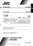
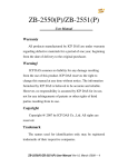
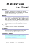
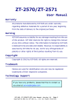
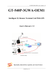
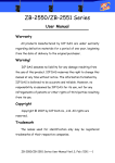
IR-712A Universal IR Learning Remote Module User Manual v1.0 www.icpdas.com IR-712A Universal IR Learning Remote Module (Ver. 1.0, Nov/13/2012) Warranty All products manufactured by ICP DAS are under warranty regarding defective materials for a period of one year from the date of delivery to the original purchaser. Warning ICP DAS assumes no liability for damages resulting from the use of this product. ICP DAS reserves the right to change this manual at any time without notice. The information furnished by ICP DAS is believed to be accurate and reliable. However, no responsibility is assumed by ICP DAS for its use, or for any infringements of patents or other rights of third parties resulting from its use. Copyright Copyright 2012 by ICP DAS. All rights are reserved. Trademark The names used for identification only may be registered trademarks of their respective companies. IR-712A Universal IR Learning Remote Module (Ver. 1.0, Nov/13/2012) 1 Contents 1. Introduction .......................................................................................3 1.1 1.2 Features .................................................................................................. 4 Applications ............................................................................................. 4 2. Hardware ...........................................................................................5 2.1 2.2 2.3 Specifications .......................................................................................... 5 Appearance ............................................................................................. 6 Pin assignments ...................................................................................... 7 2.4 Wire connection....................................................................................... 8 2.4.1 RS-232 connection ........................................................................... 8 2.4.2 RS-485 connection ........................................................................... 9 2.4.3 Jack Plug of IR Output Cable ......................................................... 10 2.4.4 Power Connection .......................................................................... 10 2.5 Watchdog Timer ..................................................................................... 11 2.6 Firmware Update DIP Switch ................................................................ 12 2.6.1 Update Firmware Mode .................................................................. 12 2.6.2 Firmware Operation Mode.............................................................. 13 2.7 LED Indicators ....................................................................................... 14 3. Software...........................................................................................15 3.1 3.2 The Configuration Tool– IR-712A Utility ................................................. 15 IR-712A Utility........................................................................................ 16 3.2.1 Menu .............................................................................................. 16 3.2.2 Open/Close COM port .................................................................... 20 3.2.3 Set Device & IR Command Quantity .............................................. 20 3.2.4 Test and Save Learned IR Commands .......................................... 22 3.2.5 Test IR commands in IR-712A........................................................ 24 4. Learning IR command Example .....................................................25 4.1 4.2 4.3 4.4 4.5 4.6 4.7 4.8 IR-712A Communication settings .......................................................... 25 Set the Devices and IR commands Quantity ......................................... 26 Learn and Test IR Commands ............................................................... 27 Saving the Learned IR Commands to a File .......................................... 28 Download the IR Learning Commands to the IR-712A.......................... 28 Test the IR commands saved in the IR-712A ........................................ 28 Load the IR Learning Commands from a File ........................................ 29 Load IR Learning Commands from the IR-712A ................................... 29 5. Modbus Registers for IR-712A .......................................................30 6. Technical support ...........................................................................31 IR-712A Universal IR Learning Remote Module (Ver. 1.0, Nov/13/2012) 2 1. Introduction The Intelligent Home and Building Automation are becoming the hot topics recently in the world. Many countries are devoted to development and promotion in this field. There are many kinds of consumer electronics and home appliances in the market applying the IR remote control function because of its mature technology and low cost. However, these appliances are usually equipped with their own remote controls using diverse IR protocols which are not unified to a standard. If these IR commands of different appliances can be collected and integrated to the control interfaces, it is possible to implement the automation application for a better living experience. IR-712A is a universal IR learning remote module which can learn IR remote commands of diverse electronic devices. The learning commands (max. 224) can be stored in the module or saved to a file. IR-712A supplies 2 IR output channels for individual or simultaneous control on multiple devices. The accompanied RS-232 and RS-485 interfaces with Modbus/RTU protocol provide more flexible expansion and control on the module. Besides, IR-712A software utility provides users with easy configuration, learning, test and storage of IR commands. As a replacement of IR remote controls and a module that can be easily integrated with Modbus master devices (e.g. PAC, PLC, PC… etc.), IR-712A is well-suited for smart home and building automation. Fig. 1-1: IR-712A application architecture. IR-712A Universal IR Learning Remote Module (Ver. 1.0, Nov/13/2012) 3 1.1 Features [IR-712A] 2 IR output channels for controlling multiple devices. 1 IR learning input. Supports 6 learning IR carrier frequencies: 32.768、36、37.037、38、40 and 56 kHz. Can learn and store 224 IR commands. Supports RS-232 and RS-485 serial interface. Supports Modbus/RTU protocol (FC06 and FC16). Assignable Modbus Network IDs: 1 ~ 247 Baud rate settings: 9600, 19200, 38400, 57600 and 115200 bps. Configurable NONE / ODD / EVEN parity and 1 or 2 stop bits. Provides transmitting/learning and power indication LEDs. Built-in Watchdog. RoHS Compliance. [Utility] Configuration of IR command quantity. IR commands learning and testing. Save IR learning commands to files. Get / Set IR learning commands from / to IR-712A. Reference to Modbus commands. Set / Reset basic settings of IR-712A. Supports Windows XP, Vista and Windows 7 with .NET framework 4.0. 1.2 Applications Home Entertainment Devices Video Conferencing System Surveillance System e-Classroom service Lighting Scenario Control Home and Building Automation IR-712A Universal IR Learning Remote Module (Ver. 1.0, Nov/13/2012) 4 2. Hardware 2.1 Specifications IR-712 IR Interface IR Output Ch. 2 channels with 3.5 mm audio jack IR Input Ch. 1 channel. Supports 6 IR carrier frequencies: 32.768, 36, 37.037, 38, 40, 56 kHz. (can learn 224 IR remote commands) UART Interface Connector 8-pin (RS-485, RS-232, power) screw terminal connector COM1 RS-232 (TxD, RxD, GND) COM2 RS-485 (DATA+, DATA-) Baud Rate (bps) 9600, 19200, 38400, 57600, 115200 Protocol Modbus/RTU (slave) LED Indicator LED 2 LEDs: TR (IR Transmitting)/LN (IR Learning) and PWR (Power) Power Power Supply +10 ~ +30 VDC Power Consumption 1.8 W Max (OP mode) DIP Switch FW (firmware update mode) / OP (firmware operation mode) Mechanism Installation DIN-Rail Dimensions 52 mm x 93 mm x 27 mm (W x H x D) Environment Operating Temperature -25 ℃ ~ +80 ℃ Storage Temperature -30 ℃ ~ +85 ℃ Humidity 10 ~ 90% RH, non-condensing IR-712A Universal IR Learning Remote Module (Ver. 1.0, Nov/13/2012) 5 2.2 Appearance Fig. 2-1: The front view of the IR-712A. IR-712A Universal IR Learning Remote Module (Ver. 1.0, Nov/13/2012) 6 2.3 Pin assignments ● IR output channels and learning input IR Output 1 ~ 2:3.5 mm audio jack Fig. 2-2: IR output 3.5 mm audio jack and learning input hole (front/bottom view). ● Communication terminal Table 2-1: IR-712A terminal pin assignments Screw terminal connecter Pin No. Description 1 DATA+ 2 DATA- 3 GND (ground) 4 TxD 5 RxD 6 N/A 7 GND (ground) 8 +Vs Interface RS-485 RS-232 N/A Fig. 2-3: Screw terminal connector Power IR-712A Universal IR Learning Remote Module (Ver. 1.0, Nov/13/2012) 7 2.4 Wire connection The IR-712A supports 2 serial communication interfaces: RS-232 and RS-485 ports. Only one interface can be used at the same time. The default interface is RS-232 port. 2 IR outputs at the bottom are 3.5 mm audio jacks. Note: The IR-712A utility can help users to change the serial communication port (RS232/RS-485). The TR/LN LED can indicate which port is used in the beginning 3 seconds after power-cycling the IR-712A. 2.4.1 RS-232 connection The wire connection for IR-712A’s RS-232 port is shown in Fig. 2-4. Fig. 2-4: RS-232 wire connection. Please refer to Fig. 2-6 if the RS-232 connection cable (e.g. CA-0910, Fig. 2-5) is applied. If there is no DB9 serial port on the host PC, it is recommended to use USB to RS-232 converter (e.g. I-7560 or I-7561) to extend the serial port. Fig. 2-5 RS-232 connection cable (CA-0910) IR-712A Universal IR Learning Remote Module (Ver. 1.0, Nov/13/2012) 8 Fig. 2-6: Wire connection between PC and IR-712A using CA-0910. 2.4.2 RS-485 connection The RS-485 wire connection between the IR-712A and RS-485 host device is depicted in Fig. 2-7. Fig. 2-7: RS-485 wire connection. The USB to RS-485 converter (tM-7561 or I-7561) is recommended for the host PC to test and configure the IR-712A. IR-712A Universal IR Learning Remote Module (Ver. 1.0, Nov/13/2012) 9 2.4.3 Jack Plug of IR Output Cable It is necessary to use 3.5 mm audio jack plug for the IR output jack of IR-712A. IR712A supports the jack plug of TRS and TS connectors as shown in Fig. 2-8 and Fig. 2-9. The wire connection between the connector and IR LED should be also considered. Fig. 2-8: TRS connection Fig. 2-9: TS connection 2.4.4 Power Connection IR-712 consumes the power of +10~+30 VDC. The wire connection for the power is shown in Fig. 2-10. Fig. 2-10: Wire connection for the power. IR-712A Universal IR Learning Remote Module (Ver. 1.0, Nov/13/2012) 10 2.5 Watchdog Timer Watchdog timer is a kind of timer to reset IR-712A while there is some error occurred in the system and the recovery is not possible within a short time (several milliseconds). Users can open the case of IR-712A and adjust the JP1 to enable or disable the watchdog timer as depicted in Fig. 2-11. The default setting to the watchdog timer is “Enable”. Enable (default) Disable Figure 2-11: JP1 for the watchdog timer of IR-712A. IR-712A Universal IR Learning Remote Module (Ver. 1.0, Nov/13/2012) 11 2.6 Firmware Update DIP Switch There is a DIP switch at the lateral of the IR-712A’s case. It is for the setting of the firmware update mode. The following explains how to use the DIP switch. 2.6.1 Update Firmware Mode Push the DIP switch to the “FW” position as shown in Fig. 2-12. The IR-712A will be in the update firmware mode after cycling the power. Users have to update the firmware by the RS-232 port of the IR-712. Fig. 2-12: DIP switch in “FW” position. To update the firmware, users can click the menu [Tool] -> [Update Firmware to IR712A] from the IR-712A Utility to launch the firmware update tool. Please follow the below steps to finish the update firmware procedure, which is also depicted in Fig. 213. (1) Click “COM” radio button and select “COM Port” of the host PC connected to the RS-232 port of IR-712A. (2) Click “Browser” to find the firmware file, e.g. ir712A_vx_xx.fw. (3) Click “Firmware Update” button to start the update procedure. The result of the update would be shown in “Firmware Update” section. Note: 1. After updating the firmware, remember to push the switch to “OP” mode and power cycle the IR-712A to run in operation mode. 2. Updating Firmware would not change the serial communication settings and IR commands saved in the IR-712A. IR-712A Universal IR Learning Remote Module (Ver. 1.0, Nov/13/2012) 12 1 2 3 Fig. 2-13: Update firmware of IR-712A. The firmware of IR-712A can be downloaded from: ftp://ftp.icpdas.com/pub/cd/usbcd/napdos/ir-712A/firmware/ The Firmware_Update_Tool can be downloaded from: ftp://ftp.icpdas.com/pub/cd/usbcd/napdos/ir-712A/software/fw_update_tool/ 2.6.2 Firmware Operation Mode Push the DIP switch to the position of “FW” as shown in Fig. 2-14, IR-712A will be set in the Firmware Operation Mode after cycling the power. In this mode (default), IR712A can learn IR commands from remote controls as well as be configured by the utility and receive Modbus commands from the master devices. Fig. 2-14: Push the switch to “OP” mode IR-712A Universal IR Learning Remote Module (Ver. 1.0, Nov/13/2012) 13 2.7 LED Indicators There are two LEDs in the IR-712A to show different operating states. The meanings of these states are described in Table 2-2. Table 2-2: The description of LEDs for IR-712A LED TR / LN PWR ALL LEDs IR-712A Status LED Status Use RS-232 Blinks 3 times after power-on Use RS-485 Turned on for 3 seconds after power-on Serial Communication Weakly blinking Emitting IR Commands On (during emitting IR signal) IR Learning Mode On IR Learning Finished Off Power is normal On Power Failure Off Firmware Operation Mode TR/LN => OFF; PWR => ON Note: Push DIP switch to OP position and restart IR-712A. Update Firmware Mode TR/LN and PWR => blinking Note: Push DIP switch to FW position and restart IR-712A. (Normal) (Update firmware) IR-712A Universal IR Learning Remote Module (Ver. 1.0, Nov/13/2012) 14 3. Software 3.1 The Configuration Tool– IR-712A Utility IR-712A Utility is used for setting the IR-712A’s parameters and learning IR commands. It is the program executed in the environment of .NET Framework 4 client profile on Microsoft OS. IR-712A Utility on the host PC can communicate with IR-712A via the RS-232 or RS-485 interface. Users can download the IR-712A Utility from: ftp://ftp.icpdas.com/pub/cd/usbcd/napdos/ir-712A/software/Utility/ If the environment of .NET Framework 4 client profile is not available on the Microsoft OS, please download and install the redistributable packages as follows: Web Installer http://www.microsoft.com/download/en/details.aspx?id=17113 Standalone Installer http://www.microsoft.com/download/en/details.aspx?id=24872 Fig. 3-1: The main window of IR-712A utility. IR-712A Universal IR Learning Remote Module (Ver. 1.0, Nov/13/2012) 15 3.2 IR-712A Utility 3.2.1 Menu Table 3-1 lists the menu items in the IR-712A Utility. Table 3-1: The items of menu. Item File Sub Item Load IR Commands from File Unload IR Commands Save IR Commands to File Exit Download Download IR Commands to IR-712A Load IR Commands from IR-712A Setting IR-712A Basic Settings Reset Basic Settings on IR-712A Tool Update Firmware to IR-712A Help About IR-712A Utility (1) File ‧Load IR Command from File The IR command file obtains the IR learning data. The filename extension is IRD. Click this item would pop up an Open File Dialog for users to find and load the IR command file. ‧Unload IR Commands This function would clear all the IR learning commands temporarily buffered in the items of the “Device Name” and “Command Name” combo boxes in the section of the “Test and Save Learned IR Commands.” The quantity and values of the devices and IR commands are reset to the default. ‧Save IR Commands to File This item provides a Save File Dialog to save the IR learning commands to an IRD file. ‧Exit Exit and close the utility. IR-712A Universal IR Learning Remote Module (Ver. 1.0, Nov/13/2012) 16 (2) Download ‧Download IR Commands to IR-712A This item can download the IR learning commands in the utility to the flash memory of the IR-712A. The IR commands would be retained in the module even without power supply. Clicking this item will show a download progress window and close itself after the download is finished. Fig. 3-2: Download the IR commands to the IR-712A. ‧Load IR Commands from IR-712A This item provides the function to load all IR commands saved in the IR-712A to the utility. Clicking this item will show a loading progress window and close itself after the loading is finished. Fig. 3-3: Load the IR commands from the IR-712A. (3) Setting ‧IR-712A Basic Settings Click this item to open the window of basic parameter settings as shown in Fig. 3-4. Fig. 3-4: The basic settings window for IR-712A. IR-712A Universal IR Learning Remote Module (Ver. 1.0, Nov/13/2012) 17 These settings include: [1] COM Port : The COM port of IR-712A. (RS-232/RS-485, default: RS-232) [2] Baud Rate : The baud rate of the COM port (9600~115200 bps,default: 115200) [3] Parity : Parity bit (NONE / ODD / EVEN,default:NONE) [4] Data Bits : Data bit (This value is fixed in 8) [5] Stop Bits : Stop bit (1 / 2, default:1) : Modbus Network ID (1~247, default: 1) : The max space time in an IR protocol (Fig. 3-5). For example, GapTime should be set to the value greater than 40 ms to learn IR commands successfully for the Sharp remote control. (6 ~ 65 ms, default:36 ms) [6] Net ID [7] GapTime Figure 3-5 A complete IR Command with a large Gap Time. [8] MB Cmd Resp Delay Time: The delay time before the IR-712A responses each request from the Modbus master devices (Modbus command response delay time: 0 ~ 60 ms; default: 1 ms) The “Get Setting” button will be executed once when the “Basic Settings” window is opened in the beginning. Three buttons located at the right side of the window are described in the Table 3-2. Table 3-2: Three buttons in the window of basic settings Button Name Description Get Setting Get the current basic parameter settings of IR-712A. Set Temporarily Set the settings of IR-712A to the parameters selected in the window temporarily. Cycling the power will restore IR-712A to previous settings. Set Permanently Set the settings of IR-712A to the parameters selected in the window. IR-712A will retain the settings after power cycling. IR-712A Universal IR Learning Remote Module (Ver. 1.0, Nov/13/2012) 18 ‧Reset Basic Settings on IR-712A If it is failed to communicate with IR-712A and the record of basic settings is lost, click this item to open the reset window as shown in Fig. 3-6. The steps of reset are as follows: (1) Connect PC to the RS-232 port of IR-712A and click “Open” button in the utility to open the COM port of PC. (2) Click Reset button within 3 seconds after cycling the power of IR-712A. (3) A dialog as Fig. 3-7 shows that the resetting to default values is done. Notice that the parameters resetting is temporary. Please go to “IR-712A Basic Settings” interface and click “Set Permanently” button to retain the settings. Fig. 3-6: IR-712A reset window Fig. 3-7: Reset to default settings temporarily. (4) Tool ‧Update Firmware to IR-712A Launch the “Update Firmware Tool”. Please refer to section 2.4.1 for more information. (5) Help ‧About IR-712A Utility This item will show a window which contains the version numbers of the utility and the IR-712A’s firmware. The firmware version will be indicated when the utility can communicate with the IR-712A module. IR-712A Universal IR Learning Remote Module (Ver. 1.0, Nov/13/2012) 19 3.2.2 Open/Close COM port After the serial wire connection is established between IR-712A and host PC, users can click “Open” button to open COM port of the PC. The parameters of the serial communication on the utility should be the same as the settings in the IR-712A. Fig. 3-8: Open/Close COM section The settings of the serial interface are described as follows: [1] COM Port [2] Baud Rate : The COM port of IR-712A. (RS-232/RS-485, default: RS-232) : The baud rate for the COM port (9600~115200 bps,default: 115200) [3] Parity : Parity bit (NONE / ODD / EVEN,default:NONE) [4] Data Bits : Data bit (This value is always 8) : Stop bit (1 / 2, default:1) : Modbus Network ID of IR-712A (1~247, default: 1) [5] Stop Bits [6] Net ID 3.2.3 Set Device & IR Command Quantity The IR device & command quantity for learning can be configured in this section. Please click “Set Device & IR Command Quantity” button (Fig. 3-9) to set them up in three steps (Fig. 3-10 ~ Fig. 3-13). Fig. 3-9: Configure IR command quantity for IR learning. IR-712A Universal IR Learning Remote Module (Ver. 1.0, Nov/13/2012) 20 ● Step 1: Set the IR device quantity The max quantity of controlled devices is 11. This function is convenient for users to manage IR commands in groups as shown in Fig. 3-10. Fig. 3-10: The quantity setting of the device (Step1). ● Step 2: Define the device names and set the IR commands quantity This step (Fig. 3-11) can set the names of the devices and the quantity of the IR command. The prefix number of each device name is the device serial number. The quantity of the IR command cannot exceed 224, or the utility would pop up an error message box and show the remaining quantity for configuration (Fig. 3-12). Fig. 3-11: Define the name and the quantity of the IR commands (Step2). Fig. 3-12: Error message box for exceeding total IR commands Qty. IR-712A Universal IR Learning Remote Module (Ver. 1.0, Nov/13/2012) 21 ● Step 3:Comment the IR command name This step provides the interface to comment each IR command with a name. It is convenient to know the function of an IR command from the name. The prefix number of each IR command name means the serial number saved in the IR-712A and can be a reference in the Modbus command to the IR-712A. Fig. 3-13: Comment the IR command name (Step3). 3.2.4 Test and Save Learned IR Commands This section provides the function of enabling IR learning mode, saving IR commands temporarily and testing the learned IR commands as shown in Fig. 3-14. Fig 3-14: Test & save learned IR commands section. IR Learning Mode This interface (Fig.3-15) provides “Learn On” and “Learn Off” buttons. After clicking the “Learn On” button, the IR-712A would turn into IR learning mode and the TR/LN LED is turned on to wait for the remote control’s IR signal. The “Learn Off” can exit the IR learning mode. Fig. 3-15: Enable/Disable IR learning mode IR-712A Universal IR Learning Remote Module (Ver. 1.0, Nov/13/2012) 22 Test and Save Learned Commands The functions of this section are described as follows: Fig. 3-16: Test & save IR commands section. ● “Device / Command Name” Combo Box You can review the items in the “Device Name” and “Command Name” combo boxes after setting of device and IR command quantity. Users can do the IR learning according to these items. ● IR Command Learning State The rectangle at the right side of the “Command Name” combo box in Fig. 3-17 shows the storage state for the current IR learning command. Three colors indicate three different states as follows: Table 3-3: The state of IR command storage Color Description Red The IR learning command has been saved in the item of the “Command Name” combo box. Yellow The IR learning command has been saved temporarily in the item of the “Command Name” combo box. If the other item is selected, the data would disappear. White There is no IR learning command in this item. Fig. 3-17: The rectangle to show IR learning state ● “Run Command” Button When learning an IR command is finished, users can test this IR command emitted from the IR-712A by clicking “Run Command” button. The “Output Channel” combo box specifies the IR output channels. IR-712A Universal IR Learning Remote Module (Ver. 1.0, Nov/13/2012) 23 ● “Save this Cmd” Button This button can save the current learned IR command into the Utility. When finishing all the learned commands, click Menu [File]->[Save IR Commands to File] to save all IR commands to an backup file (*.ird). ● “Clear this Cmd” Button Click “Clear this Cmd” button to remove the learned IR command data corresponding to the item in the “Command Name” combo box. ● “Clear All Cmds” Button Click “Clear All Cmd” button to remove all the learned IR command data corresponding to all the items but not items themselves in the “Command Name” combo box. Please click Menu [File]->[Unload IR Commands] to clear all IR commands data as well as reset the names and quantity of the items to the default in “Command Name” combo box. ● “Output Channel” Combo Box The “Output Channel” Combo Box specifies the IR output channels when clicking “Run Command” button to emit the learned IR command. Besides the single channel 1 and 2 for selection, simultaneous channel 1 and 2 is also provided. 3.2.5 Test IR commands in IR-712A This section (Fig. 3-18) can help users to test the IR commands saved in IR-712A after downloading IR commands to it. Click the “Transmit from IR-712A” button to send a Modbus command to the IR-712A with a specified IR command serial number and IR output channel. Meanwhile, a Modbus/RTU command text for reference is shown underneath. Users can click “Copy” button to copy the Modbus command to the clipboard and use it in programming their applications. Fig. 3-18: Test IR commands saved in IR-712A. IR-712A Universal IR Learning Remote Module (Ver. 1.0, Nov/13/2012) 24 4. Learning IR command Example After the establishment of the RS-232/485 wire connection between the PC and the IR-712A, please follows the sections below to learn how to configure the IR-712A, learn IR commands from remote controls and save the IR commands in PC and IR712A. 4.1 IR-712A Communication settings The default serial communication parameters of the IR-712A are listed in Table 4-1: Table 4-1: Default settings for IR-712A serial communication. Item Default COM port RS-232 Baud rate 115200 bps Parity None Data bits 8 Stop bits 1 Modbus ID 1 In the section of “Open / Close COM port”, select the serial communication parameters of the host PC in the six combo boxes. Then, click “Open” button to open the COM port of the host PC. Notice that the Baud Rate, Parity, Data Bits, Stop Bits and Net ID in the utility should be the same as those in the IR-712. Please click Menu [Setting]>[IR-712A Basic Settings] and refer to section 3.2.1 to change the serial communication settings in the IR-712A. Fig. 4-1: Open the COM port of the Host PC. IR-712A Universal IR Learning Remote Module (Ver. 1.0, Nov/13/2012) 25 4.2 Set the Devices and IR commands Quantity Click the “Set Device & IR Command Quantity” button at top-right corner (Fig. 4-2) to open the configuration dialog. Follow three steps below to finish the configuration of the devices and IR commands quantity in advance of the next IR learning. Step 1: Set the quantity of the IR-controlled devices as shown in Fig. 4-3. Step 2: Set the device name and the quantity of the IR commands as the Fig. 4-4. Step 3: Set the IR command names as depicted in Fig. 4-5. The prefix numbers of these IR command names (e.g. 1_Play) represent the numbers of 224 IR commands saved in the IR-712A module. They will be used as IR command number in the Modbus command for communication with IR-712A. Fig: 4-2: The button for configuration of IR command quantity. Fig. 4-3: Set device quantity. Fig. 4-4: Set device names & IR cmd quantity. Fig. 4-5: Set names of IR commands. IR-712A Universal IR Learning Remote Module (Ver. 1.0, Nov/13/2012) 26 4.3 Learn and Test IR Commands Follow the steps below and Fig. 4-6 to learn and test IR commands: (1) Determine the IR command for learning by selecting the items in the “Device Name” and “Command Name” combo boxes. (2) Click the “Learn On” button to enable the IR learning mode on IR-712A. At the same time, the TR/LN LED is turned on to show the IR learning state. (3) Aim the IR emitter head of the device’s remote control at the IR input of IR-712A. The distance less than 10 cm between the remote control and the IR-712A would be best. Then, press the button of the remote control which is to be learned in a short time. If the learning for the IR command is finished, the TR/LN LED will be turned off and the IR learning data will be sent back to the Utility. (4) Select the IR output channel. For example in Fig. 4-6, the IR output channel is 1. (5) Aim the head of the IR emitter cable plugged in the IR output 1 at the corresponding IR-controlled device. Click “Run Command” button to emit the IR command from the IR-712A. You can check if the learned IR command is OK by investigate the action of the appliance. If not, please repeat step 2 and step 3 again. (6) Click “Save this Cmd” button to save this IR learning command to the current item of the “Command Name” combo box, e.g. the item is “Play” in Fig. 4-6. Repeat the above steps to learn all the IR commands. 1 2 4 6 5 2 3 遙控器 IR Input 距離:≤ 10 cm Fig. 4-6: The steps to learn IR commands. IR-712A Universal IR Learning Remote Module (Ver. 1.0, Nov/13/2012) 27 When the IR learning process is finished, it is advised to save these learning data into a file for backup by clicking Menu [File]-[Save IR Commands to File]. Besides, it is necessary to download these learned IR commands to the IR-712A by selecting Menu [Download]->[Download IR Commands to IR-712A]. 4.4 Saving the Learned IR Commands to a File Click Menu [File]->[Save IR commands to file] to save the learned IR commands as a file. The extension of the file name is *.ird. 4.5 Download the IR Learning Commands to the IR-712A After the learning IR command procedure or loading learning data from the file, it is necessary to download these learning data to the IR-712A by clicking Menu [Download]-> [Download IR Commands to IR-712A] in the menu and a progress window will pop up as shown in Fig. 4-7. Fig. 4-7: Download the learned IR command to the IR-712A. 4.6 Test the IR commands saved in the IR-712A The “Test IR Commands in IR-712A” section can help users to test the learned IR commands saved in the IR-712A as shown in Fig. 4-8. By clicking “Transmit from IR712A” button, the specified IR command (the prefix no. mentioned in 4.2) would be emitted from the selected output channel of the IR-712A. You can check if the learned IR command is correct in this way. At the same time, the Modbus RTU command (last two bytes are CRC16 code) sent to IR-712A is shown in the textbox underneath. This Modbus message is a reference for users to help program the application to control IR-712A. The “Show” button will show the Modbus RTU message in the textbox without sending the Modbus command. IR-712A Universal IR Learning Remote Module (Ver. 1.0, Nov/13/2012) 28 Fig. 4-8 Test the IR commands saved in the IR-712A 4.7 Load the IR Learning Commands from a File Select Menu [File]->[Load IR Commands from File] in the menu to load IR learning data file (*.ird) into the IR-712A Utility. 4.8 Load IR Learning Commands from the IR-712A Select Menu [Download]->[Load IR Commands from IR-712A] in the menu to load the IR commands from the IR-712A. A progress window will be popped up as shown in fig. 4-9. Fig. 4-9: Load the IR commands from the IR-712A. IR-712A Universal IR Learning Remote Module (Ver. 1.0, Nov/13/2012) 29 5. Modbus Registers for IR-712A Table 5-1 is the description of the Modbus/RTU holding registers (4xxxx) for IR-712A. The Modbus master device can send Modbus commands to the IR-712A to emit the IR commands from the output channels. A reference to Modbus FC16 commands is also provided by the IR-712A Utility (section 3.2.5). The function codes (FC) to write data to Modbus registers are 6 and 16. Each Modbus address occupies 2 bytes. Table 5-1: Modbus Holding Registers in the IR-712A Start Address [4xxxx] Description 1103 (0x44F) [41104] The number of IR command : 1 ~ 224 (0X01 ~ 0XE0) 1104 (0x450) [41105] IR output channels Settable value: 0x01 ~ 0x03。The first bit (LSB) of the value represents the 1st channel. The 2th bit represents the 2th channel. Example : ‧The 1st output channel: 0x01 == 0001 (binary) ‧The 1st and 2nd output channels: 0x03 == 0011 (binary) Table 5-2 is the example of Modbus FC16 command to emit IR signal from the IR712A. (Modbus ID: 1, the IR command No.: 1, output channel: 1 & 2) Table 5-2: An example of Modbus FC16 Command for IR-712A (Hex value) Net ID FC* Start Word Addr. Count Byte Count IR Cmd No. Output Ch. CRC16 01 10 04 4F 00 02 04 00 01 00 03 94 DE *FC is the abbreviation of Function Code. Table 5-3 is an example of using Modbus FC6 commands, where [41104] and [41105] should be written sequentially. (Modbus ID: 1, IR cmd No.: 1, Output channel: 1 & 2) Table 5-3: An example of Modbus FC6 Command for IR-712A (Hex value) Net ID FC Start Addr. IR Cmd No. CRC16 01 06 04 4F 00 01 78 ED Net ID FC Start Addr. IR Cmd No. CRC16 01 06 04 50 00 03 C8 EA IR-712A Universal IR Learning Remote Module (Ver. 1.0, Nov/13/2012) 30 6. Technical support Please contact us if you have any questions about products. ICP DAS website: http://www.icpdas.com Email: [email protected] IR-712A Universal IR Learning Remote Module (Ver. 1.0, Nov/13/2012) 31