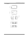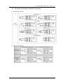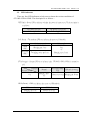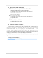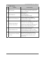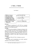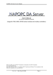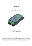
1
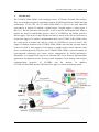
GT-540P-3GWA-OEM1 user’s manual v1.0 GT-540P-3GWA-OEM1 Intelligent 3G Remote Terminal Unit With GPS User’s Manual v1.0 High Quality, Industrial Data Acquisition, and Control Products 2013/03 Ver. 1.0 GT-540P-3GWA-OEM1 user’s manual v1.0 Warranty All products manufactured by ICP DAS are warranted against defective materials for a period of one year from the date of delivery to the original purchaser. Warning ICP DAS assumes no liability for damages consequent to the use of this product. ICP DAS reserves the right to change this manual at any time without notice. The information furnished by ICP DAS is believed to be accurate and reliable. However, no responsibility is assumed by ICP DAS for its use, or for any infringements of patents or other rights of third parties resulting from its use. Copyright Copyright 2010 by ICP DAS CO., LTD. All rights reserved worldwide. Trademark The names used for identification only may be registered trademarks of their respective companies. Version Version Date Author Description 1.0 2013/03/18 Alung Release version 2013/03 Ver. 1.0 GT-540P-3GWA-OEM1 user’s manual v1.0 Table of Contents 1. Introduction ............................................................................................... 2 1.1 1.2 1.3 1.4 Features............................................................................................................. 4 Software Architecture ....................................................................................... 4 Applications...................................................................................................... 7 How to use GT-540P-3GWA-OEM1................................................................ 9 2. Hardware ................................................................................................. 10 2.1 2.2 2.3 2.4 2.5 2.6 Specifications ................................................................................................. 10 Appearance and pin assignments.................................................................... 12 Dimensions ..................................................................................................... 13 DI/DO Internal Structure and Wire Connection ............................................. 14 LED indicators................................................................................................ 15 Installing GT-540P-3GWA-OEM1................................................................. 16 2.7 2.8 How to reset GT-540P-3GWA-OEM1............................................................ 17 Charge and discharge of Li-Battery................................................................ 17 3. Installing GT-540P-3GWA-OEM1 Utility .............................................. 18 3.1 3.2 Installing .NET Framework............................................................................ 18 Installing GT-540P-3GWA-OEM1 Utility ..................................................... 20 4. GT-540P-3GWA-OEM1 Utility Operation ............................................. 23 4.1 4.2 4.3 4.4 4.5 4.6 4.7 4.8 Main menu...................................................................................................... 24 Operation Language ....................................................................................... 26 Login............................................................................................................... 27 Main Parameters ............................................................................................. 30 Device Status .................................................................................................. 43 Device Time.................................................................................................... 44 Counter Value ................................................................................................. 45 DO control/DI status/AI value........................................................................ 47 4.9 4.10 4.11 GPRS/GSM Signal Quality ............................................................................ 48 Version ............................................................................................................ 49 System ............................................................................................................ 50 5. Data logger .............................................................................................. 52 5.1 5.2 5.3 The naming rule of logger file name .............................................................. 52 The data format of the data logger file ........................................................... 53 Delete Data Logger File Automatically.......................................................... 53 6. Trouble shooting...................................................................................... 54 GT-540P-3GWA-OEM1 user’s manual, Version 1.0, 2013/03 1/52 GT-540P-3GWA-OEM1 user’s manual v1.0 1. Introduction The GT-540P-3GWA-OEM1 is the intelligent Active 3G Remote Terminal Unit product. They are the highly integrated, stand-alone solution for M2M applications. Within the high performance 32 bit CPU, the GT-540P-3GWA-OEM1 is suit for the hard industrial environment. It features 3G module, 6 digital inputs, 2 digital outputs, 1 analog input, 2 RS-232, 1 RS-485 and micro SD interface. It can be used in M2M application fields to transfer the local I/O and Modbus device’s data via 3G/GPRS by the defined period or DI/AI triggers. The local I/O and GPS data can also be stored in the SD card to become a remote data logger. For another communication mode, the GT-540P-3GWA-OEM1 offers the e-mail mode to transfer the data by e-mail via 3G/GPRS for users to choose. The simple I/O linkage function of the GT-540P-3GWA-OEM1 can reach the real time control in the local field. It also supports Li-ion battery as another power source when the main power is failed temporarily. Therefore, the GT-540P-3GWA-OEM1 is an ideal solution for environmental monitoring and remote device management for M2M applications. Meanwhile, it is supplied with easy-to-use API and OPC server Software that streamline application development process, freeing system integrators from dealing with complex communication protocols of 3G/GPRS and the Internet. In addition, GT-540P-3GWA-OEM1 has the GPS function to apply in vehicle monitoring system. GT-540P-3GWA-OEM1 user’s manual, Version 1.0, 2013/03 2/52 GT-540P-3GWA-OEM1 user’s manual v1.0 z Easy to Establish 3G/GPRS Network Applications It is a big headache for engineers to establish the 3G/GPRS applications because the dynamic IP management is required. Applying the GT-540P-3GWA-OEM1 and M2M RTU center software, the dynamic IP addresses can be managed between them. The remote 3G/GPRS RTU product would connect to M2M RTU Center automatically. Therefore, all remote 3G/GPRS RTU devices can be managed by s single centralized M2M RTU Center software with a fixed IP address. Moreover, there are M2M API tool and OPC server for engineers to develop the 3G/GPRS applications by VB, VC or SCADA development tools conveniently without any IP address management effort. z Active data transmission The GT-540P-3GWA-OEM1 with active I/O transmission mechanism can raise the communication. Unlike the traditional poll communication, it would transfer the data by the defined time, DI trigger or AI hi/lo alarm. In addition to improve the way of communication, that can also reduce the AP effort. z Transfer data by e-mail Expect for the transferring data by the general communication with the M2M RTU center, users can choose the e-mail mode to send these data by e-mail over 3G/GPRS network in the fixed time. z Modbus RTU device connectivity The GT-540P-3GWA-OEM1 is built-in Modbus RTU protocol. That can make any Modbus RTU device connect to the GT-540P-3GWA-OEM1. By the way of GT-540P-3GWA-OEM1, Modbus RTU devices can be used in 3G/GPRS remote system. The max Modbus RTU device can be connected to the GT-540P-3GWA-OEM1 is three. z Simple Local I/O link Control There are I/O built-in 3G/GPRS RTU devices of ICP DAS. Therefore, these products can be the 3G/GPRS I/O devices. Expect for these local I/O data can be sent to the host PC, the I/O link function of them help users to do the simple control in local field. For example: the DI trigger or high/low AI alarm can driver the DO channel. z Built-in I/O Data Logging The GT-540P-3GWA-OEM1 provides an external mircro SD interface. These local I/O and Modbus data are recorded in SD memory card for one day in a single file. GT-540P-3GWA-OEM1 user’s manual, Version 1.0, 2013/03 3/52 GT-540P-3GWA-OEM1 user’s manual v1.0 1.1 Features z Automatic/continuous 3G/GPRS Link Management z Support Modbus RTU protocol to connect to Max 3 Modbus RTU devices via RS-485 port z Support M2M OPC server for SCADA system z Easy-to-use API tool for users to develop their applications by various program development tools z Can be the 3G/GPRS I/O devices z Support GPS function z Support data transferring by E-mail z Local I/O linkage function to make the simple local control z Support data logger in micro SD card (Max : 2 GB bytes) z Support 3.7V Li-ion Battery backup z Power supply 10 ~ 30 VDC 1.2 Software Architecture The M2M RTU center software with friendly Graphic interface is to manage the 3G/GPRS RTU products easily. Users can monitor the I/O data and status of 3G/GPRS RTU device by the interface on PC. By using the M2M RTU API tool and M2M RTU center software, any remote monitoring system can be achieved easily and efficiently. For SCADA system, the M2M.OPC server is provided to connect to SCADA by OPC interface. GT-540P-3GWA-OEM1 user’s manual, Version 1.0, 2013/03 4/52 GT-540P-3GWA-OEM1 user’s manual v1.0 M2M RTU management software- M2M RTU Center The M2M RTU Center provided by ICP DAS is a M2M (Machine to Machine) management software that has a strong core technology for handling data and lets the user save the trouble of dealing with large IO data. For detail information and downloading the software, please refer to: http://ftp.icpdas.com/pub/cd/usbcd/napdos/m2m/rtu/rtu_center GT-540P-3GWA-OEM1 user’s manual, Version 1.0, 2013/03 5/52 GT-540P-3GWA-OEM1 user’s manual v1.0 M2M RTU SDK- M2M RTU API ICP DAS M2M RTU Library is a software tool package for M2M RTU products. It provides the seamless connection with M2M RTU products (G-4500 RTU, GT-540P-3GWA-OEM1…) of ICP DAS for the user-designed system. With the APIs in this library, programmer can access M2M RTU devices by public software development environments, like VC, VB, BCB, visual studio.Net… It is easy to integrate these 3G/GPRS RTU devices to various applications including real the remote data, database management system. For detail information and downloading the software, please refer to: http://ftp.icpdas.com/pub/cd/usbcd/napdos/m2m/rtu/m2m_rtu_win32_api OPC server for RTU series of ICP DAS- NAPOPC.M2M DA Server ICP DAS NAPOPC.M2M DA Server is an OPC software package operated as an OPC driver of a HMI or SCADA system. It provides seamless connection with 3G/GPRS RTU products (G-4500 RTU, GT-540P-3GWA-OEM1…) from ICP DAS to SCADA system (InduSoft, Wonderware, iFix, Citec, LabView and etc) following OPC 1.0, OPC 2.0 Data Access Standards. For detail information and downloading the software, please refer to: http://ftp.icpdas.com/pub/cd/usbcd/napdos/m2m/rtu/napopc.m2m EzDatalogger EZ Data Logger is a small data logger software. It can be applied to small remote I/O system. With its user-friendly interface, users can quickly and easily build a data logger software without any programming skill. For the detail and downloaded from: http://www.icpdas.com/products/Software/ez_data_logger/ez_data_logger.html GT-540P-3GWA-OEM1 user’s manual, Version 1.0, 2013/03 6/52 GT-540P-3GWA-OEM1 user’s manual v1.0 1.3 Applications z Earthquake and Landslide Alarm system z Hydrologic monitoring System z Vending machine automation system z Sewage flow monitoring system z Piped water monitoring system z Vehicle monitoring system Vehicle monitoring System GT-540P-3GWA-OEM1 user’s manual, Version 1.0, 2013/03 7/52 GT-540P-3GWA-OEM1 user’s manual v1.0 Hydrologic monitoring System GT-540P-3GWA-OEM1 user’s manual, Version 1.0, 2013/03 8/52 GT-540P-3GWA-OEM1 user’s manual v1.0 1.4 How to use GT-540P-3GWA-OEM1 GT-540P-3GWA-OEM1 user’s manual, Version 1.0, 2013/03 9/52 GT-540P-3GWA-OEM1 user’s manual v1.0 2. Hardware 2.1 Specifications GT-540P-3GWA-OEM1 System CPU 32 bit CPU SRAM 64 KB Flash Memory 512 KB RTC Gives time(sec, min, hour) & date, leap year compensation Watchdog Yes Micro SD Inerface Max 2GB Serial ports COM1 RS-232 : TXD,RXD,GND for configuration RS-485:D+,D- for Modbus RTU device connectivity COM2 Digital Input Channels 6 Input Type Sink or Source, Isolated channel with common power or ground Off Voltage Level +1V max. On Voltage Level +3.5 ~ 30 VDC Isolated Voltage 3750Vrms Counters 6 (16 Bit, 5~40Hz), Min. Pulse Width : 25ms Digital Output Channels 2 Output Type Open-Collector (NPN) (100mA@30VDC) Load Voltage +30 V max Load Current 100 mA max Isolated Voltage 3750Vrms Analog Input Channels 1 Resolution 12 bit Input Range/Type 0 ~ 20 mA 2G System GPRS Quad-band 850/900/1800/1900 MHz GPRS multi-slot : class 10/8 GPRS mobile station : class B GPRS class 10 : Max download speed 85.6 kbps Compliant to GSM phase 2/2+ -Class 4(2W @ 900 MHz) GT-540P-3GWA-OEM1 user’s manual, Version 1.0, 2013/03 10/52 GT-540P-3GWA-OEM1 user’s manual v1.0 -Class 1(1W @ 1800/1900 MHz) Coding schemes : CS 1, CS 2,CS 3,CS 4 3G System Frequency Band 850/900/1900/2100 MHz Data Transmission Downlink transfer: 7.2Mbps (HSDPA) Uplink transfer: 5.76Mbps (HSUPA) Power class Class 3(250mW @ WCDMA/HSPA) GPS Interface Support Channels 32 Sensitivity Tracking = up to -159 dBm (with external LNA) Cold start = up to -146 dBm (with external LNA) Acquisition Time Hot start (Open Sky) = 2 s(typical) Cold start (Open Sky) = 36 s(typical) Protocol Support GPRSC format (NMEA 0183 version 3.01) Power Protection Reverse polarity protection Frame Ground Protection ESD, Surge, EFT, Hi-Pot Required Supply Voltage +10 VDC ~ +30 VDC Mechanical Casing Plastic Flammability UL 94V-0 materials Dimensions (W x H x D) 91 mm x 132 mm x 52 mm Installation DIN-Rail Environment Operating Temperature -25 °C ~ +75 °C Storage Temperature -40 °C ~ +80 °C Humidity 5 ~ 95% RH, non-condensing GT-540P-3GWA-OEM1 user’s manual, Version 1.0, 2013/03 11/52 GT-540P-3GWA-OEM1 user’s manual v1.0 2.2 Appearance and pin assignments The GT-540P-3GWA-OEM1 is with the GPS antenna connector and LEDs. The following figure shows the appearance of GT-540P-3GWA-OEM1. DI/DO Terminal No. DI DI COM DO PWR DO DO GND N/A Ain+ Ain- Pin Assignment 01 02 03 04 05 06 07 08 09 10 11 12 13 14 DI0 DI1 DI2 DI3 DI4 DI5 DI COM DO PWR DO0 DO1 DO GND N/A Ain+ Ain- COM Port & Power Input Terminal No. Ground for COM COM1 RS-232 COM2 RS-485 Reset Power Input: +10 ~ 30VDC Frame Ground Pin Assignment 01 02 03 04 05 06 07 GND RxD1 TxD1 D+ DRST+ RST- 08 09 10 DC.+VS DC.GND F.G GT-540P-3GWA-OEM1 user’s manual, Version 1.0, 2013/03 12/52 GT-540P-3GWA-OEM1 user’s manual v1.0 2.3 Dimensions GT-540P-3GWA-OEM1 user’s manual, Version 1.0, 2013/03 13/52 GT-540P-3GWA-OEM1 user’s manual v1.0 2.4 DI/DO Internal Structure and Wire Connection (1) DI Internal Structure (2) DI Internal Structure GT-540P-3GWA-OEM1 user’s manual, Version 1.0, 2013/03 14/52 GT-540P-3GWA-OEM1 user’s manual v1.0 2.5 LED indicators There are four LED indicators to help users to know the various conditions of GT-540P-3GWA-OEM1. The description is as follows: EXT(Red):Power LED to indicate whether the power is input or not. The description is as follows: The power is active The power is not active on off 3G (Green):The modem LED can indicate the status of 3G module. Modem normal Modem fail GPRS Mode Blanking per 3 sec WCDMA Mode Twinkling twice per 3 sec Off or Blanking (not 3 sec) STA(Orange):System LED is to indicate if the GT-540P-3GWA-OEM1 is normal or fail. Condition External power Normal On Blanking per 1 sec WCDMA/GPRS Fail PIN code is wrong Always on or off Blinking per 50 ms GPS (Green):GPS can indicate the status of GPS module GPS normal Blinking per 1 sec GPS fail Always on or off GT-540P-3GWA-OEM1 user’s manual, Version 1.0, 2013/03 15/52 GT-540P-3GWA-OEM1 user’s manual v1.0 2.6 Installing GT-540P-3GWA-OEM1 It needs to follow these steps to install the GT-540P-3GWA-OEM1 below: 1. Install the 3G/GPRS antenna. GT-540P-3GWA-OEM1 must install GPS antenna additionally. 2. Plug in the normal SIM card (Before apply the SIM card, confirm it is OK by the mobile phone.) 3. Pin08 and Pin09 connect to the DC.+VS and DC.GND of the power supply. 4. Follow the section 2.4 to wire the I/O connection. 5. If you want to use the backup power, please connect the Li-battery to the GT-540P-3GWA-OEM1. 6. It is needed to wait for 30 ~ 50 seconds to search the GSM base and register to the ISP. After finishing the process, GT-540P-3GWA-OEM1 would be in normal operation mode and the STA LED would blank per 3 sec. The start time of GT-540P-3GWA-OEM1 depends on the strength of signal. GT-540P-3GWA-OEM1 user’s manual, Version 1.0, 2013/03 16/52 GT-540P-3GWA-OEM1 user’s manual v1.0 2.7 How to reset GT-540P-3GWA-OEM1 The Li-Battery has been applied in GT-540P-3GWA-OEM1 1. Remove Li-Battery from GT-540P-3GWA-OEM1. 2. Turn off the external power and confirm the EXT LED is off. 3. Turn on the external power. 4. Re-install the Li-Battery. The Li-Battery is not applied 1. Turn off the external power and confirm the EXT LED is off. 2. Turn on the power. Reset Pins 1. Connect CON1.6 to DC.+VS 2. Connect CON1.7 to DC.GND 2.8 Charge and discharge of Li-Battery If users apply the Li-Battery on GT-540P-3GWA-OEM1, the Li-battery would be charged by the external power automatically. When the external power is removed from GT-540P-3GWA-OEM1, the power supplying to GT-540P-3GWA-OEM1 is from Li-Battery. When the power is only from Li-Battery, the running time of the GT-540P-3GWA-OEM1 is depended on the frequency of transmission and the volume of Li-battery. We suggest users to exchange the Li-Battery every 6 months. ICP DAS provides 600 mAh and 1200 mAh Li-batteries for users to pick out and buy. Li-Battery ordering information BT1200 3.7V 1200 mAh Battery GT-540P-3GWA-OEM1 user’s manual, Version 1.0, 2013/03 17/52 GT-540P-3GWA-OEM1 user’s manual v1.0 3. Installing GT-540P-3GWA-OEM1 Utility It needs the runtime environment with .NET Framework 2.0 or above to execute the GT-540P-3GWA-OEM1 Utility in the PC. If there has .NET Framework 2.0 or above in the PC, the section 3.1 can be omitted. 3.1 Installing .NET Framework Please download the .NET Framework 2.0 on the Microsoft web site and install it. The install figure is as follows: (1) Press “Next" to the next step. (2) Select the “I accept the terms of the License Agreement" and “Install "to the next step. GT-540P-3GWA-OEM1 user’s manual, Version 1.0, 2013/03 18/52 GT-540P-3GWA-OEM1 user’s manual v1.0 (3) The installation process would be going (4) After finishing the installation, press “Finish" to exit the program. GT-540P-3GWA-OEM1 user’s manual, Version 1.0, 2013/03 19/52 GT-540P-3GWA-OEM1 user’s manual v1.0 3.2 Installing GT-540P-3GWA-OEM1 Utility Launch “Install_GT540_Utility_Vxxx.exe”(xxx:Version Number) and the installation figure is as follows: (1) Press “Next" to start the installation procedure. (2) Select the installation path. The default path is "C:\Progrm Files\GT-540P-3GWA-OEM1 Utility". Press “Next" to the next step. GT-540P-3GWA-OEM1 user’s manual, Version 1.0, 2013/03 20/52 GT-540P-3GWA-OEM1 user’s manual v1.0 (3) Input the name shown in “All Programs". Press “Next" to the next step. (4) After finishing the installation procedure, press “OK" to the next step GT-540P-3GWA-OEM1 user’s manual, Version 1.0, 2013/03 21/52 GT-540P-3GWA-OEM1 user’s manual v1.0 (5) Press "Finish" to finish the installation procedure. (6) Launch GT-540P-3GWA-OEM1 Utility from the start menu "StartÆAll ProgramsÆGT-540 UtilityÆGT-540P-3GWA-OEM1 Utility". GT-540P-3GWA-OEM1 user’s manual, Version 1.0, 2013/03 22/52 GT-540P-3GWA-OEM1 user’s manual v1.0 4. GT-540P-3GWA-OEM1 Utility Operation Before GT-540P-3GWA-OEM1 utility is connected to the PC correctly, please confirm these following steps: 1. The STA LED is blanking. There are 2 kinds of blanking in GT-540P-3GWA-OEM1. STA LED Description Blanking per 1 sec Normal mode Blanking per 50 ms The pin code is wrong. The login windows would show the field to input pin or PUK code 2. Confirm the RS232 connection between GT-540P-3GWA-OEM1 and PC is correct. Users can refer to the following figure. 3. During the setting procedure, the power must be on. GT-540P-3GWA-OEM1 user’s manual, Version 1.0, 2013/03 23/52 GT-540P-3GWA-OEM1 user’s manual v1.0 4.1 Main menu The main menu of GT-540P-3GWA-OEM1 Utility includes the following sections: 1. Tool Menu (1) “COM”: Set the COM port number in PC connecting to GT-540P-3GWA-OEM1. (2) Login/Logout Before operating GT-540P-3GWA-OEM1, users need to login to GT-540P-3GWA-OEM1 Utility. After login the system successfully, the menu item “login” would become “logout” and the GT-540P-3GWA-OEM1 Utility would be operated normally. Once the power is reset, the login procedure needs to do again. (3) “Language” GT-540P-3GWA-OEM1 Utility only supports English interface. (4) File There are import and export functions in “File” item. The functions would be enabled when “Main parameters” window is open. Export : The function can export the parameters to the defined .par file from the “Main parameters” windows. Import : The parameters would be shown in “Main parameters” window from the defined .par file. (5) Version: Including the firmware and Utility version information. GT-540P-3GWA-OEM1 user’s manual, Version 1.0, 2013/03 24/52 GT-540P-3GWA-OEM1 user’s manual v1.0 (6) System : Provide users for recovering GT-540P-3GWA-OEM1 to factory, resetting GT-540P-3GWA-OEM1 and debug mode. (7) Exit: To exit GT-540P-3GWA-OEM1 utility 2. Function Item: (1) “Main parameter”: The main parameter setting of GT-540P-3GWA-OEM1 includes ID, SIM number, operation mode, data logger period and GPS item. (2) Device Status: Display these peripheral devices status including microSD, 3G/GPRS, GPS and Modbus RTU. (3) “Device time”: Display or set the RTC time of GT-540P-3GWA-OEM1 in this item. It is also can get the information of the last and next time of the return report in E-mail mode. (4) “DO Control and DI/AI status”: Display the status of I/O and control the DO output. (5) “Counter Value”: Inquire and set the counter value. (6) Version: Inquire the versions of Firmware and Utility. 3. Status Line Show the related information during the operation procedure including: (1) The com port number of PC (2) The communication setting of COM Port (3) The status of COM Port (4) The result of Utility operation GT-540P-3GWA-OEM1 user’s manual, Version 1.0, 2013/03 25/52 GT-540P-3GWA-OEM1 user’s manual v1.0 4.2 Operation Language GT-540P-3GWA-OEM1 Utility only supports English version currently. In the future, the Traditional Chinese and Simplified Chinese will be supported from the “language” menu bar. GT-540P-3GWA-OEM1 user’s manual, Version 1.0, 2013/03 26/52 GT-540P-3GWA-OEM1 user’s manual v1.0 4.3 Login It needs to login to GT-540P-3GWA-OEM1 to set its parameters. The description is below: (1) Select the COM port number of PC. (2) Press the “login” button. (3) If you are the first time to login, please set the system time of GT-540P-3GWA-OEM1. If the pin code in GT-540P-3GWA-OEM1 is not correct, the STA led would be blanking per 50 ms and GT-540P-3GWA-OEM1 utility would ask for users to input Pin or PUK code. (1) Asking for inputting PIN code: If the PIN code is effective, the “Enter SIM PIN/SIM PUK” window would pop-up as follows. If the number of times for inputting the wrong PIN code is more than the allowed number, the PIN code would be ineffective. And the “PUK code” window would pop up. GT-540P-3GWA-OEM1 user’s manual, Version 1.0, 2013/03 27/52 GT-540P-3GWA-OEM1 user’s manual v1.0 GT-540P-3GWA-OEM1 user’s manual, Version 1.0, 2013/03 28/52 GT-540P-3GWA-OEM1 user’s manual v1.0 (2) Asking for inputting PUK code If the PIN code is ineffective, the “PUK code" window would pop-up as follows. As the number of times for inputting the wrong PUK code is more than allowed number, the SIM card would be ineffective forever. Therefore, it is important to input the correct PUK code. If the PIN or PUK code is correct, the STA led would blank per second. Users can operate other function of GT-540P-3GWA-OEM1 in this utility. GT-540P-3GWA-OEM1 user’s manual, Version 1.0, 2013/03 29/52 GT-540P-3GWA-OEM1 user’s manual v1.0 4.4 Main Parameters There are four group in the left side of the ”Main Parameters” window. They are Main Info, DI Info, AI Info and Modbus Device groups. Users can inquire or set these parameters of these groups in the right side. 4.4.1 Main Info (1) System Info Item Description Machine Name Device Name. This name would be shown in the E-Mail mode. (Range : 1~20 characters) SIM Card Number This text field can show or input the phone number of the plug-in SIM card. (Range : 0~20 characters) Mode Operation mode: 1. RTU mode- In this mode, GT-540P-3GWA-OEM1 would transfer I/O data (local I/O, Modbus device and GPS data) to the M2M RTU center by 3G/GPRS connection periodically. 2. E-Mail mode: Transfer I/O data by the e-mail attached file through 3G/GPRS connection periodically. Data Logger Period(sec) This time is used for recording I/O data to I/O logger files periodically by second unit. If the value is 0, this I/O data logger function is disabled. (Range : 0~65535 sec) Enable GPS Enable: Enable the GPS function. Disable: Disable the GPS function (2) GPRS Info GT-540P-3GWA-OEM1 user’s manual, Version 1.0, 2013/03 30/52 GT-540P-3GWA-OEM1 user’s manual v1.0 Item Description GPRS APN The setting is important factor when connecting to a GPRS network. Check with your GPRS service provider for details. Access point name (APN) is the name used to identify a general packet radio service (GPRS) bearer service in the GSM mobile network. The APN defines the type of service that is provided in the packet data connection. You can get this APN by ISP. (Range : 0~31 Characters) GPRS User Name The setting is important factor when connecting to a GPRS network. Check with your GPRS service provider for details. (Range : 0~31 Characters) GPRS User Password The setting is important factor when connecting to a GPRS network. Check with your GPRS service provider for details. (Range : 0~31 Characters) (3) RTU Mode GT-540P-3GWA-OEM1 user’s manual, Version 1.0, 2013/03 31/52 GT-540P-3GWA-OEM1 user’s manual v1.0 Item Description Machine ID The device Station ID would be shown in the RTU Center software. It can identify the different GT-540P-3GWA-OEM1 device in the Remote OPC Server. (Range: 1 ~ 65535) Data Update Period(sec) Set the report time interval. The GT-540P-3GWA-OEM1 would send the data to M2M RTU Center periodically depending on this update time. The based unit is second. (Range: 0 ~ 999999 sec) Heartbeat Period(sec) Set the heartbeat time interval. When the GT-540P-3GWA-OEM1 update time is too long to terminate the GPRS connection by ISP, the heartbeat time will report smaller package to keep GPRS connection. (unit: sec) (Range: 0 ~ 999999 sec) Note: Some ISP companies would terminate the GPRS connection when the GPRS connection has any data flow for some time. (4) Server Info Item Description Server Domain Name The server domain name. In RTU mode, it indicates the PC running M2M RTU Center. In E-mail mode, it indicates the E-mail server. (Range : 0 ~ 31 Characters) GT-540P-3GWA-OEM1 user’s manual, Version 1.0, 2013/03 32/52 GT-540P-3GWA-OEM1 user’s manual v1.0 Server IP The IP address of the server In RTU mode, it indicates the PC running M2M RTU Center. In E-mail mode, it indicates the E-mail server. Server Port The port of the server is used for GT-540P-3GWA-OEM1 connecting to. In RTU mode, the port is 10000. In E-mail mode, the port is 25. (Ranged : 0~65535) Primary DNS The primary Domain name server IP Second DNS The secondary Domain name server IP (5) E-mail Mode Item Description E-mail Authority The GT-540P-3GWA-OEM1 only support two way of authority to login e-mail server 1. none: No authority 2. auth-long: AUTH-LONG Server User Name The user name to login to the e-mail server (Range : 0 ~ 35 characters) Server Password The password to login to the e-mail server (Range : 0 ~ 35 characters) E-mail Subject The subject of the e-mail (Range : 0 ~ 128 characters) E-mail From The sender of the e-mail. This field dose not allow the empty string in E-mail mode (Range : 1 ~ 51 characters) Max. size of one E-mail file (KB) The maximum size of the e-mail. The suggestion size is 1300 KBytes GT-540P-3GWA-OEM1 user’s manual, Version 1.0, 2013/03 33/52 GT-540P-3GWA-OEM1 user’s manual v1.0 (Range : 110 ~ 2500 KB) Max. size of one attached file (KB) The maximum size of the attached files in a e-mail. The suggestion size is 600 KBytes (Range : 100 ~ 1200 KB) Report Period(min) The interval time to send the e-mail. (Range : 0~65535 min) Report Base Time(hour) The first time of hour to send the e-mail (Range : 0~23 hour) Report Base Time(min) The first time of minute to send the e-mail (Range : 0~59 minute) (6) Receiver Address Item Description E-mail Addr. 1~ E-mail Addr. 10 In E-Mal mode, users can set the e-mail addresses of receivers in these fields. (Range : 0 ~ 51 Characters) (7) RS-485 Info GT-540P-3GWA-OEM1 user’s manual, Version 1.0, 2013/03 34/52 GT-540P-3GWA-OEM1 user’s manual v1.0 Item Description Baudrate The baud rate of the COM2 (RS-485) Data Bit The data bit of the COM2 Stop Bit The stop bit of the COM2 Parity Bit The parity bit of the COM2 (none, odd, even) 4.4.2 (1) DI/DO Info DI Item Description Type The function is used to set the type of DI channel: 1. Disable : Disable the linkage function between DI and DO channels. 2. DI NO : The DI channel is normal Open. When the DI channel is close (high), it is the trigger signal of GT-540P-3GWA-OEM1. 3. DI NC:The DI channel is normal close. When the DI channel is open (low), it is the trigger signal in the system. 4. DI Counter: Set the DI channel as counter mode. Triggered Hold Time(sec) This value represents the holding time of the DI signal for triggering the event. The unit is second. (Range : 0 ~ 65535 sec) Return Hold Time(sec) When the trigger condition is activated, it needs to keep the non-trigger status to be triggered again according to the“Return GT-540P-3GWA-OEM1 user’s manual, Version 1.0, 2013/03 35/52 GT-540P-3GWA-OEM1 user’s manual v1.0 Hold Time". The unit is second. (Range : 0 ~ 65535 sec) DO Channel The text will define which DO channel will output according to the DI triggering. (Channel 0 ~ 1) DO On Time(sec) The DO channel would keep outputting according to this time, when DI channel is triggered and “DO Off Condition” is “time”. The unit is second. (Range : 0 ~ 65535 sec) DO Off Condition These conditions of the DO terminating outputting when DO is output by DI trigger. 1.Disable: Disable the DO linkage with DI channel. 2.Time: The DO output would keeping “ON” according to the “DO on Time” when DI is triggered. 3.Input Status: The DO channel output would be kept contiguously according to the time of the “Return Hold Time” when the DI returns to the non-trigger status (2) DO Item Description Cycle Time(sec) The time of a duty cycle for DO. If it is 0, duty cycle function is disabled. (Range : 0 ~ 65535 , Unit : Second) Cycle Percent(%) The percentage of DO output would keeping “ON” in a duty cycle. (Range : 0 ~ 100, Unit : %) Auto-Stop Time(sec) If the GT-540P-3GWA-OEM1 disconnect to RTU Center over this time, the operation of duty cycle would be stopped automatically. If it is 0, the GT-540P-3GWA-OEM1 does not stop the operation of duty cycle automatically. (Range : 0 ~ 65535 , Unit : Second) GT-540P-3GWA-OEM1 user’s manual, Version 1.0, 2013/03 36/52 GT-540P-3GWA-OEM1 user’s manual v1.0 4.4.3 AI Info Item Description Condition 1 There are three modes of the AI triggers in this condition. 1.Disable : Disable the DO linkage 2.High Alarm : The DO is activated when the AI exceeds the alarm value. 3.Low Alarm : The DO is activated when the AI is lower than the alarm value. Alarm Value The alarm value of AI channel (Range : 0 ~ 20 mA) Triggered Hold Time(sec) This value represents the holding time of the AI signal for triggering the event. The unit is second. (Range : 0 ~ 65535 sec) Return Hold Time(sec) When the trigger condition is activated, it needs to keep the non-trigger status to be triggered again according to the “Return Hold Time". The unit is second. (Range : 0 ~ 65535 sec) DO Channel The DO channel will be activated according to the AI alarm. (Channel 0 ~ 1) DO On Time(sec) The DO channel would keep outputting by this time, when AI alarm is triggered and “DO Off Condition" is “time". The unit is second. (Range : 0 ~ 65535 sec) DO Off Condition These conditions of the DO terminating GT-540P-3GWA-OEM1 user’s manual, Version 1.0, 2013/03 37/52 GT-540P-3GWA-OEM1 user’s manual v1.0 outputting when DO is output by AI trigger. 1. Disable: Disable the DO linkage with AI channel. 2. Time: The DO output would keeping outputting according to the “DO on Time” when AI alarm is triggered. 3. Input Status: The DO channel output would be kept contiguously according to the time of the “Return Hold Time” when the AI returns to the non-trigger status Condition 2 The second condition of AI trigger. The trigger modes are as condition 1. Alarm Value The alarm value of AI channel (Range : 0 ~ 20 mA) Triggered Hold Time(sec) This value represents the holding time of the AI signal for triggering the event. The unit is second. (Range : 0 ~ 65535 sec) Return Hold Time(sec) When the trigger condition is activated, it needs to keep the non-trigger status to be triggered again according to the “Return Hold Time". The unit is second. (Range : 0 ~ 65535 sec) DO Channel The DO channel will be activated according to the AI alarm. (Channel 0 ~ 1) DO On Time(sec) The DO channel would keep outputting by this time, when AI alarm is triggered and “DO Off Condition" is “time". The unit is second. (Range : 0 ~ 65535 sec) DO Off Condition These conditions of the DO terminating outputting when DO is output by AI trigger. 1. Disable: Disable the DO linkage with AI channel. 2. Time: The DO output would keeping outputting according to the “DO on Time” when AI alarm is triggered. 3. Input Status: The DO channel output would GT-540P-3GWA-OEM1 user’s manual, Version 1.0, 2013/03 38/52 GT-540P-3GWA-OEM1 user’s manual v1.0 be kept according to the time of the “Return Hold Time” when the AI returns to the non-trigger status The Conditions of AI Trigger GT-540P-3GWA-OEM1 user’s manual, Version 1.0, 2013/03 39/52 GT-540P-3GWA-OEM1 user’s manual v1.0 4.4.4 Modbus Device The GT-540P-3GWA-OEM1 is allowed to connect to three Modbus RTU devices. Therefore, users can get these data of Modbus devices form the remote site by applying the GT-540P-3GWA-OEM1. The section is shown how to set the settings to connect to the Modbus devices. 1. Adding a Modbus device in the GT-540P-3GWA-OEM1 Utility Following these steps to add a Modbus device to the GT-540P-3GWA-OEM1 (1) Select ”Modbus Device” in the left window and press the right button of the mouse as the following figure. (2) Select ”Add Device” to add a Modbus device. (3) There are Modbus device of ICP DAS for users to select. If the Modbus device connected to GT-540P-3GWA-OEM1 is not in the list, please select “Customer" item to add this Modbus device. 2. Remove a Modbus RTU device Follow these steps to remove a Modbus device from the GT-540P-3GWA-OEM1. (1) Select the Modbus device that you want to remove and click the right button of the mouse. (2) Select ”Delete Device” to remove this Modbus device GT-540P-3GWA-OEM1 user’s manual, Version 1.0, 2013/03 40/52 GT-540P-3GWA-OEM1 user’s manual v1.0 3. Description of parameters Item Description Device name The name of the Modbus RTU device Device Address The ID of the Modbus RTU device DI Channels The number of DI channel DI Address The start address of reading the DI value DO Channels The number of DO channels DO Address The start address of reading the DO value AI Channels The number of AI channel AI Address The start address of reading the AI value AI Format The format of AI value. Custom modbus device only support 16 bits value. AI Type AI type AO Channels The number of AO channels AO Address The start address of reading the AO value AO Format The format of AO value. Custom modbus device only support 16 bits value. AO Type AO type GT-540P-3GWA-OEM1 user’s manual, Version 1.0, 2013/03 41/52 GT-540P-3GWA-OEM1 user’s manual v1.0 4.4.5 Import/Export Parameters There are Import Parameters and Export Parameters in the list as the figure. These functions would be enabled as “Main Parameters” window is open. 1. Import Parameters: This function would read these parameters from *.par and show in “Main Parameters” window. When pressing ”Import Parameters” button, the following window would pop-up. Select the path and the file to finish the importing process. 2. Export Parameters: This function would export these parameters to the *.par file. When pressing ”Export Parameters” button, the following window would pop-up. After selecting the path and set the file name, press “SAVE” button to finish the process. GT-540P-3GWA-OEM1 user’s manual, Version 1.0, 2013/03 42/52 GT-540P-3GWA-OEM1 user’s manual v1.0 4.5 Device Status The window would show the status of micro SD card, WCDMA/GPRS connection, GPS and the Modbus devices connected to the GT-540P-3GWA-OEM1. Operation description: Read: Pressing this button would update the status of the GT-540P-3GWA-OEM1. Field instruction: (1) SD Card 1. Status: Shows the status of micro SD card. (OK- normal Error- abnormal) 2. Free Size (Byte): The remainder space of SD card (2) GPRS 1. Status: Shows the status of GPRS connection. 2. Error Code: This code is for the connection status. (3) GPS 1. Status: Shows the GPS function is enable or disable. 2. Data: The current $GPRMC data of GPS (4) M-7016/M-7060/M7080B This field shows the status of Modbus device connected to the GT-540P-3GWA-OEM1. 1. Address:Modbus RTU address 2. Status: The connection status between the GT-540P-3GWA-OEM1 and Modbus RTU device 3. Status Code: The code is for the connection status. GT-540P-3GWA-OEM1 user’s manual, Version 1.0, 2013/03 43/52 GT-540P-3GWA-OEM1 user’s manual v1.0 4.6 Device Time This window provides the function to inquire or modify the time of GT-540P-3GWA-OEM1. Besides, in the E-Mail mode, the next and last report times are also shown in the window. The text field operation is below. Field instruction: (1) Device Time: Show or set the time of GT-540P-3GWA-OEM1. (2) E-Mail Report Time: This field show the next time to send the mail when mail mode is enabled. If the time is changed, the information would be updated. (3) Last E-Mail Report Time: This field show the last time to send the mail when the mail mode is enabled. Operation description: (1) Set as Now: Set the time of the GT-540P-3GWA-OEM1 according to the time of PC. (2) Set: Set the time of the GT-540P-3GWA-OEM1 according to the time of the field. (3) Read: This button would read the GT-540P-3GWA-OEM1 time, the next time of sending the mail and the last time of sending mail. GT-540P-3GWA-OEM1 user’s manual, Version 1.0, 2013/03 44/52 GT-540P-3GWA-OEM1 user’s manual v1.0 4.7 Counter Value This window provides the function to inquire and modify the counter values of DI0 ~ DI5. The explanation of operation and text field is below: Text field: (1) Name: The DI name of DI0 ~ DI5。 (2) Value:The current counter value ( maximum: 999999999) (3) Set Value: Input the defined counter value. The maximum is 999999999. This field is enabled when DI is set as counter mode. (If users want to clear these counter values, set 0 to these counter values.) Operation: (1) Read: Read the current counter value and alarm settings from GT-540P-3GWA-OEM1. If the DI channel is not set as counter, the counter value is 0. (2) Set Value : Change the counter value into GT-540P-3GWA-OEM1 according to the "Set Value" field When the DI channels are set as counter and data logger is enabled, the CIx field would be added in csv files as the figure below. (x: the number of DI channel) GT-540P-3GWA-OEM1 user’s manual, Version 1.0, 2013/03 45/52 GT-540P-3GWA-OEM1 user’s manual v1.0 GT-540P-3GWA-OEM1 user’s manual, Version 1.0, 2013/03 46/52 GT-540P-3GWA-OEM1 user’s manual v1.0 4.8 DO control/DI status/AI value This function is used to control DO0 and DO1 channels and show the status of DI channels and AI value. Text field: (1) DI0 ~ DI5、DO0 ~ DO1: Gray: the voltage logic is high. Red: the voltage logic is low (2) AI Value : the AI current value (3) Gain : Gain value. It can calibrate the AI value (4) Offset : Offset value. It can calibrate the AI value Operation: (1) Read : Read back the status of DI/DO (2) (3) (4) (5) and AI value from GT-540P-3GWA-OEM1. DO0 ~ DO1 ON:Set the DO output on DO0 ~ DO1 OFF:Set the DO output off Duty Cycle “START” : Start the operation of Duty cycle Duty Cycle “STOP” : Stop the operation of Duty cycle GT-540P-3GWA-OEM1 user’s manual, Version 1.0, 2013/03 47/52 GT-540P-3GWA-OEM1 user’s manual v1.0 4.9 GPRS/GSM Signal Quality This window can show GSM signal strength. Text field: The strength is divided into 5 sections shown in percentage. And the top-left corner of the window can show the signal type. Operation: (1) Read:Read the WCDMA/GPRS signal strength. GT-540P-3GWA-OEM1 user’s manual, Version 1.0, 2013/03 48/52 GT-540P-3GWA-OEM1 user’s manual v1.0 4.10 Version Press "Version" in tool menu, and the window would show the version of Utility and firmware. Text field: (1) Firmware version: show the version information of GT-540P-3GWA-OEM1’s firmware (2) Utility version: show the version information of GT-540P-3GWA-OEM1’s utility Operation: Read: Read these information from GT-540P-3GWA-OEM1. GT-540P-3GWA-OEM1 user’s manual, Version 1.0, 2013/03 49/52 GT-540P-3GWA-OEM1 user’s manual v1.0 4.11 System “System” menu item has 3 functions. They are recovering factory setting, resetting and debug mode GT-540P-3GWA-OEM1 as the figure below. 4.11.1 Recover to Factory Settings The function is used to recover GT-540P-3GWA-OEM1 as factory settings including password. (1) Make sure the STA led is blanking per 1 sec. (2) Select the Recover to Factory Settings. 4.11.2 Reset GT-540P-3GWA-OEM1 The function is used to reset GT-540P-3GWA-OEM1 by software. (1) Make sure STA led is blanking per 1 second (2) Select “Reset GT-540” button to reset GT-540P-3GWA-OEM1. 4.11.3 Debug In this Debug mode, users can test mail function and show debug messages. The test or debug messages could be saved as the file. GT-540P-3GWA-OEM1 user’s manual, Version 1.0, 2013/03 50/52 GT-540P-3GWA-OEM1 user’s manual v1.0 Operation: (1) Mail Test: In the E-mail mode, click the button to send the E-mail to the defined e-mail address. (2) Monitor: This function can transfer the debug messages from GT-540P-3GWA-OEM1 and show in the Window. (3) Save message: Save the debug messages as files. (4) Clear: Clear the information in the debug filed. GT-540P-3GWA-OEM1 user’s manual, Version 1.0, 2013/03 51/52 GT-540P-3GWA-OEM1 user’s manual v1.0 5. Data logger The data logger would be enabled as the “Data Logger Period" is not 0. The logger files would be saved as csv file in SD card. The different modes provide the different file path, but the same file name and data format. (1) RTU mode: The current file is stored in the path of RUNTIME. The system would store the data to the new file at the time 00: 00 every day and copy the old file to the path of LOGFILE. In this mode, the timing of changing file name is as follows: 1. At 24 o'clock every day 2. Change Modbus RTU device connected to GT-540P-3GWA-OEM1. 3. Change the interval time of record. 4. Change DI type as counter 5. Disable/Enable GPS (2) E-Mail mode: The current file of data logger is stored in the path of RUNTIME. As arriving the time to send e-mail, the system would move the file to the path of UPLOAD and package the file as e-mail file in the path of EMAIL. The logger file would be stored in the path of LOGFILE. When finishing sending E-mail, the E-mail file would be deleted. In this mode, the timing of changing file name is as follows: 1. The logger file is over the setting of ”Max. size of one attached file”. 2. The upload time is arrived. 3. Change Modbus RTU device connected to GT-540P-3GWA-OEM1. 4. Change the interval time of record. 5. Change DI type as counter 6. Disable/Enable GPS 5.1 The naming rule of logger file name The file of I/O data logger is csv type. The naming rule is according to the time of creating file. The description is as follows. yyyymmdd_HHMMSS_Period.csv yyyy : year mm : month dd : day GT-540P-3GWA-OEM1 user’s manual, Version 1.0, 2013/03 52/52 GT-540P-3GWA-OEM1 user’s manual v1.0 HH : hour(24h) MM : minute SS : second Period : Data Logger Period 5.2 The data format of the data logger file The content of the file apply comma char to separate the different field. The first row data is the name of the fields. After the first row data, it is I/O data. The format of I/O data is date, time, local I/O, Modbus data and GPS data. The max number of Modbus device is three. Users can refer the following complete example to understand that. CI0 CI1 DI2 DI3 DI4 DI5 DO0 DO1 AI0 Module [M-7016] Addr. DI0 DO0 Date 20100520 175518 119 230 0 1 1 0 0 0 0.059 5 1 0 20100520 175519 119 230 0 1 1 0 0 0 0.058 5 1 0 DO1 DO2 DO3 AI0 AI1 AO0 Module [M-7060] Addr. DI0 DI1 DI2 DI3 DO0 0 0 0 0.033 0.671 1.500 5 1 0 0 0 1 0 0 0 0.034 0.671 1.500 5 1 0 0 0 1 DO1 DO2 DO3 Module [M-7080B] Addr. DO0 DO1 CI0 CI1 0 0 0 1 0 0 655361 5961 0 0 0 1 0 0 655361 5961 5.3 Delete Data Logger File Automatically At 24 o’clock every day , the GT-540P-3GWA-OEM1 would check the free space of micro SD card, if the free space of the micro SD card has less than 50MB, it would delete the oldest data logger files in the path of LOGFILE automatically until the free space has larger than 50MB. GT-540P-3GWA-OEM1 user’s manual, Version 1.0, 2013/03 53/52 GT-540P-3GWA-OEM1 user’s manual v1.0 6. Trouble shooting Item 1 2 3 Condition Trouble shooting EXT Led is off. The external power has problem. Please check the wire is connected correctly and the power voltage is 10~30VDC. STA is always on. Check SIM card Check GSM Antenna Check the GSM signal strength GPS Led is off or always on Check the setting of GPS is enabled. Check the antenna is connected correctly The antenna must be outside. Confirm STA Led is flashing per second. If no, 4 5 6 Utility can not connect to GT-540P-3GWA-OEM1 refer to Item 2 for trouble shooting. Check the wire connection of COM ports in PC and the GT-540P-3GWA-OEM1 is correct. Check the com port of PC is normal. Counter function is error. Check the wiring of DI channel. Check the frequency of counter is 5~40 hz. Check the DI setting in Utility is set as counter. STA LED director is flashing per 50 ms. This condition shows the SIM card needs PIN/PUK code or PIN/PUK code is wrong. You can apply Utility to input the correct PIN/PUK code. GT-540P-3GWA-OEM1 user’s manual, Version 1.0, 2013/03 54/52