1
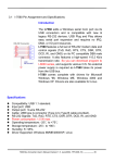
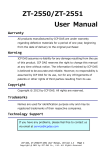
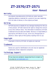
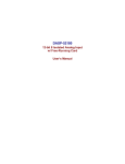
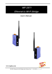
IR-210 Universal IR Learning Remote Module User Manual v1.0 www.icpdas.com IR-210 Universal IR Learning Remote Module (Ver. 1.0, Aug/12/2011) Warranty All products manufactured by ICP DAS are under warranty regarding defective materials for a period of one year from the date of delivery to the original purchaser. Warning ICP DAS assumes no liability for damages resulting from the use of this product. ICP DAS reserves the right to change this manual at any time without notice. The information furnished by ICP DAS is believed to be accurate and reliable. However, no responsibility is assumed by ICP DAS for its use, or for any infringements of patents or other rights of third parties resulting from its use. Copyright Copyright 2011 by ICP DAS. All rights are reserved. Trademark The names used for identification only may be registered trademarks of their respective companies. Document Revision Version 1.0 Author Bruce Date 2011-8-12 Description of changes First Release Revision IR-210 Universal IR Learning Remote Module (Ver. 1.0, Aug/12/2011) 1 Contents 1. Introduction .......................................................................................3 1.1 1.2 Features .................................................................................................. 4 Applications ............................................................................................. 4 2. Hardware ...........................................................................................5 2.1 2.2 2.3 Specifications .......................................................................................... 5 Appearance ............................................................................................. 6 Pin assignments ...................................................................................... 7 2.4 Wire connection....................................................................................... 8 2.4.1 RS-232 connection ........................................................................... 8 2.4.2 RS-485 connection ........................................................................... 9 2.4.3 IR output......................................................................................... 10 2.4.4 Power connection ........................................................................... 10 2.5 Watchdog setting .................................................................................... 11 2.6 Firmware update Switch ........................................................................ 12 2.6.1 Update firmware ............................................................................. 12 2.6.2 Firmware operation mode .............................................................. 13 2.7 LED Indicators ....................................................................................... 15 3. Software...........................................................................................17 3.1 3.2 The configuration tool– IR-210 Utility .................................................... 17 IR-210 Utility .......................................................................................... 18 3.2.1 Menu .............................................................................................. 18 3.2.2 Open/Close COM port .................................................................... 21 3.2.3 IR Learning Mode ........................................................................... 22 3.2.4 Test and Save Learned Commands ............................................... 22 3.2.5 Test the IR commands of IR-210 .................................................... 25 4. Learning IR command Example .....................................................27 4.1 4.2 4.3 4.4 4.5 4.6 4.7 4.8 IR-210 communication settings ............................................................. 27 Planning the devices and IR commands of the appliance’s controller ... 28 Learning and testing IR commands ....................................................... 29 Saving the learned IR commands to a file ............................................. 30 Saving the learned IR commands to the IR-210 .................................... 30 Test the learned IR commands of the IR-210 ........................................ 31 Load the learned IR commands from the file ......................................... 31 Load the learned IR commands from the IR-210................................... 31 5. The Modbus explanation of emitting IR command .......................32 6. Technical support ...........................................................................33 IR-210 Universal IR Learning Remote Module (Ver. 1.0, Aug/12/2011) 2 1. Introduction The Intelligent Home automation is the hot topic recently in the world. Every country is striving for developing various home application systems for better life now. However, in every family, there are many appliances with the low cost IR interface to be remote controlled by a handheld controller. And, there is not a standard of the IR control in these appliances. If we can manage these appliances, the power consumption will be managed more efficiently. Therefore, ICP DAS has developed various IR products to apply in home automation. Theses IR products will help users to control and integrate these IR appliances into a control system. And, by integrating the PAC and others series of ICP DAS, users can easily to establish the home automation system. IR-210 is a universal IR learning remote module which can learn IR remote commands of diverse electronic devices. The learning commands can be stored in the module or saved to a file. IR-210 supplies 6 IR output channels for individual or simultaneous control on multiple devices. The accompanied RS-232 and RS-485 interfaces with Modbus/RTU protocol provide more flexible expansion and control on the module. Besides, IR-210 software utility provides users with easy configuration, learning, test and storage of IR commands. As a replacement of IR remote controls and a module that can be easily integrated with Modbus master devices (e.g. PAC, PLC, PC… etc.), IR-210 is well-suited for smart home and building automation. The application architecture of IR-210 is as follows. IR-210 Universal IR Learning Remote Module (Ver. 1.0, Aug/12/2011) 3 1.1 Features 6 IR output channels for controlling multiple devices. 1 IR learning input. Supports 6 learning IR carrier frequencies: 32.768、36、37.037、38、40 and 56 kHz. Can learn and store 176 IR commands. Supports RS-232 and RS-485 serial interface. Supports Modbus/RTU protocol. Assignable 256 Modbus Network IDs. Baud rate settings: 9600, 19200, 38400, 57600 and 115200 bps. Configurable NONE / ODD / EVEN parity and 1 or 2 stop bits. Provides transmitting / learning / power indication LEDs. Built-in Watchdog. RoHS Compliance. 1.2 Applications Home Entertainment Devices Video Conferencing System Surveillance System e-Classroom service Lighting Scenario Control Home and Building Automation IR-210 Universal IR Learning Remote Module (Ver. 1.0, Aug/12/2011) 4 2. Hardware 2.1 Specifications Item IR-210 Hardware CPU 32-bit MCU IR Interface IR Output Channels 6 channels with 3.5 mm audio jack IR Learning Input 1 channel. Supports 6 IR carrier frequencies: 32.768, 36, 37.037, 38, 40, 56 kHz. UART Interface Connector 2-pin (RS-485) / 5-pin (RS-232, Power) screw terminal connecter COM1 RS-232 (TxD, RxD, GND) COM2 RS-485 (DATA+, DATA-) Baud Rate (bps) 9600, 19200, 38400, 57600, 115200 Protocol Modbus/RTU (slave) LED Round LED TR (IR Transmitting) / LN (IR Learning) / PWR (Power) Power Power supply +10 ~ +30 VDC Power Consumption 2.5 W Max. Dip Switch FW (Firmware update mode) / OP (Firmware operation mode) Mechanism Installation DIN-Rail Dimensions 33mm x 107mm x 78mm (W x H x D) Environment Operating Temp. -25 ~ +75 ℃ Storage Temp. -30 ~ +80 ℃ Humidity 10 ~ 90% RH, non-condensing IR-210 Universal IR Learning Remote Module (Ver. 1.0, Aug/12/2011) 5 2.2 Appearance Front Top Bottom Figure 2-1 The appearance of the IR-210 IR-210 Universal IR Learning Remote Module (Ver. 1.0, Aug/12/2011) 6 2.3 Pin assignments ● The front panel IR Output 1 ~ 6:3.5 mm audio jack Figure 2-2 IR output 3.5 mm audio jack ● Communication terminal Table 2-1 IR-210 terminal pin assignments Screw terminal connecter Interface RS-485 Pin RS-485 DATARS-485 DATA+ RS-232 TxD RS-232 RS-232 RxD Ground GND Power +Vs Field Ground F.G. Figure 2-3 Communication terminal IR-210 Universal IR Learning Remote Module (Ver. 1.0, Aug/12/2011) 7 2.4 Wire connection The IR-210 supports 2 communication ports. They are RS-232 and RS-485 interfaces. But, the only one interface can be used at the same time. The default interface is RS232 port. Note: The IR-210 utility can help users to change the communication port. The LEDs also can indicate which port is used when IR-210 reset. The front panel is 6 IR outputs with 3.5 mm audio jacks. 2.4.1 RS-232 connection The pin assignment of IR-210’s RS-232 port is as figure 2-4. Figure 2-4 RS-232 connection The following figure is using the attached cable (CA-0910) to apply in the RS-232 connection. If the host PC has no RS-232 port, the USB to RS-232 converters, I-7560 or I-7561 of ICP DAS, can be chosen to use. Figure 2-5 RS-232 connection cable (CA-0910) IR-210 Universal IR Learning Remote Module (Ver. 1.0, Aug/12/2011) 8 Figure 2-6 the connection between the CA-0910 and IR-210 2.4.2 RS-485 connection The RS-485 connection between the IR-210 and RS-485 host device is as the figure 27. Figure 2-7、RS-485 connection You can use the USB to RS-485 converter (tM-7561 or I-7561) in host PC to test the IR-210. IR-210 Universal IR Learning Remote Module (Ver. 1.0, Aug/12/2011) 9 2.4.3 IR output The front panel of the IR-210 has 6-ch IR outputs with 3.5 mm audio jack. The IR-210 supports TRS and TS connection jacks. The figure 2-8 shows the relation of IR output and TRS connector. The figure 2-9 shows the relation of IR output and TS connector. ●TRS ●TS Figure 2-8、TRS connection Figure 2-9、TS connection 2.4.4 Power connection The IR-210 supports +10~+30 VDC. The power connection is as the figure 2-10. Figure 2-10、Power connection IR-210 Universal IR Learning Remote Module (Ver. 1.0, Aug/12/2011) 10 2.5 Watchdog setting The watchdog is the system inside timer to reset system due to some fault conditions in some ms. The watchdog of the IR-210 can be enabled or disabled by JP1. It is needed to open the case of the IR-210 to set JP1. The setting of JP1 is as the figure 211. The default setting of watchdog is enabled. Enable (default) Disable Figure 2-11 JP1 setting IR-210 Universal IR Learning Remote Module (Ver. 1.0, Aug/12/2011) 11 2.6 Firmware update Switch There is a switch in the bottom of the IR-210 to set the update firmware mode. The explanation is as follows. 2.6.1 Update firmware Set the switch to “FW” and reset the power to let the IR-210 run into the update firmware mode. In the mode, you can use RS-232 port of the IR-210 to update firmware by CA-0910 cable as figure 2-13. Note: After updating the firmware, remember to set the switch to “OP” mode and reset the power. The IR-210 would run into operation mode. Figure 2-12 the FW mode in the switch Figure 2-13 The download cable For updating the firmware, you can use the Firmware_Update_Tool.exe program or IR-210 Universal IR Learning Remote Module (Ver. 1.0, Aug/12/2011) 12 Utility-> [function]-> [Tool] -> [Update Firmware to IR-210] to open the download tool. According to the following steps, you can finish the update firmware procedure as the figure 2-14. (1) Select “COM” and “COM Port” (2) Click “Browser” to select the firmware. (3) Click “Firmware Update” to start the update procedure. The result of the update would be shown in “Firmware Update” field. 1 2 3 Figure 2-14、Update firmware of IR-210 The firmware of IR-210 can be downloaded from: ftp://ftp.icpdas.com/pub/cd/usbcd/napdos/ir-210/firmware/ Firmware_Update_Tool can be downloaded from: ftp://ftp.icpdas.com/pub/cd/usbcd/napdos/ir-210/software/fw_update_tool/ 2.6.2 Firmware operation mode The firmware operation mode needs the switch to be set in “OP”mode as the figure 215 and reset the power. In this mode, users can set the parameters, learn IR commands and receive Modbus commands via the COM port of the IR-210. IR-210 Universal IR Learning Remote Module (Ver. 1.0, Aug/12/2011) 13 Figure 2-15 Set the switch to “OP” mode IR-210 Universal IR Learning Remote Module (Ver. 1.0, Aug/12/2011) 14 2.7 LED Indicators There are three LEDs in the IR-210 to show three states. The meanings of these states would be introduced below. (1) PWR LED : This LED would turn on always when the IR-210 is normal. (2) LN LED : This LED represents the learning mode of IR-210. When this LED is on, it shows the IR-210 is in learning mode. It would wait for the appliance controller to emit the IR signal. When finishing learning the IR command, the LED would turn off. (3) TR LED : This LED represents the IR output state or communication interface in the initial procedure. When the LED is turning on, it shows the IR-210 is emitting the IR signal. Besides, when power on, this LED flashes three times and turns off in three seconds. It shows the IR-210 is using RS-232 port to communicate with outside. If the LED is turning on in three seconds and turning off, it shows the communication port is RS-485. IR-210 Universal IR Learning Remote Module (Ver. 1.0, Aug/12/2011) 15 Table 2-2 the description of LEDs of IR-210 LED Description Flash three times when power on The IR-210 is using RS-232 port. Turn on 3 seconds when power on The IR-210 is using RS-485 port TR flashing IR channel is outputting LN on Waiting for IR signal LN off Finishing receiving IR signal PWR on /off TR, LN off;PWR on Normal / Fault TR, LN, PWR on Update firmware mode Operation mode Note Set the switch to “OP”or “FW” mode and reset the power. (Normal) (Update firmware) IR-210 Universal IR Learning Remote Module (Ver. 1.0, Aug/12/2011) 16 3. Software 3.1 The configuration tool– IR-210 Utility The IR-210 Utility is used for setting the IR-210’s parameters and learning IR commands. It is the .NET Framework 4 client profile program based on Microsoft OS via the RS-232 or RS-485 port of the host PC to communicate with the IR-210. Users can download the IR-210 Utility from: ftp://ftp.icpdas.com/pub/cd/usbcd/napdos/ir-210/software/Utility/ If the environment of .NET Framework 4 client profile is not available in the Microsoft OS, please download and install the redistributable packages as follows: Web Installer http://www.microsoft.com/download/en/details.aspx?id=17113 Standalone Installer http://www.microsoft.com/download/en/details.aspx?id=24872 Figure 3-1 The IR-210 Utility main window IR-210 Universal IR Learning Remote Module (Ver. 1.0, Aug/12/2011) 17 3.2 IR-210 Utility 3.2.1 Menu Table 3-1 explains the menu of the IR-210 Utility. Table 3-1 the items of menu Item File Sub item Description Load Commands from File Load the IR command file to the utility. Unload Commands Unload the IR commands from the utility. Save Commands to File Save the IR command to the defined file from the utility. Exit Exit by the utility. Download IR Commands to IR-210 Download the temporary IR commands of the utility to the flash memory of IR210. Load IR Commands from IR210 Load the temporary IR commands from the flash memory to the utility. IR-210 Basic Settings The basic settings of the IR-210. Reset Settings Reset the basic settings. Tool Update Firmware to IR-210 This function provides users to update the firmware of the IR-210. Help About IR-210 Utility The information of the IR-210. Download Setting (1) File ‧Load Command from File The saved file name is *.ird which includes the information of the learned IR commands. Click this item would pop up the window for users to select the saved file. Then, the IR commands would be downloaded to the utility. ‧Unload Commands This function would clear the temporary IR commands from the utility. The “Device Name” and “Command Name” list in “Test and Save Learning Commands” field would be recovered to the default values IR-210 Universal IR Learning Remote Module (Ver. 1.0, Aug/12/2011) 18 ‧Save Commands to File This function provides a dialog to save the temporary IR commands as the defined file. (2) Download ‧Download IR Commands to IR-210 This function can save the temporary IR commands to the flash memory of the IR210. That would appear the window to show the download information as the figure 3-2. After finishing the procedure, this window would close. Figure 3-2 Download the IR commands to the IR-210 ‧Load IR Commands from IR-210 The item provides the function to load the IR commands to the utility from IR-210’s flash memory. That would appear the window to show the download information as the figure 3-3. After finishing the procedure, this window would close. Figure 3-3 Load the IR commands from the IR-210 (3) Setting ‧IR-210 Basic Settings This function can show or set the basic information of IR-210 as the figure 3-4. IR-210 Universal IR Learning Remote Module (Ver. 1.0, Aug/12/2011) 19 Figure 3-4 The basic setting of the IR-210 These settings include: [1] COM Port : The COM port of IR-210 (RS-232/RS-485, default :RS-232) [2] Baud Rate : The baud rate of the COM port (9600~115200 bps,default: 115200) [3] Parity : Parity bit (NONE / ODD / EVEN,default:NONE) [4] Data Bits : Data bit (This value is fixed in 8) [5] Stop Bits : Stop bit [6] Net ID [7] GapTime (1 / 2, default:1) : Modbus Net ID (0~255, default:1) : The max interval time in the IR signals (figure 3-5). For example: increasing the time would have the better learning performance In Sharp remote controller. (6 ~ 65 ms, default:36 ms) Figure 3-5 A complete IR Command with a gat time When opening the “Basic Settings” window of IR-210 utility, the utility would get the basic setting from the IR-210. The “Set Temporarily” can set these settings to the IR210 temporarily. And these settings would recover the last setting after resetting the IR-210. The “Set Permanently” would change and save these settings immediately. That would not change the value after resetting the IR-210. IR-210 Universal IR Learning Remote Module (Ver. 1.0, Aug/12/2011) 20 (4) Tool ‧Update Firmware to IR-210 Open the “Update firmware” window. You can know the detail as section 2.4.1. (5) Help ‧About IR-210 Utility This function can shows the information of IR-210. The firmware version would be shown correctly if the communication is normal to the IR-210. 3.2.2 Open/Close COM port This field can set the communication parameters of COM port of the host PC to the IR210. Before communicating with the IR-210, make sure the wire connection is correct, and these settings are the same with ones in the IR-210. Figure 3-6 the communication window These settings are explained as follows: [1] COM Port : The COM port of IR-210 (RS-232/RS-485, default :RS-232) [2] Baud Rate : The baud rate of the COM port (9600~115200 bps,default: 115200) [3] Parity : Parity bit (NONE / ODD / EVEN,default:NONE) [4] Data Bits : Data bit (This value is always 8) [5] Stop Bits : Stop bit (1 / 2, default:1) [6] Net ID : Modbus Net ID (0~255, default:1) IR-210 Universal IR Learning Remote Module (Ver. 1.0, Aug/12/2011) 21 3.2.3 IR Learning Mode This interface as the figure 3-7 provides “Learn On” and “Learn Off” buttons. After clicking “Learn On” button, the IR-210 would turn into IR learning mode and the LN LED turns on to wait for the controller’s IR signal. The “Learn Off” would release the IR learning mode. Figure 3-7 open/close IR learning interface 3.2.4 Test and Save Learned Commands This interface provides the function to plan the IR command, IR learning information and test the learned IR commands as the figure 3-8. Figure 3-8 Test & save learned IR commands interface Set Device and Command Quantity The “Set Device and Command Quantity” button would pop up the dialog as the figure 3-9 ~ 3-11 to set the IR command information. The dialog provides three steps to plane these IR commands. ● Step 1:Set the number of the IR devices. The max number of controlled devices is 11. This function is convenient for users to manager these IR commands as various groups as the figure 3-9. IR-210 Universal IR Learning Remote Module (Ver. 1.0, Aug/12/2011) 22 Figure 3-9 The quantity setting of the device (Step1) ● Step 2:Define the device name and set the number of the IR command This step can set the name of the planned devices and the quantity of the IR command. The former of the name is the number of the device. The quantity of the IR command can not be over 176. When the number is over 176, the utility would pop up a warning dialog and shows the remnant number as the figure 3-11. Figure 3-10 Define the name and the quantity of the IR commands (Step2) Figure 3-11 The warring dialog ● Step 3:Define the IR command name This step can define the IR command name according to your need. It is convenient to know the IR command function. The former of the name is the number of the IR IR-210 Universal IR Learning Remote Module (Ver. 1.0, Aug/12/2011) 23 command. It can be the command reference of the inside IR-210. Figure 3-12 Define the name of the IR commands (Step3) Test and Save Learned Commands The functions in this interface are descried as follows: ● Device Name / Command Name list In “Device Name” and “Command Name” lists, you can review the IR command setting result. And, users can start to learn and test IR commands according to this plan setting. ● IR command learning state The rectangular graph in the left of “Command Name” field as the figure 3-13 shows the learned state of this IR command. The different color shows the different state as follows: Color Description Red Shows the IR learned command has been saved in the “Command Name” field Yellow Get the IR learned command temporarily. If other command name item has been selected, the data would disappear. White The IR command has no any the learned information. IR-210 Universal IR Learning Remote Module (Ver. 1.0, Aug/12/2011) 24 Figure 3-13 The IR learning state dialog ● Run Command When finishing learning IR command, users can test this IR command from the IR-210 by clicking “Run Command”. The IR output channels are defined by “Output Channel” list. ● Save this Cmd This function can save this learned IR command into the Utility. When finishing all the learned commands, selecting [File]->[Save Commands to File] can save to the backup file. ● Clear this Cmd Clicking “Clear this Cmd” button can remove the learned IR command in the Utility from the selected command. ● Clear All Cmds This button can clear all the learned IR commands in the Utility. The device and command names would not be changed. However, selecting [File]-[Unload Commands] can recovery the default setting including the device and command names. ● Output Channel The “Output Channel” list can define the IR output channels when test the learned commands. 3.2.5 Test the IR commands of IR-210 This function filed can help users to test the IR commands in the IR-210 with the defined IR command No. and output channel as the figure 3-14. By clicking “Transmit from IR-210” button, the defined IR command would emit from the selected output channel of the IR-210. At the same time, the Modbus RTU format is shown in this dialog. This Modbus format can help users to apply in the real system. IR-210 Universal IR Learning Remote Module (Ver. 1.0, Aug/12/2011) 25 Figure 3-14 The Modbus format IR-210 Universal IR Learning Remote Module (Ver. 1.0, Aug/12/2011) 26 4. Learning IR command Example Follow these steps in this chapter to operate the IR-210 correctly. And you can understand how to set and use the IR-210. Before learning this example, you need to check the connection between the IR-210 to the host PC is correct. 4.1 IR-210 communication settings The default communication parameters of the IR-210 are as follows: Item Default COM port RS-232 Baud rate 115200 bps Parity None Data bits 8 Stop bits 1 Modbus ID 1 In the main window, select the COM port of the host PC to connect to the IR-210. Then, click “Open” to open the COM port of the host PC. If the opening COM is successful, the “open” button would be disabled. Figure 4-1 Open the COM port of the Host PC IR-210 Universal IR Learning Remote Module (Ver. 1.0, Aug/12/2011) 27 4.2 Planning the devices and IR commands of the appliance’s controller Select “Set Device and Command Quantity”to open the planning setting dialog. And follow three steps to finish the procedure as the figure 4-2 below. Step 1:Set the quantity of the controlled devices as the figure 4-3. Step 2:Set the device name and the quantity of the need IR commands of these controlled devices as the figure 4-4. Step 3:Set the IR command name as the figure 4-5. The former of these names represent the no. of the devices or commands. These numbers would be used when communicating to the IR-210 by Modbus Commands. Figure 4-2 The planning button Figure 4-3 The quantity setting of devices Figure 4-4 The setting of IR commands IR-210 Universal IR Learning Remote Module (Ver. 1.0, Aug/12/2011) 28 Figure 4-5 The name setting of IR commands 4.3 Learning and testing IR commands Follow these steps to know how to learn and test IR commands as the figure 4-6: (1) Select the needed IR command form the “Device Name” and “Command Name” fields. (2) Click the “Learn On” button then the LN LED turns on. It shows the IR-210 is in learning mode. (3) Take the IR emitter of the appliance controller to the IR input of IR-210. The distance between the controller and the IR-210 is not far from 10 cm. Then, press the wanted button of the controller. If the signal is correct and the IR-210 has received the signal, the LN LED turns off and the IR data would be saved in the Utility. (4) Select the IR output channel. For example as the figure 4-6, the output channel is 1. (5) Take the IR emitter of first output channel of the IR-210 to the appliance. Click “Run Command” to emit the IR command from the IR-210. You can check the learned IR command is OK or not. If the learned IR command can not control the device, please repeat step 2 and step 3. (6) Select “Save this Cmd” to save this learned command in the IR-210 Utility as the figure 4-6. Repeat the above steps to learn all the IR commands IR-210 Universal IR Learning Remote Module (Ver. 1.0, Aug/12/2011) 29 2 1 4 5 2 6 3 Dist. ≤ 10 cm Figure 4-6 The steps to learn IR commands When finishing learning IR-command steps, it is needed to save these results into a file in [File] menu. Also, these learned commands can be saved in the IR-210 from “Transfer” menu. 4.4 Saving the learned IR commands to a file Select the [File]->[Save commands to file] to save the learned IR commands as a file. The attached file name is *.ird. 4.5 Saving the learned IR commands to the IR-210 After the learning IR command procedure or loading from the file, it is needed to download these settings to the IR-210 from [Transfer]-> [Download IR Commands to IR-210] in the menu as the figure 4-7. Figure 4-7 Saving the learned IR command to the IR-210 IR-210 Universal IR Learning Remote Module (Ver. 1.0, Aug/12/2011) 30 4.6 Test the learned IR commands of the IR-210 The “Test IR Commands in IR-210” field can help users to test the learned IR commands in the IR-210 as the figure 4-8. By clicking “Transmit from IR-210” button, the defined IR command would emit from the selected output channel of the IR-210. You can check the learned IR command is correct by this way. At the same time, the Modbus RTU format shows in this dialog. This Modbus format can help users to apply in the real system. Figure 4-8 Test the IR command by Modbus communication 4.7 Load the learned IR commands from the file Select [File]->[Load commands from file] in the menu bar to load the saved *.ird files into the IR-210 Utility. 4.8 Load the learned IR commands from the IR-210 Select [Transfer]->[Load IR Commands from IR-210] in the menu bar to load the IR commands from the IR-210 as the figure 4-9. Figure 4-9 Load the setting from the IR-210 IR-210 Universal IR Learning Remote Module (Ver. 1.0, Aug/12/2011) 31 5. The Modbus explanation of emitting IR command Table 5-1 is the explanation about Modbus RTU registers. That is to say. The Modbus host device can send the Modbus commands to the IR-210 to emit the defined IR commands from the specific output channel. Also you can refer to section 3.2.5 to understand the Modbus RTU format. The function code of Modbus to write data to Modbus registers is 16. The modbus address is 2 bytes. Table 5-1 Modbus Holding Registers in the IR-210 Start Address [4xxxx] Description 1103 (0x44F) [41104] The number of IR command (1 ~ 176) 1104 (0x450) [41105] IR output channels Settable value: 0x01 ~ 0x3F。The first bit represents 1st channel. The 6th bit represents the 6th channel. Example ‧1st output channel:0x01 == 00 0001 (Binary) ‧1st , 2nd and 6th output channels:0x23 == 10 0011 Table 5-1 is the example of Modbus command to emit IR signal from the IR210.(Modbus ID:1, the IR command No.:1, output channel:6) Table 5-2: A example of Modbus Command to IR-210 (Hex) Net ID FC* Start Addr. Word Count Byte Count IR No. Output Ch. CRC16 01 10 04 4F 00 02 04 00 01 00 20 D5 07 *FC is the abbreviation of Function Code. IR-210 Universal IR Learning Remote Module (Ver. 1.0, Aug/12/2011) 32 6. Technical support Email problem-report to [email protected] if you have any questions. IR-210 Universal IR Learning Remote Module (Ver. 1.0, Aug/12/2011) 33