1
Installation and Programming Manual
Installation and Programming Manual
Table of Contents
Chapter 1: Introducing WisDom .............................................................................................1-1
What is the WisDom? ......................................................................................................................... 1-1
WisDom Architecture and Capabilities............................................................................................. 1-2
WisDom Features ............................................................................................................................... 1-3
Technical Specifications.................................................................................................................... 1-4
Chapter 2: Mounting and Wiring the WisDom .......................................................................2-1
WisDom Installation Steps................................................................................................................. 2-1
WisDom Components ........................................................................................................................ 2-2
Mounting the WisDom........................................................................................................................ 2-3
Choosing the Mounting Location...............................................................................................................2-3
Wall Mounting the WisDom.......................................................................................................................2-3
Wiring the WisDom............................................................................................................................. 2-6
Connecting AC Power...............................................................................................................................2-6
Connecting Telephone Lines ....................................................................................................................2-6
Wiring the Bell Tamper..............................................................................................................................2-7
Wiring the Utility Outputs...........................................................................................................................2-7
Wiring the External Sounder .....................................................................................................................2-7
Ground Connection ...................................................................................................................................2-8
Wiring the Hardwire Zone .........................................................................................................................2-9
Connecting the Backup Battery.................................................................................................................2-9
Auxiliary Terminal ...................................................................................................................................2-10
Wired Expansion BUS Modules (Optional) .............................................................................................2-10
Jumpers Setting ......................................................................................................................................2-11
Adjusting the LCD Contrast.....................................................................................................................2-12
Chapter 3: Programming the WisDom ...................................................................................3-1
WisDom Programming Tools Options ............................................................................................. 3-1
Using the WisDom’s LEDs and Keys ............................................................................................... 3-2
Installer Programming from the WisDom Keys .............................................................................. 3-3
Accessing the Installer Programming Menu..............................................................................................3-3
Restoring Manufacturer’s Defaults ............................................................................................................3-5
Keypad Timeout........................................................................................................................................3-6
Using the Program Transfer Module (PTM) ..................................................................................... 3-3
Chapter 4: Using the Installer Programming Menus.............................................................4-1
Installer Programming Menu Conventions ...................................................................................... 4-1
System ................................................................................................................................................. 4-2
System: Timers .........................................................................................................................................4-3
System: Control ........................................................................................................................................4-4
System: Receiver ....................................................................................................................................4-11
System: Clock .........................................................................................................................................4-12
System: Labels .......................................................................................................................................4-13
System: Tamper Sound ..........................................................................................................................4-15
System: Default Jumper..........................................................................................................................4-15
ii
WisDom Installation and Programming Manual
System: Service Information................................................................................................................... 4-16
System: Version ..................................................................................................................................... 4-16
Zones ..................................................................................................................................................4-17
Zones: Allocation .................................................................................................................................... 4-17
Zones: Parameters ................................................................................................................................. 4-18
One by One....................................................................................................................................... 4-18
Zone Label ........................................................................................................................................ 4-20
Zone Partition.................................................................................................................................... 4-20
Zone Type......................................................................................................................................... 4-21
Zone Sound ...................................................................................................................................... 4-26
Zones: Testing........................................................................................................................................ 4-28
Zones: Editing ........................................................................................................................................ 4-29
Zones: Crossing ..................................................................................................................................... 4-31
Zones: Alarm Confirmation .................................................................................................................... 4-31
Outputs...............................................................................................................................................4-34
Output: Define ........................................................................................................................................ 4-34
Output: Nothing ................................................................................................................................. 4-35
Output: System ................................................................................................................................. 4-35
Output: Partition ................................................................................................................................ 4-36
Output: Zone ..................................................................................................................................... 4-38
Output: User Code ............................................................................................................................ 4-38
Output Pattern of Operation .............................................................................................................. 4-39
Activation/Deactivation...................................................................................................................... 4-40
Output Label ..................................................................................................................................... 4-40
Output A ................................................................................................................................................. 4-41
Output B ................................................................................................................................................. 4-41
Code Maintenance.............................................................................................................................4-42
Code Maintenance: Authority ................................................................................................................. 4-43
Code Maintenance: Partition .................................................................................................................. 4-44
Code Maintenance: Grand Master ......................................................................................................... 4-45
Code Maintenance: Installer................................................................................................................... 4-45
Code Maintenance: Sub-Installer ........................................................................................................... 4-46
Code Maintenance: Code Length ........................................................................................................... 4-47
Dialer...................................................................................................................................................4-48
Dialer: MS Telephone Numbers ............................................................................................................. 4-48
Dialer: MS Account Numbers ................................................................................................................. 4-50
Dialer: MS Communication Format......................................................................................................... 4-50
Dialer: UD Telephone Number ............................................................................................................... 4-52
Dialer: UD Access and ID....................................................................................................................... 4-52
Dialer: Controls....................................................................................................................................... 4-54
Dialer: Parameters.................................................................................................................................. 4-57
Dialer: Report Split ................................................................................................................................. 4-62
Dialer: Follow Me.................................................................................................................................... 4-64
Report Codes .....................................................................................................................................4-66
Report Codes: Auto Codes..................................................................................................................... 4-66
Report Codes: Manual Codes ................................................................................................................ 4-68
Report Codes: Emergency Key......................................................................................................... 4-68
Report Codes: Zones ........................................................................................................................ 4-69
Report Codes: Troubles .................................................................................................................... 4-70
Report Codes: Arm ........................................................................................................................... 4-72
WisDom Installation and Programming Manual
iii
Report Codes: Disarm .......................................................................................................................4-73
Report Codes: Wireless.....................................................................................................................4-73
Report Codes: Miscellaneous............................................................................................................4-74
Report Codes: Special Communication .............................................................................................4-75
Monitoring Station: Voice Alarm Verification......................................................................................4-76
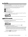
Key-Fobs ........................................................................................................................................... 4-77
Key-Fobs: Allocation ...............................................................................................................................4-77
Key-Fobs: Parameters ............................................................................................................................4-78
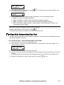
Key-Fobs: Communication Test..............................................................................................................4-79
Keypads............................................................................................................................................. 4-80
Keypads: Allocation ................................................................................................................................4-80
Keypads: Communication Test ...............................................................................................................4-81
Exit Programming............................................................................................................................. 4-82
Chapter 5: Installer Programming within the User Programming Menu .............................5-1
Programming the Voice Messages ................................................................................................... 5-1
Voice Messages Types .............................................................................................................................5-2
Message Structure ....................................................................................................................................5-2
Voice Message Labels ..............................................................................................................................5-3
Test Message ...........................................................................................................................................5-7
Local Announcement Messages ...............................................................................................................5-8
Walk Test ............................................................................................................................................. 5-9
Appendix A: Report Codes .................................................................................................... A-1
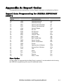
Report Code Programming for SESCOA SUPERFAST (03B1) ............................................................... A-1
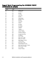
Report Code Programming for ADEMCO POINT (CONTACT) ID (0420) ................................................ A-2
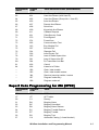
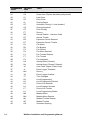
Report Code Programming for SIA Level 1 (0700) .................................................................................. A-3
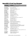
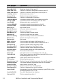
Appendix B: Event Log Messages......................................................................................... B-1
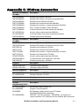
Appendix C: WisDom Accessories........................................................................................ C-1
iv
WisDom Installation and Programming Manual
Chapter 1: Introducing WisDom
This chapter provides a basic introduction to the WisDom system ,its architecture and
capabilities, as described in the following sections:
What is the WisDom? below
WisDom Architecture and Capabilities, page 1-2
WisDom Features, page 1-3
Technical Specifications, page 1-3
What is the WisDom?
The WisDom is a fully featured wireless security system, providing sophisticated solutions for
alerting and reporting premises alarm signals.
The WisDom has been specifically designed to meet a wide range of security needs of
homes, offices and small commercial applications.
The WisDom is simple and fast to install. It has a user friendly interface that enables easy
installation, programming and use. In addition, the WisDom can also be programmed and/or
controlled through local or remote Upload/Download software installed on a PC computer
with a Windows operating system.
It has a built in siren and it is designed around microprocessor and EEPROM (Electrically
Erasable Programmable Read-Only Memory) technology, which stores the system's
operating program, as well as its programmable parameters, without dependency on external
power sources.
The WisDom is available in two Radio Frequencies: 433.92 MHz and 868.65 MHz.
The WisDom main benefits are:
Installer Benefits:
Simple programming logic – fully menu driven
Wireless calibration and adjustable threshold level, enables higher false alarm immunity.
Actual transmitter signal strength and RF noise displayed on LCD, eliminating the need
for an external strength meter.
All detectors supervised for presence, low battery, jamming and tamper
Supports all major central station reporting codes.
User Benefits:
Full voice guide enables simple remote phone operation
Built in two-way voice communication to the premises.
Local announcement and feedback of system status.
Family message center.
Dedicated buttons for simple emergency notification
Quick key operation of users functions
Full control of voice messages and system sounds.
WisDom Installation and Programming Manual
1-1
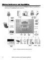
WisDom Architecture and Capabilities
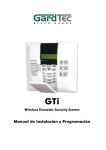
The following diagram provides an overview of the WisDom's architecture and capabilities.
Examine this figure before beginning your WisDom installation to obtain an overall picture of
the full extent of the WisDom system's capabilities.
Figure 1-1: WisDom Architecture and Capabilities
1-2
WisDom Installation and Programming Manual
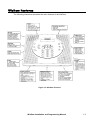
WisDom Features
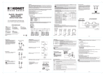
The following illustration describes the main features of the WisDom.
Figure 1-2: WisDom Features
WisDom Installation and Programming Manual
1-3
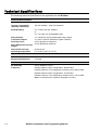
Technical Specifications
The following technical specifications are applicable for the WisDom:
Electrical Characteristics
System Power
220\110VAC, External Transformer 1500mA, 9VAC
Current Consumption
(Standby / Maximum)
250 mA standby / 1200 mA maximum
Backup Battery
6 x 1.5VDC Size AA, Alkaline
or
6 x 1.2V Size AA, rechargeable cells
Relay Outputs
2 x 3 Amps 24 VDC programmable relay outputs
Transistor Outputs
2 x 70mA 13.8VDC transistors (Open Collector)
Auxiliary Power
9V DC @ 200 mA maximum
Bell/LS(External) Sounder
Output
9V DC @ 500mA maximum
Internal Bell intensity
90 db /30 cm
Operating Temperature
0°C to 55°C (32°F to 131°F)
Physical Characteristics
Dimension
24 cm x 19 cm x 4.8 cm
Weight (with batteries)
0.970 Kg
Wireless Characteristics
RF immunity
20V/m 80MHz to 1GHz
Frequency
RWSAL0868xxA: Basic configuration, 868.65 MHz
RWSALV868xxA: Full configuration including voice, 868.65 MHz
RWSAL0433xxA: Basic configuration, 433.92 MHz
RWSALV433xxA: Full configuration including voice, 433.92 MHz
Note: xx represents the system’s language or country.
1-4
WisDom Installation and Programming Manual
Chapter 2: Installing the WisDom
This chapter covers the installation procedures of the WisDom, as follows:
WisDom Installation Steps, below
WisDom Components, page, 2-2
Mounting the WisDom, page 2-3
Wiring the WisDom, page 2-6
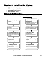
WisDom Installation Steps
The following workflow illustrates the recommended method for installing the WisDom.
A detailed description of each step is provided in the following sections of this manual.
1. Create an installation Plan.
See Chapter 2
Choose a mounting location near AC outlet,
telephone outlet and easy to operate.
2. Wire the WisDom.
See Chapter 2
Connect AC power, telephone line, outputs,
external sounder, ground connection, wired
zone and batteries
3. Power Up and Defaulting
6. Allocate and Mount the
Wireless Devices
See Chapter 4 page 4-17 for zones, page 477 for Key-fobs and page 4-80 for keypads.
Use the supplied devices instructions
7. Perform Comm. Test
See Chapter 4 page 4-28 for zones, page 479 for key-fobs and page 4-81 for keypads.
Perform a communication test for each device
as described in this manual.
8. Set Receiver Times
See Chapter 3 page 3-5 and Chapter 4 page
4-15.
Set the default jumper on both pins and power
up the system.
See Chapter 4 page 4-12.
Define jamming and supervision times in quick
key programming location: [#][1][3][2] / [3]
4. Enter Installer menu
9. Complete Programming
See Chapter 3 page 3-3.
To programming menu, from the user menu,
press: [*][9][Installer code][#]
See Chapter 4
Complete all programming parameters (zones,
dialer, utility outputs. etc)
5. Calibrate the Receiver
10. Exit Programming
See Chapter 4 page 4-11.
To calibrate the receiver press [1][3][1][#] from
the main installer menu.
See Chapter 4 page 4-82.
After exiting the installer programming menu
perform a Walk test [*][4][code][2] and check
communication with the Central Station
WisDom Installation and Programming Manual
2-1
WisDom Components
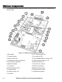
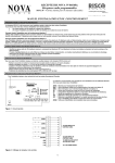
The illustration below shows the internal components when the front panel is separated from
the back plate.
Figure 2-1: WisDom Internal components Layout
1. Back panel
12. AC restore jumper (J6)
2. Tamper housing
13. Line seizure LED
3. Wires access hole
14. Rechargeable Battery Jumper (J10)
4. Telephone connectors (optional)
15. Utility outputs jumper (J4, J5)
5. AC connector (optional)
16. BUS connector (J1)
6. Ribbon Flat cable
17. Internal siren / buzzer
7. Front panel
18. Main terminal block
8. LCD back light trimmer
19. Battery locking screw
9. Tamper spring
20. Backup battery holder
10. Default jumper (J9)
21. Wall Mounting holes
11. Speaker
2-2
WisDom Installation and Programming Manual
Mounting the WisDom
Choosing the mounting location
Before you mount the WisDom, study the premises carefully in order to choose the exact
location of the unit for the best possible coverage and yet easily accessible to prospective
users of the alarm system.
The mounting place of the WisDom should be:
Try to centrally locate the system, as close as possible to the transmitters.
Near an uninterrupted AC outlet.
Near a telephone outlet.
Far from sources of interference, including:
Direct sunlight or heat sources
Electrical noise such as computers, televisions etc.
Large metal objects, which may shield the antenna.
In a place where the alarm can be heard during Stay arming mode.
Wall Mounting the WisDom
The WisDom is comprised of two sub-assemblies (front panel and back panel). It is mounted
on the wall, using the proper hardware, as described below.
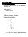
To mount the WisDom on the Wall:
1. Separate the two sub assemblies as follows:
Remove the case locking screw located at the bottom of the unit.
Press on the two locking tabs at the bottom of the unit (see figure 2-2).
Figure 2-2: Opening the WisDom casing
Gently hold the front panel from both sides, pull it up to a 45° angle and slide it to front
to release the front panel from the two locking tabs at the top of the unit, see figure 22. (DO not open the front cover to a larger angle in order not to break the two top tabs
at the top)
2. Disconnect the ribbon flat cable, leaving the flat cable connected to the front panel.
WisDom Installation and Programming Manual
2-3
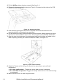
3. Pull the WisDom battery housing outward (See figure 2-1)
4. Release the back panel holding tabs (see Figure 2-3) located on both sides of the PCB
and pull out the PCB gently.
Figure 2-3: Releasing the PCB
5. Hold the back panel against the wall as a template and mark the locations for the
mounting holes (6 mounting holes are available).
6. Drill the desired mounting holes and place the screw anchors. When attaching the box to
the wall, it is recommended to use 4.2״mm, 32mm length screws (DIN 7981 4.2X32 ZP)
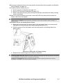
7. Open the wire entry knockouts in the back panel and insert the wires and cables via the
cable’s opening (including AC cable and telephone cable), see figure 2-4.
Figure 2-4: Open cable knockouts
8. Adjust the Tamper switch (using a flat screwdriver) according to your preferred
configuration.
Box only configuration – Triggers the tamper when the box is tampered.
Box and Wall configuration - Triggers the tamper when the box or the wall mounting
are tampered
9. Mount the back unit to the wall using the screws.
2-4
WisDom Installation and Programming Manual
10.Connect the desired wires to the back panel’s terminal block as illustrated in the WisDom
Wiring Diagram on page 2-6.
11.If desired, before closing the unit:
Set the jumpers as described on page 2-11.
Set the LCD contrast as described on page 2-12.
Return the battery housing (after placing the batteries) and attach the battery locking
screw (if required).
12.After the wiring connections are made, return the PCB to its place and reconnect the
ribbon cable to the front panel.
!
IMPORTANT:
Before wiring the WisDom, ensure that the connection to the power supplies, mains or battery, is
switched OFF.
13.Reattach the two sub-assemblies as follows:
Snap the front panel onto the upper tabs of the appropriate slots on the back panel
Pay attention to the placing of the tamper spring (see figure 2-5).
Push the bottom of the front panel onto the back panel so the locking tabs at the
bottom hold it.
Figure 2-5: Locking tabs and Tamper Spring
Reattach the case locking screw located at the bottom.
!
IMPORTANT:
Discharging Static Electricity: Please note that it is important to discharge static electricity that may have built up
in your body before you touch a circuit. To do this, touch the earth.
Following Local Regulations: Be sure to follow your local regulations regarding fire protection, electrical
installation, noise pollution, and security systems installation.
WisDom Installation and Programming Manual
2-5
Wiring the WisDom
This step explains the various wiring and connection procedures that must be performed
when wiring the WisDom, as follows
!
IMPORTANT:
Before wiring the WisDom, ensure that the connection to the power supplies, mains or battery, is
switched OFF.
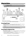
Figure 2-6: WisDom Wiring Diagram
Connecting AC Power
The WisDom is powered by a safety approved 220/110VAC to 9VAC 1500 mA transformer
(supplied, ROKONET part number 1ACA230V9V for 220 VAC to 9VAC).
1. Connect the transformer to an AC source and to the AC connector (optional) or the AC
terminals.
NOTES:
Do not connect the transformer to a power supply until you have completed all your wiring.
If you remove power from the unit (AC and battery), wait at least 10 seconds before reapplying power.
Connecting the Telephones Lines
Connect the system to a telephone line if the system is monitored or a remote connection to a
follow me number is required.
1. Connect the incoming telephone line to the PHONE LINE terminals or the optional plug-in
jack RJ11 marked as U3. (see figure 2-1).
2. Connect any telephone on the premises to the PHONE SET terminals or the optional
plug-in jack RJ31 marked as U2 - Line and Set, (see figure 2-1).
2-6
WisDom Installation and Programming Manual
BELL
TMP
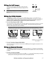
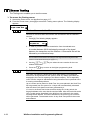
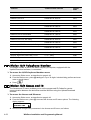
Wiring the Bell Tamper
COM
Connect the bell tamper to the BELL TMP and COM
terminals on the PCB’s block terminals using a 2.2 KΩ
resistor.
!
2.2 K EOL
RESISTOR
NOTE:
Bell tamper will be indicated only if the system parameter External Bell,
(quick key [1][2][31]) is defined as Yes. For more information refer to
page 4-10.
BELL TAMPER
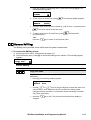
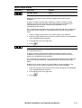
Wiring the Utility Outputs
The WisDom includes 4 utility outputs (2 x 24VDC 3Amps relays, 2 x 13.8 VDC 70 mA
transistor outputs). These outputs help operate external devices in response to a number of
system activities related to alarms, zones, partitions, general system events, actions of
particular user or scheduled events based on the system’s internal clock.
To wire Relay Outputs (UO1- UO2)
The connections of relay outputs UO1 and UO2 depend on the settings of jumpers J5 and J4
consecutively, which determine the outputs behavior. Wire the devices that you want to
activate to the outputs UO1-UO2, as follows:
c
NOTE:
The maximum current for UO1 and UO2 should not exceed 200 mA in POS or NEG configurations. In 1 PIN Only
configuration with an external power supply the maximum current for UO1 or UO2 should not exceed 3 Amps.
POS
COM
+
-
J4 (UO2)
or
J5 (UO1)
N.O
C
+
-
J4 (UO2)
or
J5 (UO1)
N.O
C
NEG
N.C
AUX
UO2 / UO1
Positive: The C terminal on
UO1/UO2 receives 9 VDC
+
1 PIN
Only
N.C
-
J4 (UO2)
or
J5 (UO1)
N.O
C
N.C
UO2 / UO1
UO2 / UO1
Negative: The C terminal on
UO1/UO2 receives COM
EXTERNAL
POW ER
1 PIN only: UO1/UO2 behave as
dry contacts
To wire Transistor Outputs (UO3-UO4)
Connect the positive connection of the device to AUX (+) and the negative connection to the
UO's (-) terminals.
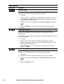
Wiring an External Sounder
The WisDom is equipped with a built-in sounder (see figure 2-1). If desired, an external bell
or piezo sounder can be connected to alert occupants and neighbors with a loud siren during
an alarm.
To wire an external sounder
1. Connect the external sounder wires to the BELL (+) (-) terminals. Ensure that you note the
polarity when connecting an electronic siren and/or polarized bells.
WisDom Installation and Programming Manual
2-7
2. Adjust the sound to be produced (See Chapter 4 page 4-10, quick key [1][2][32])
depending on the type of sounder.
For a loudspeaker without a built in siren driver, the WisDom produces a continuous or
interrupted oscillating voltage.
For a bell or electric siren the WisDom produces a steady 9VDC voltage or a slow
pulsating voltage, depending on the alarm type. Use a 9V 500mA maximum rated bell
sounder.
!
WARNING:
To avoid Bell Loop Trouble if NO connection is made to the BELL terminals, connect a 2200Ω resistor between
the terminals.
NOTES:
It is important to define the BELL/LS system control parameter correctly. The definition varies depending on the
type of sounder.
If the bell output is overloaded (exceeds 500 mA) and is shut down, you must disconnect the load from the output
for a period of at least 10 seconds before you reconnect any load to the auxiliary output
Ground Connection
Grounding provides a degree of protection against lightning and induced transients for any
piece of electronic equipment that may, due to lightning or static discharge, experience
permanent or general malfunctions. The ideal ground is considered to be a unified earth
ground in which an 8-foot copper-clad rod, located close to the existing power and telephone
ground rods, is sunk several feet into the earth. Appropriate hardware and clamps are then
used to electrically connect each of these rods together and then to the ground terminal of the
device to be protected.
It may be possible to use an existing electrical ground on the premises if one is close enough
to the WisDom. When connecting the ground wire, use a solid 14-gauge wire [or larger
(numerically lower) size]. Keep this wire as short as possible and do not run it in conduit, coil
it, bend it sharply, or run it alongside other wiring. If you must bend it or change its direction, it
should have a radius of at least 8 inches at the point from which it is bent. If in doubt, you
may want to enlist the help of a licensed electrician in matters concerning such grounding.
To connect to ground (Earth)
Connect between the WisDom’s ground terminal and an acceptable electrical ground
connection for the lightning transient protective devices in this product to be effective.
!
IMPORTANT:
Connecting to ground must be performed according to the local National Electrical Code.
2-8
WisDom Installation and Programming Manual
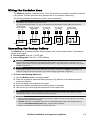
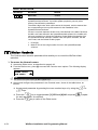
Wiring the Hardwire Zone
The WisDom supports 1 hardwire zone - Zone 33 which can be used for example to connect
a key switch. Connect this zone using twisted–pair or 4-conductor cable wiring.
The following diagram illustrates the various zone connections:
NOTE:
The hardwire zone cannot be used as a fire zone.
For a zone with a tamper switch, you can use a Double End-of-Line Resistor to save additional connections.
NORMALLY CLOSED
ZONE CONFIGURATION
zone
com
NORMALLY OPEN ZONE
CONFIGURATION
zone
END OF LINE ZONE
(N.C CONTACT)
com
zone
com
END OF LINE ZONE
(N.O CONTACT)
DOUBLE END OF LINE
ZONE CONFIGURATION
zone
zone
2.2 K
2.2 K
ALARM
ALARM
DETECTOR
DETECTOR
DETECTOR
com
2.2 K 2.2 K
ALARM
ALARM
ALARM
DETECTOR
com
TAMPER
DETECTOR
Connecting the Backup Battery
The WisDom has 6 backup batteries that are used in time of main power failure. The batteries
can be of two types:
Rechargeable: Size AA, 1.2VDC cells
Non rechargeable: Size AA, 1.5VDC Alkaline
!
IMPORTANT:
Use only Rokonet provided batteries (rechargeable Nickel Cadmium cylindrical cell 1.2V 800mA AA). Do not
attempt to use a different type of rechargeable batteries; failure to comply with the above instruction, may result in
damage to equipment.
!
CAUTION:
If rechargeable batteries are to be used, verify that J10 jumper is positioned on its two pins (see page 2-11)
Failure to comply with the above instruction, may result in damage to personnel or equipment.
To insert the Backup batteries:
1. Pull the WisDom battery housing outward.
2. Place the 6 batteries inside the battery housing. Pay attention to the batteries polarity
printed on the case.
3. Insert the battery housing back to its place.
4. Secure the battery housing with the locking screw (if required).
5. After all wiring is done plug the transformer into the wall outlet.
NOTE:
Rechargeable batteries should be charged for at least 12 hours to be fully charged. The “low battery” trouble
should disappear within 4 minutes after the battery is fully charged.
IMPORTANT:
1. When replacing the batteries be sure to buy the same type. Failure to comply with this instruction may result in
damage to personnel and/or equipment.
2. CAUTION: Replacing a rechargeable cell with a non-rechargeable battery might cause damage unless you
change the RECHARGABLE BATTERY jumper, located inside the WisDom.
3. Dispose of used batteries according to the proper instructions.
WisDom Installation and Programming Manual
2-9
Auxiliary Terminal
Use the Auxiliary Power AUX (+) COM (-) terminals to power devices that require a 9VDC
power supply with maximum current consumption of 200mA.
!
IMPORTANT:
During Main power failure the AUX output is deactivated to insure longer system backup time.
NOTES:
The total power from the AUX terminals should not exceed 200mA.
If the auxiliary output is overloaded (exceed 200mA) and is shut down, you must disconnect the load from the
output for a period of at least 10 seconds before you reconnect any load to the auxiliary output.
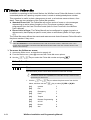
Wired Expansion Bus Modules (Optional)
The WisDom includes provision for wiring of optional expansion modules. This refers to the
set of 4 terminals located on the terminal block marked as AUX RED, COM BLK, BUS YEL
and BUS GRN. For example, to connect the X-10 interface module you should use the BUS
terminals. The connections for the expansion modules are terminal to terminal with colorcoded wires as follows:
BUS Terminal
Description
AUX RED
+12V power for BUS expansion modules
COM BLK
Black 0V common for BUS expansion modules
BUS YEL
Yellow DATA connection for BUS expansion modules
BUS GRN
Green DATA connection for BUS expansion modules
NOTE:
To prevent a possible drop down in voltage use a quality 4-conductor cable with an appropriate gauge size.
The maximum wire run permitted is 300 meters (1000 feet) for all legs of the BUS.
2-10
WisDom Installation and Programming Manual
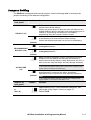
Jumpers Setting
The WisDom is equipped with internal jumpers. Use the following table to configure the
jumpers according to the desired configuration:
Jumpers on
front panel
Position
Function
Enables to default the panel and restore the WisDom to the
manufacturers default settings.
Position the jumper plug over both pins when reinstating factory
installed defaults values to the Main Panel programming (refer to
Chapter 3, Programming the WisDom) or for installing
programming using the Program Transfer module.
DEFAULT (J9)
Maintains the last programming setting and disables the restoring
of the WisDom to the manufacturers default settings.
(Default)
Position the default jumper plug over one pin for safekeeping.
Enables continuous battery charging. Use this setting when using
rechargeable batteries.
RECHARGEABLE
BATTERY (J10)
Disables battery charging. Use this setting when using nonrechargeable batteries.
(Default)
Battery Discharge Protection is ON: If a continuous AC power
outage occurs, the WisDom automatically disconnects the
battery when its backup battery voltage drops below 6.3 VDC, in
order to prevent "deep discharge” that may damage the battery.
NOTE:
In this position the WisDom will not start to operate from a battery power
supply, unless connected to the Mains first.
AC RESTORE
(J6)
(Default)
Battery Discharge Protection is OFF: The battery may be totally
discharged during continuous AC failure, thus battery
replacement may be required (no deep discharge protection).
NOTE:
In this position the WisDom will start to operate from a battery power
supply whether it is connected to the Mains or not.
Jumpers on
back panel
UO1 (J5)
Position
Function
or
Determines the UO1 / UO2 connection (behavior), see
“Wiring the Utility Output” section on page 2-7.
UO2 (J4)
Default: POS
WisDom Installation and Programming Manual
2-11
Adjusting the LCD Contrast
The WisDom includes a trimmer located on the PCB of the front panel, next to the default
jumper (see figure 2-1) that enables you to adjust the brightness and contrast of the LCD
display. It is recommended to adjust the LCD display after powering up the system but prior
to reattaching the two sub-assemblies when closing the unit.
To adjust the LCD contrast:
1. Using a Philips screwdriver turn the trimmer clock-wise or counter clock-wise until the
desired intensity is achieved
2-12
WisDom Installation and Programming Manual
Chapter 3: Programming the WisDom
The WisDom is designed around microprocessor and EEPROM (Electrical Erasable
Programming Read Only Memory), which stores the system’s operating program, as well as
its programmable parameters, without dependency of external power sources.
This chapter explains the WisDom programming options, how to use the keypad elements,
and the basics about programming via the keys. You can program the system at any time,
even before installing it. All you need is to apply temporary power to the unit.
For detailed information about each Programming option, refer to Chapter 4, Using the
Installer Programming Menus.
WisDom Programming Options
The WisDom can be programmed locally or remotely. The following describes the options to
program the WisDom :
Local operation using the numerical Keys and LCD Display: Instructions are provided
on page 3-3.
Program Transfer Module (PTM): (p/n RP128EE0000A) The PTM is a tiny circuit board
into which a copy of the WisDom's configuration can be copied and stored as well as
transferred to any installation when temporarily plugged into the 4-wire BUS connector.
For detailed instructions refer to page 3-6 .
Upload/Download (U/D): A software application that enables you to program the
WisDom from a PC computer. It offers the following two alternatives:
Working locally, through a portable computer connected to the WisDom
Working at a remote site, communicating with the WisDom via a phone line and
modem
When using the Upload/Download software, the following is required:
IBM compatible PC
Upload/Download software (p/n RP128UDIN00A)
BUS adapter (p/n RP296EBA000A) cable and plug to connect between the PC serial
COM port and the WisDom J1 BUS connector (for on-site use)
Modem with access to a phone line (for remote use). Recommended modem by
Rokonet is Hayes - OPTIMA 336.
USB/485 converter for on-site use (p/n RP128EUSB00A) to connect between a PC
USB port and the WisDom J1 serial connection. For additional details, refer to a
Rokonet technical support representative.
WisDom Installation and Programming Manual
3-1
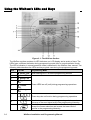
Using the WisDom’s LEDs and Keys
Figure 3-1: The WisDom Surface
The WisDom surface contains six LED indicators, an LCD display and a variety of keys. The
LEDs have a different indication during programming mode than in normal operation mode.
The LED’s indication in normal operation mode is described in the WisDom user manual. The
following table describes the LEDs and keys typical uses during the programming mode:
Item
3-2
Key/LED
Programming Mode
1
Power LED
2
Arm LED
3
Ready LED
4
Bypass
LED
5
Trouble
LED
6
Message
LED
Slow flashing LED = an active programming session
These LEDS are off (unlit) during programming operations.
7
These keys do not function during programming operations
8
Use this key to exit the current programming selection and
move up to the next higher level in the programming hierarchy.
9
Use this key to enter selected information into the system or to
accept the current selection and access the lower level of
options in the programming hierarchy
WisDom Installation and Programming Manual
Item
Key/LED
Programming Mode
10
LCD Program
Display
The LCD program display consists of two lines. The top line
displays information about the main selection mode, and the
bottom line displays information and/or data about the specific
option set. Such data may be changed through keypad
entry.When programming, up to 16-characters can be entered
into a line, as required.
11
12
These keys do not function during programming operations
0 through 9
Use the numbered keys, 0 through 9, to key in numbers and/or
special characters when labeling zones, areas, and partitions.
(For information about how to use the keypad for labeling
zones, areas, and partitions, refer to Chapter 4, Using the
Installer Programming Menus.)
13
Press either one of these keys to move back and forth through
the programming level functions.
These keys also change the position of the flashing cursor.
When editing a selection, the cursor moves to the left or right
respectively.
14
Use this key to toggle forward through the programming
choices within a selection.
15
Use this key to toggle backward through the programming
choices within a selection.
15
This key does not function during programming operations
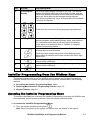
Installer Programming from the WisDom Keys
This section explains how to use the WisDom keys to access the Installer Programming
menu as well as how to restore the manufacturer's defaults, as described in the following
sections:
Accessing the Installer Programming Menu, below
Restoring Manufacturer's Programming Defaults, page 3-5
Keypad Timeout, page 3-5
Accessing the Installer Programming Menu
This section describes how to access the Installer Programming menu after the WisDom has
been defaulted, as well as how to access it from the regular operation mode.
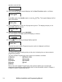
To access the Installer Programming Menu:
.
1. From the regular operation mode press
Note: When you power up the system for the first time, the display of the regular
WisDom Installation and Programming Manual
3-3
operation mode will be:
WisDom:
--:-- ... .. ...
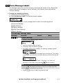
2. After pressing
the keypad displays the first User Functions option, as follows:
User functions:
1)Zone bypass
Press [9] to select the Installer option or use the
option, as follows:
key. The keypad displays the first
Installer:
1)Full prog.
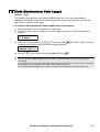
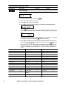
3. Press [1] Full prog. to enter the full programming menu. The display prompts you for
the Installer code, as follows:
Installer code:
4. Enter the default Installer Code: [0][1][3][3]
The code appears as
on the LCD display, as follows:
Installer code:
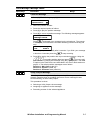
5. Press
The following message display appears:
Installation:
Please wait,
Then the first main Installer Programming menu option is displayed, as follows:
Programming:
1) System
The Power LED begins flashing slowly at this point, indicating that you have entered a
programming session.
The main Installer Programming menu options are available, as follows:
[1] System
[2] Zones
[3] Outputs
[4] Codes
[5] Dialer
[6] Report codes
[7] Key-fobs
[8] Keypads
[0] Exit
Each of the main Installer Programming menu options enables you to access and
program all of the WisDom options. Each option is also discussed in detail in Chapter 4,
Using the Installer Programming Menus.
3-4
WisDom Installation and Programming Manual
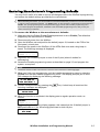
Restoring Manufacturer's Programming Defaults
You may find it useful to be able to remove all changes made to the WisDom’s programming
and restore the default settings provided by the manufacturer.
IMPORTANT:
Before defaulting the WisDom you should enable the Default Enable/Disable parameter that controls the authority
to restore to the manufacture’s defaults. The Default option for this parameter, as defined by the manufacturer is
Enable. The quick programming key for this parameter is [1][7] from the main installer-programming menu.
If you need to program this parameter, remember to exit the installer-programming menu, after you set your
choice, and save your selection.
To restore the WisDom to the manufacturer's defaults:
1. Make sure that the Default Enable/Disable parameter is set to Enable (The default as
supplied by the manufacturer is Enable)
2. Disconnect all power from the WisDom.
3. Open the WisDom unit and position the default jumper J9, located on the PCB of the
front panel, on both pins.
4. Reconnect the power to the WisDom. All the LEDs flash once and a long beep is
heard. The following message is displayed:
WisDom:
--:-- ... .. ...
5. Reposition the J9 default jumper on one of the J9 pins (where it resides for
safekeeping).
6. Access the installer-programming menu as described on page 3-3 and program the
system, as required.
NOTE:
Remember that the Installer Code has been restored to the manufacturer's default [0][1][3][3].
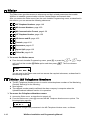
7. When you finish your programming, exit the installer-programming menu by selecting
[0] Exit from the main installer-programming menu. The display prompts you to save
your changes by displaying the following message:
DO YOU WANT TO
SAVE THE DATA? Y
8. Confirm saving the data by pressing the
following messages are displayed.
key. A short beep is heard and the
PLEASE WAIT
SAVING DATA..
9. When the function is completed, the display goes to regular operation mode, as
follows:
WisDom:
--:-- ... .. ...
If while exiting, the following display appears, this means that the J9 default jumper is
NOT positioned on 1 pin, but wrongly positioned on both J9 pins.
EE U/D ACCESSORY
NOT FOUND
WisDom Installation and Programming Manual
3-5
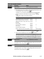
Keypad Timeout
If, after 15 minutes, during the installer programming, no entry is made to the keys the
WisDom will produce an audible reminder, consisting of several beeps in rapid succession,
along with the following display:
TIMEOUT
HIT ANY KEY
Pressing any key stops the beeping. To re-enter the Installer Programming menu, you must
key in your Installer code again and press
.
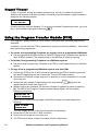
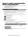
Using the Program Transfer Module (PTM)
The Program Transfer module (PTM) is used to create and apply standard programming
templates.
In addition, you can use the PTM on powered-up, properly functioning WisDom , which have
been previously programmed.
To create a Programming Template by copying from a programmed WisDom:
Use a programmed WisDom system to create a Programming Template to be applied to
other WisDom systems. The programming on the WisDom is ready for copying.
To install a Programming Template on a WisDom system:
Use an existing Programming Template on a PTM to install programming on a WisDom
system.
To copy from a programmed WisDom system into the PTM:
1. Position the PTM on the J1 BUS connector located on the PCB of the back panel with
the red LED not facing the row of terminals. The red LED flashes slowly.
2. Remove the J9 Default Jumper plug from its position on one pin and position it on both
of the two pins.
[9] [1] from the
3. Access the main Installer Programming menu by pressing
regular operation mode (see page 3-3).
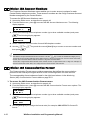
4. Without making any changes, exit the main Installer Programming menu by pressing
[0]. The LED on the Program Transfer module flashes rapidly, and the keypad
displays the following:
SAVING DATA IN
EE U/D ACCESSORY
When the LED stops flashing rapidly, the WisDom beeps twice and displays the
following:
DATA IS SAVED
PLEASE WAIT...
Then the display returns to the normal operation mode display.
5. Remove the PTM from the J1 BUS connector.
6. Position the J9 jumper on one of the pins.
7. The PTM now contains a copy of the Main Panel's configuration.
3-6
WisDom Installation and Programming Manual
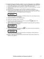
To load the Program Transfer module’s stored configuration into a WisDom:
1. Position the PTM on the J1 BUS connector located on the PCB of the back panel with
the red LED not facing the row of terminals. The red LED flashes slowly.
2. Remove the J9 Default Jumper plug from its position on one pin and position it on both
of the two pins.
3. Momentarily remove all power from the WisDom (both Mains and Battery).
4. Restore power to the WisDom. After a moment, the LED on the Program Transfer
module flashes rapidly, indicating that the information is being copied from the PTM to
the WisDom system. The LCD keypad displays the following:
ROKONET
PLEASE WAIT...
When the LED stops flashing rapidly, the WisDom beeps once, and its display returns
to the normal operation mode display.
5. Remove the PTM from the J1 BUS connector.
6. Position the J9 jumper on one of the pins.
[9] [1] from the
7. Access the main Installer Programming menu by pressing
regular operation mode (see page 3-3).
8. Without making any changes, exit the main Installer Programming menu by pressing
[0]. The following display appears:
DO YOU WANT TO
SAVE THE DATA? Y
9. Confirm saving the data by pressing the
following messages are displayed.
key. A short beep will sound and the
PLEASE WAIT
SAVING DATA..
Then the keypad returns to the normal operation mode display, and the WisDom’s
configuration now matches the PTM.
10.Reset its TIME and DATE, which were lost when power was removed. (Refer to the
WisDom User's Manual.)
WisDom Installation and Programming Manual
3-7
Chapter 4: Using the Installer
Programming Menus
This chapter describes the WisDom’s installer programming options and functions, as well as
all quick key shortcuts. They are presented in a table of menus are listed according to their
number, as follows:
1
System, page 4-2
2
Zones, page 4-17
3
Outputs, page 4-34
4
Codes, page 4-41
5
Dialer, page 4-48
6
Report Codes, page 4-66
7
Key-Fobs, page 4-77
8
Keypads, page 4-80
0
Exit, page 4-82
Installer Programming Menu Conventions
The following pages describe the options and functions that can be accessed via the WisDom
keys and how to program them.
Remember that these options are accessed from the Installer Programming menu, described
in Chapter 3, Programming the WisDom. Each procedure also provides information about
programming the system using the relevant Quick Keys.
The column headings appear as follows:
Column Heading
Description
Quick Keys
A shortcut to program an option. The shortcuts are listed in numerical
sequence.
Parameter
The name of the option programmed by the selection.
Default
The factory default. The default values have been carefully chosen
and are suitable for most installations. .
Range
Where applicable, the range of possible values.
WisDom Installation and Programming Manual
4-1
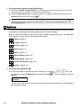
To program the system using Quick Keys:
1. Access the Installer Programming menu and select the main menu option that you want to
access (refer also to Chapter 3, Programming the WisDom).
2. Press the Quick Keys listed in sequence (from left to right) to locate the option listed in the
Parameter column and then press
.
NOTE:
When programming items in sequence, you can use the
key to toggle the options.
1
key to exit to the previous level and the
System
The System menu provides access to submenus and their related parameters that are used
for programming configuration settings applicable to the entire system.
After you access the System menu from the main Installer Programming menu, as described
in this section, you can access the following sub-menus:
1
1
Timers, page 4-3
1
2
Control, page 4-4
1
3
Receiver, page 4-11
1
4
Clock, page 4-12
1
5
Labels, page 4-13
1
6
Tamper Sound, page 4-15
1
7
Default jumper, page 4-15
1
8
Service Information, page 4-16
1
9
Version , page 4-16
To access the System menu:
From the Installer Programming menu, press [1], or press the
you find the number [1] System option and then press
appears:
or
keys until
. The first submenu (Timers)
System prog.:
1)Timers
You are now in the System menu and can access the required submenus, as described in
the following sections.
4-2
WisDom Installation and Programming Manual
1
1
System: Timers
The Time Define menu contains parameters that specify the duration of an action.
To access the Time Define menu:
1. Access the System menu, as described on page 4-2.
2. From the System menu, press [1] to access the Timers menu options. The following display
appears:
System timers:
1)Ex/En delay 1
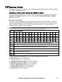
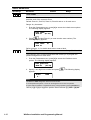
3. Access and configure the parameters in the Time Define menu, as follows:
System: Timers
Quick Keys
1
1
Parameter
Default
Range
30 seconds
1-255 seconds
45 seconds
1-255 seconds
45 seconds
1-255 seconds
60 seconds
1-255 seconds
04 minutes
01-90 minutes
Exit/Entry Delay 1
1
Exit/Entry Delays (Group 1).
1
1
1
1
Entry Delay 1
Duration of Group 1 Entry Delay.
1
1
1
2
Exit Delay 1
Duration of Group 1 Exit Delay.
1
1
Exit/Entry Delay 2
2
Exit/Entry Delays (Group 2).
1
1
2
1
Entry Delay 2
Duration of Group 2 Entry Delay.
1
1
2
2
Exit Delay 2
Duration of Group 2 Exit Delay.
1
1
3
Bell Timeout
Duration of the external sounder(s) during alarm.
1
1
4
Bell Delay
00 minutes
00-90 minutes
The time delay before the keypad sounder and the external sounder operates
after the onset of an alarm.
1
1
5
AC Off Delay Time
30 minutes
0-255 minutes
In the case of a loss of AC power, this parameter specifies the delay period
before reporting the event or operating the Utility Output.
If the delay time is set to 0 (zero), there will be no delay period
1
1
6
Phone Line Cut Delay
04 minutes
01-20 minutes
In the case of a cut phone line, this parameter specifies the delay period
before reporting the event into the event log or operating the Utility Output.
WisDom Installation and Programming Manual
4-3
System: Timers
Quick Keys
1
1
7
Parameter
Default
Range
Confirm Time Window
30 minutes
30-60 minutes
Specifies a time period that starts when an alarm is triggered for the first time.
If a second alarm is triggered before the end of the confirmation time window,
the WisDom will send a confirmed alarm to the Monitoring Station.
1
1
Start Confirmation
8
0 minutes
0-120 minutes
Specifies that the WisDom cannot start a sequential confirmation process until
the timer has expired. This time starts when the system has set and will
prevent confirmed alarms being generated in situations when a person has
been accidentally locked in the building.
1
2
System: Control
The System Control menu contains parameters that control specific system operations.
To access the System Control menu:
1. Access the System menu, as described on page 4-2.
2. From the System menu, press [2] to access the System Control menu options. The following
display appears:
System control:
01)Quick arm Y
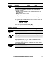
3. Access and configure the parameters in the System Control menu, as follows:
System: Control
Quick Keys
1
2
01
Parameter
Default
Range
Quick Arm
YES
YES/NO
YES: Eliminates the need for a User Code when arming in STAY or AWAY
modes.
NO: A valid User Code is required for arming in STAY or AWAY modes.
1
2
02
Quick UO
YES
YES/NO
YES: A user can activate a Utility Output without the need to enter a User
Code.
NO: A User Code is required to activate a Utility Output.
1
2
03
Allow Bypass
YES
YES/NO
YES: Permits zone bypassing by authorized system users after entering a
valid User Code.
NO: Zone bypassing is NOT permitted.
1
2
04
Quick Bypass
NO
YES/NO
YES: Eliminates the need for a valid User Code when bypassing zones.
NO: Qualified users must enter a valid User Code to bypass zones.
4-4
WisDom Installation and Programming Manual
System: Control
Quick Keys
1
2
05
Parameter
Default
Range
False Code Trouble
NO
YES/NO
YES: A False Code report is sent to the Central Station after three successive
attempts at arming or disarming in which an incorrect User Code is entered.
No alarm sounds at the premises, but a trouble indication appears on the
system's keypad(s).
NO: A local alarm is sounded at the premises.
1
2
06
Bell Squawk
YES
YES/NO
YES: If a keyswitch or a rolling code remote control is used, a brief "chirp" is
produced from the system's external sounder(s) (at the conclusion of the Exit
Delay period), as follows:
One chirp indicates the system is armed.
Two chirps indicate the system is disarmed.
Four chirps indicate the system is disarmed after an alarm.
NO: No "chirp" is produced.
1
2
07
Bell 30/10
NO
YES/NO
YES: The sounders cease to sound for 10 seconds after each 30 seconds of
operation.
NO: The sounders operate without interruption.
1
2
08
Phone Cut Alarm
NO
YES/NO
YES: Activates the sounders if the phone line is cut or the telephone service
is interrupted for the time defined in the Phone Line Cut Delay Time
parameter. (Refer to Phone Line Cut Delay Time, page 4-3.)
NO: No activation occurs.
1
2
09
3 Minute Bypass
YES
YES/NO
YES: Bypasses all zones automatically for 3 minutes when power is restored
to an "unpowered" system to allow for the stabilization of motion and/or
smoke detectors.
NO: No bypassing occurs.
1
2
10
Audible Panic
NO
YES/NO
YES: The sounders operate when a "Police Alarm" is initiated at the keypad
or when a Panic Zone is activated.
NO: No sounder operation occurs during a keypad "Police Alarm," making the
alarm truly "silent" (Silent Panic).
NOTE:
The system also transmits a Panic report to the Central Station.
1
2
11
Buzzer-->Bell
NO
YES/NO
YES: If an alarm occurs when the system is armed in the STAY mode, a
buzzer sounds for 15 seconds before the sounders operate.
NO: An alarm in the STAY mode causes sounders to operate simultaneously.
WisDom Installation and Programming Manual
4-5
System: Control
Quick Keys
1
2
12
Parameter
Default
Range
Fire Temporal Pattern
NO
YES/NO
YES: During a fire alarm, the sounders produce a pattern of three short
bursts, followed by a brief pause.
NO: During a fire alarm, the flow of sounds produced by the sounder is a
pattern of 2 seconds ON, then 2 seconds OFF.
1
2
13
Code Grand Master
NO
YES/NO
YES: Only a user with the Grand Master Authority Level can change all User
Codes, along with the TIME and DATE.
NO: Users with the Master and Manager Authority Levels can change their
own User Codes, all codes with a lower Authority Level, and the TIME and
DATE.
1
2
14
Audible Jamming
NO
YES/NO
Relates to the Jamming Time parameter, described on page 4-12.
YES: Once the specified time is reached, the WisDom activates the sounder
and sends a Report Code to the Central Station. (Refer to Jamming Trouble,
page 4-73.)
NO: Once the specified time is reached the sounders do not operate.
1
2
15
Technician Tamper
NO
YES/NO
YES: It is necessary to enter the Installer Code to reset a Tamper Alarm.
Therefore, Tamper Alarm resets require the intervention of the alarm
company. However, the system can still be armed.
NO: Correcting the problem resets a tamper Alarm, requiring no alarm
company help.
1
2
16
Technician Reset
NO
YES/NO
YES: It is necessary to enter the Installer Code to reset an alarmed partition
after it's been disarmed. This requires the intervention of the alarm company.
NOTE:
Before the READY LED can light, all zones within the partition must be secured.
NO: Once an alarmed partition is reset, the READY LED lights when all
zones are secured.
1
2
17
Abort Alarm
NO
YES/NO
YES: If an alarm is sent in error, it is possible for the Central Station to
receive an Abort Alarm Code, sent subsequent to the initial Alarm Code. This
happens if a valid User Code is entered to reset the alarm within 90 seconds
of initiation.
NO: No Abort Alarm Code can be sent once an alarm has been triggered.
1
2
18
Summer/Winter Clock
NO
YES/NO
YES: The WisDom automatically sets its Time of Day clock one hour ahead in
the spring (on the last Sunday in March) and one hour back in the Autumn (on
the last Sunday in October).
NO: No automatic time accommodation is made.
4-6
WisDom Installation and Programming Manual
System: Control
Quick Keys
1
2
19
Parameter
Default
Range
Forced Keyswitch Arming YES
YES/NO
YES: Keyswitch arming is performed on any partition. Any violated (not
READY) zone(s) in the partition will be bypassed automatically. The partition
is then "force armed," and all intact zones are capable of producing an alarm.
NO: The partition cannot be armed using a keyswitch until all violated (not
READY) zones are secured.
1
2
20
Pager
NO
YES/NO
Relates to the use of an alphanumeric pocket pager with the option to notify
the customer when an event occurs. The pager's phone number must be
programmed as a Follow-Me device in the WisDom's User Functions.
YES: When a call is made, event information is displayed on the
alphanumeric pager.
The following examples and tips clarify the YES option.
Enter the phone number, as described in the WisDom User's Manual, by
entering the letter [B] (which instructs the dialer to wait a fixed period of time
before continuing).
Add the partition number to which the Follow-Me relates.
The following messages are delivered automatically to the pager.
Displayed
Meaning
1#
The system (or partition) is armed.
2#
The system (or partition) is disarmed.
3#
The system (or partition) is in ALARM mode.
In the example below, the first column displays the characters that are
added after you enter the letter [B]:
Characters Added If Displayed
After [B]
Meaning
1
11#
Partition 1 is armed.
2
22#
Partition 2 is disarmed.
3
33#
Partition 3 is in ALARM mode.
NO: The WisDom calls a pager during an alarm situation only in the partition
for which it is programmed as a Follow-Me device. There are no
enhancements to the standard message.
WisDom Installation and Programming Manual
4-7
System: Control
Quick Keys
1
2
21
Parameter
Default
Range
Arm Pre-Warning
YES
YES/NO
Related to auto arm/disarm operation.
YES: For any partition(s) set up for Auto Arming, an audible Exit Delay
(warning) countdown will commence 4.25 minutes prior to the automatic
arming. (Refer to the user's Daily Arm function in the WisDom User's Manual
for additional details.)
During this period, Exit Delay beeps will be heard.
You can enter a valid User Code at any time during the countdown to delay
the partition's automatic arming by 45 minutes.
When an "auto-armed" partition is disarmed, as described above, it can no
longer be automatically armed during the current day.
The extended 4.25 minutes warning does not apply to automatic STAY mode
arming.
NO: Auto Arming for any programmed partition(s) takes place at the
designated time.
The programmed Exit Delay period and any audible signal occur as expected.
1
2
22
Low Battery Arm
YES
YES/NO
YES: Allows arming of the system when a low battery condition is detected.
NO: Arming the system is disabled when a low battery condition is detected.
1
2
23
Eng. Tamper
NO
YES/NO
YES: After a Tamper alarm, the system is not ready to arm. This requires the
intervention of the alarm company.
NO: After a Tamper alarm is restored the system is ready.
1
2
24
Blank Display
NO
YES/NO
YES: One minute after the last keypad operation, the display will appear
blank. After pressing any key, an Enter Code message will be displayed.
After the code is entered, the display returns to the normal operation mode.
NO: The LCD display operates normally.
1
2
25
24 Hour Bypass
NO
YES: A user can bypass a 24-hour zone.
NO: A user cannot bypass a 24-hour zone.
4-8
WisDom Installation and Programming Manual
YES/NO
System: Control
Quick Keys
1
2
26
Parameter
Default
Range
IMQ Install
NO
YES/NO
YES: Causes the following parameters to function as follows:
Auto Arm Bypass: If there is an open zone during the Auto Arm process,
the system will be armed, and a silent alarm will be activated (unless the
open zone is closed).
A utility output defined as “Auto Arm Alarm” (see page 4-37 ) is activated.
A utility output defined as “Zone Loss Alarm” (see page 4-38 ) is activated
NO: Causes the following parameters to function as follows:
Auto Arm Bypass: If the Auto Arm programming arms the system and
there is an open zone during the auto arm, the system will bypass the
open zones and arm the system.
A utility output defined as “Auto Arm Alarm” (see page 4-37 ) is
deactivated.
A utility output defined as “Zone Loss Alarm” (see page 4-38 ) is
deactivated
1
2
27
Grand Master
Authority/Partition
YES
YES/NO
YES: Specifies that the allowed partitions and the authority level of a user can
be changed by the Installer (Installer menu) or the Grand Master (User
menu).
NO: Specifies that only the Installer can change the partition and the authority
level of a user from the Installer programming menu.
1
2
28
Disarm Stop FM
YES
YES/NO
YES: The Follow-Me calls will stop when the partitions are disarmed by a
User Code.
NOTES:
When a latched keyswitch is activated, you can only disarm the system by releasing the
latched keyswitch.
When disarming from remote phone the Disarm Stop FM feature acts as NO even if it is
defined as YES.
NO: The Follow-Me calls will continue to be made when the partitions are
disarmed by a User Code.
1
2
29
Global Follower
No
YES/NO
YES: Specifies that all zones (that are programmed to follow an Exit/Entry
Delay time) will follow the Exit/Entry Delay time of any armed partition.
NO: Specifies that all zones (that are programmed to follow an Entry Delay
time) will follow the Entry Delay time of only the partitions to which they are
assigned.
WisDom Installation and Programming Manual
4-9
System: Control
Quick Keys
1
2
30
Parameter
Default
Range
Area
NO
YES/NO
Changes the system operation to Area instead of Partition, which then
changes only the operation of the common zone.
YES: When selected, the following points are relevant:
The common zone will be armed after any partition is armed.
The common zone will be disarmed only when all partitions are disarmed.
NO: When selected, the following points are relevant:
The common zone will be armed only when all partitions are armed.
The common zone will be disarmed when any partition is disarmed.
1
2
31
External Bell
NO
YES/NO
YES: Use this option when an external sounder is connected to the WisDom.
The WisDom supervises the Bell (+)(-) terminals and BELL TMP COM
terminals and announces troubles, events, alarms and reports.
To avoid Bell loop trouble, if no connection is made to the Bell (+)(-) terminals,
use a 2.2 KΩ resistor in its place.
To avoid tamper alarm, if no connection is made to the BELL TMP COM
terminals use a 2.2 KΩ resistor in its place.
No: Use this option when no external sounder is connected to the WisDom.
The WisDom’s Bell (+)(-) terminals and BELL TMP COM are not supervised.
There will not be an indication of bell loop trouble or bell tamper alarm if no
connection is made to these terminals.
1
2
32
Loudspeaker-No/Bell-Yes NO
YES/NO
YES: (For a bell or electric siren) A 9 VDC is produced at the Bell terminals
during burglary and panic alarm. A small pulsing voltage is produced during a
fire alarm.
No: (For a loudspeaker with no build in siren driver) The WisDom produces a
continuous oscillating voltage for burglary and panic alarms and an
interrupted oscillating voltage for fire alarms.
4-10
WisDom Installation and Programming Manual
1
3
Receiver
The Receiver menu contains parameters that control the WisDom receiver.
To access the Receiver menu:
1. Access the System menu, as described on page 4-2.
2. From the System menu, press [3] to access the Receiver menu options. The following display
appears:
Receiver:
1)Calibration
3. Access and configure the parameters in the Receiver menu, as follows:
System: Receiver
Quick Keys
1
3
1
Parameter
Default
Range
Calibration
Establishes the threshold level for jamming indication in order to eliminate false
jamming alarms.
Range for noise threshold: 00-99.
1. Press [1]. The following display appears, showing the current threshold
level:
Thold=XX
Re-calibrate?
N
2. To perform a new automatic calibration, use the
[Y] YES.
key to select
After the calibration process is finished, the new noise threshold is
displayed, as follows:
Thold=XX
New Thold=XX
3. To confirm the new threshold, press
,
-ORTo change the threshold manually, enter the required level and
press
.
NOTES:
In order to ensure that a momentary high noise level (due to environmental reasons) will not
cause a jamming alarm, you can set the noise level to be higher than the calibrated level.
WisDom Installation and Programming Manual
4-11
System: Receiver
Quick Keys
1
3
Parameter
Jamming Time
2
Default
No Jamming
detection
Range
NONE, 10, 20 or
30 seconds
Specifies the period of time that the WisDom's receiver tolerates unwanted
radio frequencies capable of blocking (jamming) signals produced by the
system's transmitters. Once the specified time is reached, the WisDom sends
a Report Code to the Central Station. (Refer to Jamming Trouble,
page 4-73.)
NONE: No jamming will be detected or reported.
NOTE:
Refer also to Audible Jamming, page 4-6. Different sounds will be produced when jamming
is detected, depending on the defined Audible Jamming time.
1
3
Supervisory (S.V.) Time
3
0 hours
0-7 hours
Specifies how often the WisDom checks for supervision signals, identifying
each of the system's transmitters. The WisDom generates a local trouble
signal identifying the zone of any transmitter from which a signal is not
received during the specified interval. Then it sends the Supervision Report
Code to the Central Station. (Refer to Report Codes: Zones trouble page 469.)
NOTES:
0 hours disables supervision.
It is recommended to set the supervision time to a minimum of 3 hours.
1
4
System: Clock
The Clock menu enables you to set the system's date and time.
To access the Clock menu:
1. Access the System menu, as described on page 4-2.
2. From the System menu, press [4] to access the Clock menu options. The following display
appears:
System Clock:
1)System time
3. Access and configure the parameters in the Clock menu, as follows:
System: Clock
Quick Keys
1
4
1
Parameter
Default
Range
System Time
00:00
HH:MM
Sets the current TIME (in 24-hour format).
1
4
2
System Date
JAN 01 2000 (SAT) MM DD YYYY (DAY)
Sets the current DATE. (Refer to Chapter 3, Programming the WisDom, for
instructions for using the keypad.)
4-12
WisDom Installation and Programming Manual
1
5
System: Labels
The System Labels menu enables you to modify the labels displayed by the LCD that identify
the system and partition labels.
Entering a New Label Using the WisDom Keys
You can rename the labels that identify zones and partitions by changing the default labels
(Partition 1, Partition 2, and so on) to, for example, The Jones's, Sales Dept, or Mastr
Bedr as appropriate.
To enter a new label:
Use the keys on the keypad to produce characters according to the table below. Pressing a
particular key toggles between the characters available from that key in the sequence listed
below followed by a blank space. The WisDom permits a total of 74 characters (letters,
numbers, and symbols) for use in labeling.
NOTE:
The data sequence of each key in the following table is suitable only for the English version.
KEY
DATA SEQUENCE
1
1
A
B
C
D
E
F
G
H
I
J
K
L
M
2
2
N
O
P
Q
R
S
T
U
V
W
X
Y
Z
3
3
!
''
&
'
:
–
.
?
/
(
)
4
4
a
b
c
d
e
f
g
h
i
j
K
l
m
5
5
n
o
p
q
r
s
t
u
v
w
X
y
z
6-0
Each of these keys toggles between producing their number and a blank space.
Use this button to toggle forward through the available characters.
Use this button to toggle backward through the available characters.
To move the cursor to the left.
To move the cursor to the right.
To enter a completed label into the system.
The number of allowed characters for each type of label varies, as follows:
Zone Label: Up to 15 characters
Partition Label: Up to 12 characters
Programmable Output Label: Up to 12 characters
Message to the User Label: Up to 12 characters
Service Information Label: Up to 16 characters
Service Name Label: Up to 16 characters
System Global Label: Up to 16 characters
User Label: Up to 10 characters
WisDom Installation and Programming Manual
4-13
To access the System Labels menu:
1. Access the System menu, as described on page 4-2.
2. From the System menu, press [5] to access the Labels menu options. The following display
appears:
Labels:
1)System
3. Access and configure the parameters in the System Labels menu, as follows:
System: Labels
Quick Keys
1
5
1
Parameter
Default
Range
System
WisDom
Any 12 characters
Edits the global (system) label for viewing during Download sessions.
1
5
2
1
5
4
to
Partitions 1 through 3
Partitions 1
through 3
Any 12 characters
Partitions 1 through 3.
Example: The example below describes how to edit each partition label.
TO ASSIGN THE JONES'S NAME TO PARTITION 1, FOLLOW THE STEPS
BELOW:
1. Press [1] for partition 1 and press
.
2. Press the [2] key repeatedly until a T appears in the display; press the
key once to move the cursor to the right.
3. Press the [4] key repeatedly until an h appears in the display; again, press
the
key to advance the cursor.
4. Press the [4] key repeatedly until an e appears and press the
advance the cursor.
key to
5. Press the [6], [7], [8], [9], or [0] key to create a space and press the
key to advance the cursor.
6. Press the [1] key until a J appears.
7. Use the elements of this procedure to assign the remaining Partition Labels.
4-14
WisDom Installation and Programming Manual
1
6
System: Tamper Sound
The Tamper Sound menu contains parameters that enable you to set the sound(s) that will be
produced by the WisDom after a Tamper violation of a zone, the WisDom box, wireless
keypad or any other device.
To access the Tamper Sound menu:
1. Access the System menu, as described on page 4-2.
2. From the System menu, press [6] to access the Tamper Sound menu options. The following
display appears:
Tamper sound:
5)Bell/A Buz/D
3. Access and configure the parameters in the Tamper Sound menu, as follows:
System: Tamper Sound
Quick Keys
1
6
1 to 5
Parameter
Default
Range
TAMPER SOUND
BELL/A BUZZER/D
1 to 5
Sets the sound(s) produced by a Tamper violation as follows:
Key
Sound
1
Silent
2
Bell (External Sounder) Only
3
Buzzer (Keypad Piezo) Only
4
Bell + Buzzer
5
Bell/A Buzzer/D
NOTE:
If you select the last option (5), during a Tamper alarm, a bell will sound when the system is
armed, and a buzzer will sound when the system is disarmed.
1
7
System: Default Jumper
Default: Enable
Range: Enable/Disable
The Default jumper parameter relates to what happens if the DEFAULT (J9) Jumper is in
place when power to the WisDom is switched off and then on.
To access the Default jumper menu option:
1. Access the System menu, as described on page 4-2.
2. From the System menu, press [7] to access the Default jumper menu option. The following
display appears:
Default jumper:
(J9) is enabled
WisDom Installation and Programming Manual
4-15
3. Select the required option, as follows:
ENABLE: The WisDom loses its programmed configuration, including all Labels and
User/Installer Codes. It returns to its original, factory default configuration. Any user
who knows the default User and Installer Codes can then reprogram it.
DISABLE: An unauthorized user cannot return the system to the manufacturer’s
default settings. The WisDom maintains its previously programmed configuration,
keeping all Parameters, Labels, and User/Installer Codes intact. As with any instance
of a total loss of power, you must reset the system's TIME and DATE.
1
8
System: Service Information
The Service Information menu enables to insert information accessible to the system's users
of the alarm company from whom the service is obtained.
To access the Service Information menu:
1. Access the System menu, as described on page 4-2.
2. From the System menu, press [8] to access the Service Information menu options. The
following display appears:
Service info:
1)Serv. Name
3. Access and configure the parameters in the Service Information menu, as follows:
System: Service Information
Quick Keys
1
8
1
Parameter
Default
Range
Service Name
Rokonet Security
Any 16 characters
Enables you to insert and/or edit the name of the alarm company from whom
service may be obtained. For additional details about how to enter a label,
refer to page 4-13).
1
8
2
Service Phone
System
Any 16 characters
Enables you to insert and/or edit the service phone number.
1
9
System: Version
The System Version menu supplies the current system version .
To access the System Version menu:
1. Access the System menu, as described on page 4-2.
2. From the System menu, press [9] to access the System Version menu option. The system
version with the software's checksum number is displayed.
4-16
WisDom Installation and Programming Manual
2
Zones
The Zones menu provides access to submenus that are used for programming, defining,
editing and testing each of the system's protected zones.
After you access the Zones menu from the main Installer Programming menu, as described in
this section, you can access the following submenus:
2
1
Allocation, page 4-17
2
2
Parameters, page 4-18
2
3
Testing, page 4-28
2
4
Editing, page 4-29
2
5
Crossing, page 4-31
2
6
Alarm Confirmation, page 4-32
To access the Zones menu:
From the main Installer Programming menu, press [2], or press the
until you find the number [2] Zones option and then press
(Allocation) appears:
or
keys
. The first submenu
Zones:
1)Allocation
You are now in the Zones menu and can access the required submenus, as described in
the following sections.
2
1
Zones: Allocation
The Zone Allocation menu enables to allocate the data it receives from any of the system’s
wireless transmitters in a process often referred to as WRITE mode. For additional
information refer to the instructions supplied with each transmitter.
To access the Allocation menu:
1. Access the Zones menu, as described on page 4-17.
2. From the Zones menu, press [1] to access the Allocation menu options.
3. Specify a two-digit zone number intended for the first wireless transmitter and press
The following display appears:
Zone:xx
1)Skip
2
1
.
(Alloc)
ZZ
Skip
1
Skip to the next transmitter assignment
WisDom Installation and Programming Manual
4-17
2
1
ZZ
Re (Write)
2
Overwrite the data into the selected location and allocate the transmitter to a
zone (within 255 seconds), according to the instructions supplied with each
transmitter. If the WisDom successfully recognizes the transmitter it will sound
a confirmation beep.
2
1
ZZ
Delete
3
Erase the allocation data in the selected location and then press [Y] YES or
[N] NO to confirm your choice
2
1
ZZ
Supervision
4
Choose supervision and then press [Y] YES or [N] NO to confirm your choice
2
2
Zones: Parameters
The Parameters menu provides access to submenus and their related parameters that are
used for programming the characteristics of each of the system's protected zones.
You can program by zone or by category. The first submenu allows you to program all
parameters for each zone one by one. You can also program one or more zones by category
using the following sub-menus: label, partition, Zone Type, Zone Sound and force arming.
After you access the Parameters menu from the main Installer Programming menu, as
described in this section, you can access the following submenus :
One by one
Zone Label
Partitions
Type
Zone Sound
Force Arming
Zones: Parameters
Quick Keys
2
2
1
Parameter
Default
Range
One By One
The one by one option enables to program the full complement of parameters
for each zone on a one-by-one basis
1. Specify a two-digit zone number from which you want to start programming
(for example, 01) and press
Label
2. Assign a label and press
again to access the category zone
to proceed to Zone partitions.
3. Use keys [1] to [3] to toggle the partition status between [Y] YES and [N]
No. Press
to proceed to Zone Type.
4. To program Zone Type, as well as the other zone categories, select the
following options (refer to the following pages for further instructions)
4-18
WisDom Installation and Programming Manual
Zones: Parameters
Quick Keys
Parameter
Default
Zone Type: Select a type and press
Range
.
Zone Sound: Select a sounding method and press
.
IMPORTANT:
When using the One by One method, the listing of each zone's parameters is
sequential. Once Zone 1's parameters have been programmed, they are followed by
Zone 2's, then Zone 3's, and so forth.
To program one or more of the system's zones using the One by One method, changes
made to any (or all) of the Zone parameters will NOT be recorded without going
through the One by One list, ending with the Zone sound parameter of the last zone
you want to program.
After making changes to the Zone Sound parameter, press
. This produces a
one-second tone and assures that change(s) you make to the zone programming are
recorded when you exit the One by One programming mode.
Zone 33 (Wired zone)
Zone 33 is defined in the WisDom as a wired zone. Therefore, during the One
By One option it has two additional parameters which follow the sound
definitions and apply only for this wired zone:
Zone termination
Zone loop response
Zone Termination:
The Termination menu enables you to program the connection type used for
the wired zone, zone 33. The actual (physical) termination for each zone must
comply with that selected in the zone termination menu.
N/C: (Normally Closed) Uses normally-closed contacts and no
terminating End-of-Line Resistor.
EOL: (End of Line) Uses normally-closed (NC) and/or normally-open
(NO) contacts in a zone terminated by a supplied 2200Ω End-of-Line
Resistor
DEOL: (Double End of Line) Uses normally-closed (NC) contacts in a
zone using at least two 2200Ω End-of-Line Resistors to distinguish
between alarms and tamper conditions
N/O: (Normally Open) Uses normally-open contacts and no terminating
End-of-Line Resistor
NOTE:
See Wiring diagram in Chapter 2, Wiring the hardwire Zone , page 2-9.
Zone Loop Response:
The Loop Response menu enables you to set the different times for which a
zone 33 violation must exist before the zone will trigger an alarm condition.
The following option are available:
1) Normal: 400 ms (milliseconds)
7) 2 hours
2) Long: 1 second
8) 2.5 hours
3) Fast: 10 ms (milliseconds)
9) 3 hours
4) 0.5 hours
10) 3.5 hours
5) 1 hour
11) 4 hours
6. 1.5 hours
WisDom Installation and Programming Manual
4-19
Zones: Parameters
Quick Keys
2
2
2
Parameter
Default
Range
Zone Label
The Zone Label menu enables you to create and/or edit up to 15 characters to
describe each of the system's zones.
Default: Zone 01, Zone 02, Zone 03, Zone 04 and so on for each zone
Range: Any characters
1. From the Parameters menu, press [2] to access the Labels menu options.
The following display appears:
Zone label:
Zone:01
(01-33)
2. Press
to label Zone 01 (or enter another zone number). The
following display appears:
Zone label:
Zone 01
01
Refer to page 4-13, for details about how to enter a label.
2
2
3
Zone Partition
Range: Partition 1-3
The Partitions menu contains parameters that enable you to program the
partition assignment for each zone.
1. From the Parameters menu, press [3] to access the Partitions menu
options. The following display appears:
Zone partition:
Zone:01
(01-33)
2. Specify a two-digit zone number and press
appears:
P=123
Y..
. The following display
Z=XX
NOTE:
The XX in the Z=XX designation refers the zone number.
In a multi-partitioned system, a zone can be assigned to more than one partition.
A system without partitions is regarded as having a single partition (meaning Partition 1).
Use keys [1] to [3] to toggle the partition status between [Y] YES or [N] NO.
4-20
WisDom Installation and Programming Manual
Zones: Parameters
Quick Keys
2
2
Parameter
Default
Range
Zone Type
4
The Zone Type menu contains parameters that enable you to program the
zone type for any zone. Setting the zone type is partly determined by the
arming levels, as follows:
Disarm: The system reacts only to those zones defined as 24 HR, Fire,
Panic, and Trouble.
Arm: The system reacts to all zones.
Stay: The system does not react to zones defined as internal (home). This
setting allows freedom of movement in those zones.
There are 22 zone types in the system, as described in the following
procedure.
From the Zones menu, press [3] to access the Zone Type menu options. The
following display appears:
Zone type:
Zone:01
(01-33)
Specify a two-digit zone number and press
.
Access and configure the parameters in the Zone Type menu, as follows
Parameters: Zone Type
Quick Keys
2
2
4
ZZ
+
Parameter
Default
Not Used
NONE
Arming Level/
Range
00
Disables a zone. All unused zones should be given this designation.
2
2
4
ZZ +
Exit/Entry 1
Arm/Stay
01
Used for Exit/Entry doors.
Zones in the Exit/Entry path, that when violated do not cause an intrusion
alarm during the Exit/Entry Delay periods (refer to Exit/Entry Delay 1 and
Exit/Entry Delay 2, page 4-3).
A zone must be secured during arming and when the delay expires. Use this
zone to trigger the entry delay.
2
2
4
ZZ +
Exit/Entry 2
ARM/STAY
02
Same as above, except that the Exit/Entry 2 time period applies.
WisDom Installation and Programming Manual
4-21
Zones: Parameters
Quick Keys
2
2
4
ZZ +
Parameter
Default
Range
Exit (OP)/Entry
Default for zone 1
ARM/STAY
03
Used for an exit/entry door, open during the armed period.
This zone behaves as described in the Exit/Entry 1 parameter, shown above,
except that, if faulted when the system is being armed, it does NOT prevent
arming.
To avoid an intrusion alarm, it must be secured before the expiration of the
Exit Delay period.
2
2
4
ZZ +
Entry Follower
Default for zone 2
ARM/STAY
04
Usually assigned to motion detectors and to interior doors protecting the area
between the entry door and the WisDom.
This zone(s) causes an immediate intrusion alarm when violated unless an
Exit/Entry zone was violated first. In this case, Entry Follower zone(s) will
remain bypassed until the end of the Entry Delay period.
2
2
4
ZZ +
Instant
Default for all zones
except 1 and 2
ARM/STAY
05
Usually intended for non-exit/entry doors, window protection, shock detection,
and motion detectors.
Causes an immediate intrusion alarm if violated after the system is armed or
during the Exit Delay time period.
When Auto Arm and Pre-Warning are defined, the instant zone will be armed
at the end of the Pre-Warning time period.
2
2
4
ZZ +
I+ Exit/Entry 1
Arm
(Interior +Exit/Entry 1)
06
Used for Exit/Entry doors, as follows:
If the system is armed in the AWAY (ARM) mode, the zone(s) provide a
delay (specified by Exit/Entry 1) allowing entry into and exit from an armed
premises.
If the system is armed in the STAY mode, the zone is bypassed.
IMPORTANT:
For greater security when arming in the STAY mode, it is possible to eliminate the Entry
Delay period associated with any zone(s), classified as Exit/Entry Delay 1 by pressing the
key twice, one after another. In effect, this makes it an INSTANT zone during the
STAY mode of operation.
2
2
4
07
ZZ +
I+Exit/Entry 2
(Interior+Exit/Entry 2)
Arm
Same as the I+Exit/Entry 1 parameter, described above, but the Exit/Entry 2
time period is applicable.
4-22
WisDom Installation and Programming Manual
Zones: Parameters
Quick Keys
2
2
4
Parameter
ZZ +
08
Default
Range
I+Exit(OP)/Entry
(Interior+Exit(OP)/Entry)
Arm
Used for an exit/entry door that, for convenience, may be kept open when the
system is being armed, as follows:
In AWAY (ARMED) mode, refer to the explanation in Zone Type 03,
page 4-22.
In STAY (ARMED) mode, the zone will be bypassed.
2
2
4
ZZ +
09
I+Entry Follow
(Interior+Entry Follower)
Arm
Generally used for motion detectors and/or interior doors (for example, foyer),
which would have to be violated after entry in order to disarm the system, as
follows:
In AWAY (ARM) mode, refer to the explanation in Zone Type 04, page 422.
In STAY (ARM) mode, the zone will be bypassed.
2
2
4
ZZ +
I+Instant (Interior+Instant)
Arm
10
Usually intended for non-exit/entry doors, window protection, shock detection
and motion detectors.
In AWAY (ARM) mode, a violation of this zone after the system is armed or
during the Exit Delay time period causes an immediate intrusion alarm.
In STAY (ARM) mode, the zone is bypassed.
2
2
4
ZZ +
UO Trigger
Arm
11
For a device or zone, which if violated at any time triggers a previously
programmed Utility Output, capable of activating an external indicator, relay,
appliance, and so on.
2
2
4
ZZ +
Day Zone
Arm
12
Usually assigned to an infrequently used door, such as an emergency door or
a movable skylight. Used to alert the system user if a violation occurs during
the disarmed period (trouble by day; burglary at night), as follows:
With the system armed (either AWAY or STAY), the zone acts as an
instant zone. A violation of this zone after the system is armed or during
the Exit Delay time period causes an immediate intrusion alarm.
With the system disarmed, a violation of this zone attempts to alert the user
by causing the TROUBLE LED to flash rapidly. This directs the user to
view the system's TROUBLE indications.
Optionally, such a violation can be reported to the Central Station as a
Zone Trouble. (Refer to Report Codes: Miscellaneous, page 4-69)
WisDom Installation and Programming Manual
4-23
Zones: Parameters
Quick Keys
2
2
4
Parameter
ZZ +
Default
24 Hours
Range
All
13
Usually assigned to protect non-movable glass, fixed skylights, and cabinets
(possibly) for shock detection systems.
A violation of such a zone causes an instant intrusion alarm, regardless of the
system's state.
2
2
4
ZZ +
Fire
All
14
For smoke or other types of fire detectors. This option can also be used for
manually triggered panic buttons or pull stations (if permitted), as follows:
If violated, it causes an immediate fire alarm, and the Arm LED is lit.
A fault in the wiring to any fire zone causes a Fire Trouble signal (a rapid
flashing of the trouble LED).
NOTE:
Zone 33 cannot be defined as a Fire zone
2
2
4
ZZ +
Panic
All
15
Used for external panic buttons and wireless panic transmitters.
If violated, an immediate panic alarm is sounded (if the zone sound is not
defined as silent), regardless of the system's state. An alarm display will not
appear on the keypads.
2
2
4
ZZ +
Special
All
16
For external auxiliary emergency alert buttons and wireless auxiliary
emergency transmitters.
If violated, an immediate auxiliary emergency alarm is sounded, regardless of
the system's state.
2
2
4
ZZ +
Pulse Keyswitch
17
Used to arm/disarm the system.
Connect an external momentary action keyswitch to any zone terminals given
this designation.
4-24
WisDom Installation and Programming Manual
Zones: Parameters
Quick Keys
2
2
4
Parameter
ZZ +
Default
Range
Exit Termination
18
This type of zone is used to avoid a false alarm by acting like an Exit
(OP)/Entry zone (see Exit (OP)/Entry, see page 4-22).
When triggered (after arming the system and closing the door or opening the
door, arming the system, and closing the door), the system's Exit Delay time
period will be shortened to 3 seconds.
When you re-open the door, the entry time restarts.
2
2
4
ZZ +
Latch Keyswitch
19
Connect an external SPST latched (non-momentary) keyswitch to zone 33 or
to any other wireless device as follows:
After arming one or more partitions using the keyswitch and then disarming
using the keypad, the related partitions will be disarmed. In order to arm
the partition using the keyswitch again, turn the key to the disarm position
and then to the arm position.
If a keyswitch latch is assigned to more than one partition and one of the
partitions is armed by using the keypad (the keyswitch stays in the disarm
position), then:
When changing the position of the keyswitch to the arm position, all the
disarmed partitions, which belong to this keyswitch, will be armed.
When turning the keyswitch to the disarm position, all the partitions will
be disarmed.
2
2
4
ZZ +
Entry Follower + Stay
All
20
Assigned to motion detectors and to interior doors protecting the area between
the entry door and the keypad, as follows:
In STAY (ARM) mode, a zone(s) given this designation behaves like an
Exit/Entry zone and is subject to the Entry and Exit Delay time periods
specified under Exit/Entry Delay 1. (Refer to Exit/Entry Delay 1, page 4-3.)
In AWAY (ARM) mode, a zone(s) given this designation behaves like an
Entry Follower Zone and causes an immediate intrusion alarm when
violated unless an Exit/Entry zone was violated first.
If so, an Entry Follower + Stay zone(s) remains bypassed until the end of
the Entry Delay period.
2
2
4
ZZ +
Keyswitch Delay
21
Used to apply the Exit/Entry Delay 1 parameter to the momentary keyswitch
operation.
WisDom Installation and Programming Manual
4-25
Zones: Parameters
Quick Keys
2
2
4
Parameter
ZZ +
Default
Range
Latch KSW Delay
22
Used to apply the Exit/Entry Delay 1 parameter to the latched keyswitch
operation.
2
2
Zone Sound
5
The Zone Sound menu contains parameters that enable you to program the
sound produced when a system zone triggers an alarm. Reports to the Central
Station are not affected by any of the options in this menu
1. From the Parameters menu, press [5] to access the Zone Sound menu
options. The following display appears:
Zone sound:
Zone:01
(01-33)
2. Specify a two-digit zone number and press
.
3. Access and configure the parameters in the Zone Sound menu, as follows
Parameters : Zone Sound
Quick Keys
2
2
5
Parameter
ZZ +
Default
Silent
1
Produces no sound.
2
2
5
ZZ +
Bell Only
2
Activates the bell sounders for the duration of the Bell Timeout period, or until a
User Code is entered, followed by use of the
2
2
5
ZZ +
key.
Buzzer Only
3
Activates each keypad's internal piezo buzzer.
2
2
5
ZZ +
Bell + Buzzer
Default for all zones
4
Activates the bell sounders and the keypads' buzzers simultaneously.
2
2
5
ZZ +
Door Chime
5
The Door Chime parameter is used as an audible sounder to indicate the
violation of a zone(s), as follows:
If the system is DISARMED, the system's keypad buzzers make three
momentary sounds whenever the zone is violated.
If the system is ARMED, only the bell sounders will produce the alarm.
4-26
WisDom Installation and Programming Manual
Zones: Parameters
Quick Keys
2
2
5
Parameter
ZZ
Default
Range
+ (BELL/A BUZZER/D)
6
In a case of alarm, the following occurs:
In DISARM mode, only the buzzer will operate.
In ARM mode, only the bell will operate.
2
2
6
Force Arm
This option enables or disables the use of forced arming for each of the
system's zones, as follows:
If forced arming is enabled for a particular zone, it allows the system to be
armed even though this zone is faulted.
When a zone(s) enabled for forced arming is faulted, the keypad's READY
LED blinks during the disarm period.
After arming, all zones enabled for forced arming are bypassed at the end
of the Exit Delay time period.
If a faulted zone (one enabled for force arming) is secured during the
armed period, it will no longer be bypassed and will be included among the
system's armed zones.
To force arm a zone:
1. Press [6] and then press
. The following display appears:
Forced ARM:
Zone:01
(01-33)
2. Enter the number of the zone for forced arming and press
3. Use the
or
.
keys to select ENABLE or DISABLE and press
.
4. Repeat steps 1 to 3 to change the forced arm status of any additional
zone.
5. Press the
key to exit.
NOTE:
Report Codes for forced arming and zones bypassed in the process can be sent to the
Central Station (refer to page 4-72).
WisDom Installation and Programming Manual
4-27
2
3
Zones: Testing
The Testing menu enables you to test the zones.
To access the Testing menu:
1. Access the Zones menu, as described on page 4-17.
2. From the Zones menu, press [3] to access the Testing menu options. The following display
appears
Zone testing:
01)WL.comm.test
2
3
1
Wireless Communication Test
Performs a communication test between the transmitters and the WisDom’s
receiver.
1. Press [1]. The following display appears:
Zone comm.test:
01)Zone 01
:00
2. In order to proceed, initiate a transmission from the selected zone.
A number between 00-99 indicates the strength of the signal
between the transmitter and the WisDom. A successful test will be
followed by a confirmation beep.
NOTE:
For successful communication the strength of the signal should be higher that the
receiver’s noise threshold level (see page 4-11)
3. Use the
or
wireless transmitter.
4. Press the
2
3
2
keys to select the zone number for the next
key to return to the higher programming level.
Soak Test
The Soak Test feature is designed to allow false alarming for predefined
detectors to be bypassed from the system, while any alarms generated are
displayed to the user for reporting to the Alarm company. This is especially
useful if Police response withdrawal is being threatened and a particular zone
is causing unidentified problems.
Up to 8 zones can be placed on Soak Test. Any zone placed in the Soak Test
list is bypassed from the system for 14 days and is automatically reinstated
after that time if NO alarms have been generated by it.
If a zone in the Soak Test list has an alarm during the 14-day period, the
keypad indicates to the user that the test has failed. After the user looks at the
View Trouble option (described in the WisDom User's Manual), the trouble
message will be erased. This will be indicated in the event log, but no alarm
will be generated. The alarmed zone's 14-day Soak Test period is then reset
and restarted.
4-28
WisDom Installation and Programming Manual
1. From the Installer Programming menu, press quick keys [2] [3] [2]. The
following display appears:
Zones for test:
01)None
2. To put a zone on Soak Test, press
. The following display appears:
LOCATION 01:
ZONE:00
(00—33)
3. Press the keys as per the zone number (e.g. 01 for zone 1) and then press
. The menu moves to the next zone.
4. To add a second zone for Soak Test, press
procedure above,
and repeat the
-ORPress the
2
4
key to return to the previous menu.
Zones: Editing
The Editing menu provides some useful tools for system maintenance.
To access the Editing menu:
1. Access the Zones menu, as described on page 4-17.
2. From the Zones menu, press [4] to access the Editing menu options. The following display
appears
Zone editing:
1)Copy zone
Zones: Editing
Quick Keys
2
4
1
Parameter
Copy to a Zone
Copies all the parameters belonging to a specified zone (except the Label
parameter).
1. Press [1]. The following display appears:
Copy zone:
From:01 To:01
2. Use the
or
keys or the [1 to 9] keys to select the zone from
which a copy is to be made and the zone to which it is being copied.
Using this function provides no confirmation before advancing to another
Copy Zone opportunity.
3. Press the
changed.
key to exit. The process is executed as the display is
WisDom Installation and Programming Manual
4-29
Zones: Editing
Quick Keys
2
4
2
Parameter
Delete a Zone
Deactivates a designated zone by setting its Zone Type to Not Used, while
maintaining all the previously programmed parameters.
1. Press [2].
2. Use the
or
keys or the [1 to 9] keys to select the zone that
is to be deleted. This process can also be used to temporarily disable a
zone from the protection scheme.
3. Confirm your choice by selecting either [Y] YES or [N] NO and pressing
.
4. Press the
changed.
2
4
3
key to exit. The process is executed as the display is
Add/Copy Partition
Assigns, to a designated partition, all the zones (and their respective
parameters) belonging to a specified partition, while keeping the original
partition intact.
For example, copying Partition 1 to Partition 2 simply duplicates all Partition 1's
zones in Partition 2.
1. Press [3].
2. Use the cursor keys to select the source and destination partitions.
Using this function provides no confirmation before advancing to another
Add/Copy Partition opportunity.
3. Press the
key to exit. The process is executed as soon as the
display is changed.
2
4
4
Delete a Partition
Deletes a designated partition. Selecting this option removes all zones
assigned to it, effectively removing the partition from the system.
1. Press [4].
2. Use the cursor keys to select the partition that you want to delete.
3. Confirm your choice by selecting either [Y] YES or [N] NO and pressing
.
4. Press the
4-30
key to exit.
WisDom Installation and Programming Manual
2
5
Zones: Cross Zone
Default: No cross zoning
The Cross Zone menu is used for additional protection from false alarms and contains
parameters that enable you to link together two related zones. Both must be violated within a
designated time period (between 1 and 9 minutes) before an alarm occurs.
This type of linking is used with motion detectors in hostile or false-alarm prone
environments.
NOTE:
The WisDom allows 10 unique sets of zone links (pairs of zones), which can be manually specified, as required.
To access the Cross Zone menu:
1. Access the Zones menu, as described on page 4-17.
2. From the Zones menu, press [5] to access the Cross Zone menu options. The first zone link
appears:
Zone crossing:
01) 01 with 01
3. Press
to modify the first set (01) of zone links.
Crossing set 01:
1st=01 01 2nd=01
4. Select the zone pairs manually, as required, by making changes to the number of the first
zone in the set, followed by the number of the second zone. If necessary, use the
or
keys to position the cursor.
NOTES:
Zones crossed with themselves are valid pairs. They need to register a violation twice to trigger the alarm. This
process is known as Double Knock.
You may want to establish a number of zone links, but leave them deactivated at this time (see below).
5. Press
to determine how the WisDom will process violations of the paired zones.
6. Access and configure the paired parameters in the Cross Zone menu, as follows:
Zones: Crossing
Quick Keys
2
5
1
Parameter
Default
None
Temporarily disables any associated zone pairings.
2
5
2
Ordered
Effects an alarm so the first listed zone is tripped before the second.
2
5
3
Not Ordered
Affects an alarm in which either zone in the pair may be tripped first. If this
case, the specified zone order (1st, 2nd) has no bearing on the alarm
activation.
WisDom Installation and Programming Manual
4-31
7. After choosing one of the above, press
to define the maximum time-lapse interval
between 1 and 9. The Time Slot parameter appears:
Slot:
01,01:
Time=1 Minutes
8. Enter the time slot, meaning the maximum amount of time allowed between the triggering
events for them to be considered a valid violation (XX,YY indicate the crossed zones).
Default: 1 min
Range: 1 to 9 minutes
9. Repeat the entire process, as required, for any additional zone links (up to 10).
2
6
Zones: Alarm Confirmation
The Zone Alarm Confirmation menu enables to define protection against false alarm and will
be used for alarm verification.
To access the Alarm Confirmation menu:
1. Access the Zones menu, as described on page 4-17.
2. From the Zones menu, press [6] to access the Alarm Confirmation menu options. The first
option appears:
Alarm Confirm:
1)Partition
3. Access and configure the partitions and zones to be used in the alarm confirmation process ,
as follows:
Zones: Alarm Confirmation
Quick Keys
2
6
1
Parameter
Default
Confirm Partition
No
Defines which partitions will be defined for alarm sequential confirmation.
Each confirmed partition has a separate timer, which is equivalent to the
confirmation time defined in “Confirm Time Window” (see page 4-4).
A confirmed intruder alarm will be reported if two separate alarm conditions are
detected in the same confirmed partition, during the confirmation time.
YES: The partition is defined for alarm confirmation.
NO: The partition is not defined for alarm confirmation
2
6
2
Confirm Zones
No
Define which zones will be defined for alarm sequential confirmation.
When the first zone goes into alarm the WisDom transmits the first zone alarm.
When the second zone goes into alarm, during the confirmation time, the panel
transmits the zone alarm and the Police code.
YES: The zone is defined for alarm confirmation.
NO: The zone is not defined for alarm confirmation
4-32
WisDom Installation and Programming Manual
Zones: Alarm Confirmation
Quick Keys
Parameter
Default
NOTES:
1. A confirmed zone will be part of the sequential confirmation only if the partition in which
the alarm occurs is defined as confirmed partition as well.
2. Any Code can reset a confirmed alarm.
3. If the first zone is violated and not restored until the end of the confirmation time (no
second zone alarm), than this zone will be excluded from the confirmation process until the
next arming.
WisDom Installation and Programming Manual
4-33
Outputs
3
The Outputs menu provides access to submenus and their related programming parameters
that enable you to choose the event that will trigger a selected Utility Output, as well as the
manner in which the output will be applied.
In addition you can assign the outputs that will be activated by the user using the quick
function key operation.
After you access the Utility Output menu from the main Installer Programming menu, as
described in this section, you can access the following submenus:
3
1
Define, page 4-34
3
2
Output A, page 4-41
3
3
Output B, page 4-41
To access the Outputs menu:
From the main Installer Programming menu, press [3], or press the
you find the number [3] Utility Output option and then press
or
keys until
. The first submenu appears:
Outputs:
1)Define
You are now in the Outputs menu and can access the required submenus, as described in the
following sections.
3
1
Outputs: Define
The Outputs Define menu provides access to submenus and their related programming
parameters that enable you to choose the event that will trigger a selected Utility Output.
To
1.
2.
3.
access the Define menu:
Access the Outputs menu.
From the outputs menu press [1] to access the Define menu of outputs operation.
Enter a two-digit number for the Utility Output that you want to program, using a leading zero
for numbers between 1 and 9 (for example, 01, 02, and so on) and then press
following display appears:
. The
UO:1 Follows:
0)Nothing
4. You can now program the selected Utility Output. Use the information shown below.
After you define the events that the output will follow press
and proceed with the
displayed menus to define partitions (only for output that follows a partition) and pattern of
operation, page 4-39)
4-34
WisDom Installation and Programming Manual
Outputs: Define
Quick Keys
3
1
UO
Parameter
Follow Nothing
0
The Nothing option enables you to disable the selected utility output
3
1
UO
Follow System
1
The System menu contains Utility Output parameters that follow the System
Event
3
1
UO
1
01
Bell Follow
Activates when a bell is triggered.
If a bell delay was defined, the Utility Output will be activated after the delay
period. (Refer to Bell Delay, page 4-3.)
3
1
UO
1
02
No Telephone Line
Activates when a telephone line fault is detected. If a Phone Line Cut Delay
time period is defined, the Utility Output will be activated after the delay time.
(Refer to Phone Line Cut Delay Time, page 4-3.)
Deactivates after the telephone line fault has been corrected.
3
1
UO
1
03
Communication Failure
Activates when communication with the Central Station cannot be established.
Deactivates after a successful call is established with the Central Station.
3
1
UO
1
04
Trouble Follow
Activates when a system trouble condition is detected.
Deactivates after the trouble has been corrected.
3
1
UO
1
05
Low Battery Follow
Activates when the WisDom battery has insufficient reserve capacity and the
voltage decreases to 7V.
3
1
UO
1
06
AC Loss Follow
Activates when the source of the Main Panel's AC power is interrupted. This
activation will follow the delay time defined in the system control times and the
AC Off Delay Time parameter (refer to page 4-3).
3
1
UO
1
07
Bell Burglary
Activates the Utility Output after any bell burglary alarm in any partition in the
system.
3
1
UO
1
08
Scheduler
The Utility Output will follow the predefined time programming that is defined in
the scheduler of the weekly programs for Utility Output activation. For
additional details, refer to the WisDom User's Manual.
3
1
UO
1
09
Chime Follow
Activates the Utility Output following a chime sound.
WisDom Installation and Programming Manual
4-35
Outputs: Define
Quick Keys
3
1
UO
Parameter
Follow Partition
2
The Partition menu contains Utility Output parameters that follow the Partition
Event. The Utility Output can follow any partition(s) combination
3
1
UO
2
01
Ready Follow
Activates the Utility Output when all the selected partition(s) are in the READY
state.
3
1
UO
2
02
Alarm Follow
Activates the Utility Output when an alarm occurs in the selected partition(s).
3
1
UO
2
03
Arm Follow
Activates the Utility Output when the selected partition(s) is armed in either the
AWAY or STAY mode. The Utility Output will be activated immediately,
regardless of the Exit Delay time period.
3
1
UO
2
04
Burglary Follow
Activates the Utility Output when a BURGLARY (intrusion) alarm occurs in the
selected partition(s).
3
1
UO
2
05
Fire Follow
Activates the Utility Output when a FIRE alarm is triggered in the selected
partition(s) or when alarm keys
3
1
UO
2
06
(FIRE) are pressed simultaneously.
Panic Follow
Activates the Utility Output when a PANIC alarm is triggered in the selected
partition(s) or when alarm keys
3
1
UO
2
07
(PANIC) are pressed simultaneously.
Special Emergency Follow
Activates the Utility Output when an AUXILIARY EMERGENCY alarm is
triggered in the selected partition(s) or when alarm keys
simultaneously.
3
1
UO
2
08
are pressed
Duress Follow
Activates the Utility Output when a DURESS alarm is initiated at the keypad
related to the selected partition(s).
To deactivate this Utility Output in a latch pattern, refer to the User menu
option Duress Reset ([2][6]) (described in the WisDom User's Manual).
3
1
UO
2
09
Buzzer Follow
Activates the Utility Output when a keypad in the selected partition(s) sounds
its BUZZER during Auto Arming, Exit/Entry Delays, and alarm conditions.
3
1
UO
2
10
Exit/Entry Follow
Activates the Utility Output when the selected partition(s) initiates an Exit/Entry
Delay period.
4-36
WisDom Installation and Programming Manual
Outputs: Define
Quick Keys
3
1
UO
Parameter
2
11
Fire Trouble Follow
Activates the Utility Output when a FIRE TROUBLE is detected in the selected
partition(s).
3
1
UO
2
12
Day (Zone) Trouble
Activates the Utility Output when a DAY ZONE TROUBLE is detected in the
selected partition(s).
3
1
UO
2
13
General Trouble Follow
Activates the Utility Output when a TROUBLE condition is detected in the
selected partition.
3
1
UO
2
14
Stay Follow
Activates the Utility Output when the selected partition(s) is armed in STAY
mode.
3
1
UO
2
15
Tamper Follow
Activates the Utility Output when a Tamper occurs in the selected partition(s)
and follows any type of tamper.
3
1
UO
2
16
Disarm Follow
Activates the Utility Output when the selected partition(s) is disarmed.
3
1
UO
2
17
Bell Follow
Activates the Utility Output when one of the defined partitions is in ALARM
mode and the bell is triggered. This enables the connection of different sirens
to different partitions.
3
1
UO
2
18
Bell Stay Off
This parameter causes the Utility Output to function as follows:
In AWAY ARMING mode, the Utility Output will follow the bell activation in
the defined partitions.
In STAY ARMING mode, the Utility Output will not be activated.
NOTE:
If an alarm occurs in a zone that shares more than one partition and one of the partitions is
in ARM mode (while the other is in STAY mode), the Utility Output will be activated, as
described above.
In STAY mode, a 24-hour zone will not activate this Utility Output
3
1
UO
2
19
Zone Bypass
Activates the Utility Output when the relevant partitions are in ARM or STAY
mode and any zone in the relevant partitions is bypassed.
3
1
UO
2
20
Auto Arm Alarm
Activates the utility output when there is a not ready zone at the end of the prewarning time during an auto-arm process and the IMQ bit is defined as YES
(see page 4-9). The output restore shall be on Bell-Timeout or at user Disarm.
WisDom Installation and Programming Manual
4-37
Outputs: Define
Quick Keys
3
1
UO
Parameter
2
21
Zone Loss Alarm
Activates the utility output when there is a lost wireless zone in the system and
the IMQ bit is defined as YES (see page 4-9). The output restore shall be on
Bell-Timeout or at user Disarm.
3
1
UO
Follow Zone
3
The Zone menu contains Utility Output parameters that follow the Zone Event.
Each Utility Output can be activated by a group of up to five zones
3
1
UO
3
1
Zone Follow
Activates the Utility Output when the selected zone is tripped.
The tripped zone need not be armed to trigger the Utility Output.
3
1
UO
3
2
Alarm Follow
Activates the Utility Output when the selected zone causes an alarm.
3
1
UO
3
3
Arm Follow
Activates the Utility Output when the selected zone is armed by the system.
3
1
UO
3
4
Disarm Follow
Activates the Utility Output when the selected zones are disarmed.
3
1
UO
4
Follow User Code
Defines the User Code(s) for triggering the selected UO.
The activation of the UO is performed from the user Functions menu
Activities/Operate Output, quick key [2][1].
Remember that in order to activate the output by a code, this code should be
defined as UO authority level, in Code Menu parameters.
Use the
Codes.
or
keys to select from any of the 32 available User
key to toggle between [Y] YES or [N] NO for each user
Use the
chosen to trip the designated Utility Output
NOTE:
The Utility Output will be activated by entering a User Code,only if the Quick UO parameter
under System Control is defined as Disabled. When the Quick UO is defined as Enabled,
no User Code is required.
4-38
WisDom Installation and Programming Manual
Output Pattern of operation
For each output you need to define the pattern of operation. Use the following table to select
your option:
Utility Output: Pattern of Operation
Quick Keys
1
Parameter
Default
Range
Pulse N/C
05 seconds
01-90 seconds
The Utility Output is always Activated (N/C) before it is triggered (pulled down
to negative). When triggered, it deactivates for the Pulse Duration specified
below and then reactivates automatically.
1. Press [1] and then press
.
2. Choose the desired Pulse Duration, between 01-90 seconds.
3. Press
and set the activation by choosing ALL or ANY. (Only for
utility output that follows Zone or Partition event)
4. Press
2
and select a label for the UO.
Latch N/C
The Utility Output is always Activated (N/C) before it is triggered (pulled down
to negative).
When triggered, it deactivates and remains deactivated (latched) until the
operation is restored.
1. Press [2] and then press
.
2. Press
to set the activation by choosing ALL or ANY. (Only for utility
output that follows Zone or Partition event)
3. Press
and set the deactivation by choosing ALL or ANY. ( Only for
utility output that follows Zone or Partition event)
4. Press
and choose a label.
WisDom Installation and Programming Manual
4-39
Utility Output: Pattern of Operation
Quick Keys
3
Parameter
Default
Range
Pulse N/O
05 seconds
01-90 seconds
The Utility Output is always Deactivated (N/O) before it is triggered (pulled up).
When triggered, it activates (pulled down) for the Pulse Duration specified
below, then deactivates automatically.
1. Press [3] and then press
.
2. Choose the desired Pulse Duration, between 01-90 seconds
3. Press
and set the activation by choosing ALL or ANY. (Only for
utility output that follows Zone or Partition event).
4. Press
4
and select a label for the UO.
Latch N/O
The Utility Output is always Deactivated (N/O) before it is triggered (pulled up).
When triggered, it activates (pulled down) and remains activated (latched) until
the operation is restored.
1. Press [4] and then press
.
2. Press
to set the activation by choosing ALL or ANY. (Only for utility
output that follows Zone or Partition event)
3. Press
and set the deactivation by choosing ALL or ANY. (Only for
utility output that follows Zone or Partition event)
4. Press
and choose a label.
Activation/Deactivation
When the Utility Output is following more than one Partition or Zone, the Installer can choose
the logic of the Utility Output activation or deactivation, as follows:
If the Pattern of Operation is defined as Latch N/O or Latch N/C, the Installer can choose
the activation and deactivation logic of the UO to follow either after all the
Partitions/Zones or after any of the Partitions/Zones.
If the Pattern of Operation is defined as Pulse N/O or Pulse N/C, the Installer can choose
only the activation logic of the Utility Output to follow either after all the Partitions/Zones
or after any of the Partitions/Zones. The deactivation operation follows the defined time
period.
Output Label
The final step of defining an output is defining a label. You can create and/or edit a 10character label description for each Utility Output. Refer to Entering a New Label Using the
LCD Keypad, page 4-13, for additional details
4-40
WisDom Installation and Programming Manual
3
2
Outputs: Output A
The Outputs: Output A menu defines which output will be activated, by the user, when using
the key functions key
To
1.
2.
3.
access the Output A menu:
Access the Outputs menu.
From the outputs menu press [2] to access the Output A menu.
Enter a two-digit number of the Utility Output that you want to be assigned as output A and
press
3
3
[4] from the WisDom keys.
.
Outputs: Output B
The Outputs: Output B menu defines which output will be activated, by the user, when using the
key functions key
To
1.
2.
3.
[6] from the WisDom keys.
access the Output B menu:
Access the Outputs menu.
From the outputs menu press [3] to access the Output B menu.
Enter a two-digit number of the Utility Output that you want to be assigned as output B and
press
.
WisDom Installation and Programming Manual
4-41
4
Code Maintenance
The Code Maintenance menu provides access to submenus and their related parameters that
enable you to maintain the User Codes in the system.
In addition, the WisDom contains the following special codes:
Grand Master Code: Used by the system's owner.
Installer Code: Used by the WisDom installation company technician to program the
system. The default Installer Code is : [0][1][3][3]
Sub-Installer Code: Used by a technician sent by the WisDom installation company to
carry out restricted tasks defined at the time of system installation by the installation
technician. The Sub-Installer can access with his code only those programming menus
predefined for his access.
This section describes how to perform the following:
Determine the Authority Level of each User Code
Assign partition(s) to a specific code
Change the Grand Master, Installer, and Sub-Installer Codes
Upgrade the security level to a 6-digit code
After you access the Code Maintenance menu from the main Installer Programming menu, as
described in this section, you can access the following submenus:
4
1
Authority, page 4-43
4
2
Partition, page 4-44
4
3
Grand Master, page 4-45
4
4
Installer, page 4-45
4
5
Sub-Installer, page 4-46
4
6
Code Length, page 4-47
To access the Codes menu:
From the main Installer Programming menu, press [4], or press the
until you find the number [4] Codes option and then press
(Authority) appears:
or
keys
. The first submenu
Codes:
1)Authority
You are now in the Codes menu and can access the required submenus, as described in
the following sections.
4-42
WisDom Installation and Programming Manual
4
1
Code Maintenance: Authority
Default: User
The Authority menu enables you assign the Authority Level of each User Code. There are
seven Authority Levels to match the needs of various users, as described in Authority Levels,
below.
To access the Authority menu:
1. Access the Codes menu, as described on page 4-40.
2. From the Codes menu, press [1] to access the Authority menu. The following display appears:
Select user:
01)User 01
3. Use the
or
user (from 01 to 31) .
4. Use the
5. Press
6. Press the
keys to choose a user and press
or press the 2 digits of the
key to toggle between the Authority Levels.
to confirm and move to the next code.
key to return to the previous level.
Authority Levels
The Authority menu contains options for the following Authority Levels:
Grand Master: There can be only one Grand Master in the system, and the Grand Master
can perform all the available user functions.
The Grand Master code is designated as Code 00.
NOTE:
The Installer can define that the Grand Master has the ability to change the authority level and allowed partitions
for users. Refer to Grand Master Authority/Partition (Quick Keys [1] [2] [27]), page 4-9.)
Manager: There can be only one Manager Code in the system. The Manager Code is
designated only as Code 01. The Manager can change all User Codes except that of the
Grand Master. The Manager has access to all of the function listed above, apart from the
following:
Changing the Grand Master Code
Performing Walk Testing
Master: There are no restrictions in the number of Master Codes (as long as they do not
exceed the number of codes remaining in the system). The Master has access to all the
Manager's privileges, with the following restrictions:
Restricted to assigning and changing User Codes belonging to those with Authority
Levels of Master and below (User, Arm Only, and Maid)
Restricted access to designated partitions
User: There are no restrictions in the number of User Codes (as long as they do not
exceed the number of codes remaining in the system). The User has access to the
following:
Arming and disarming
Bypassing zones
Accessing designated partitions
Viewing system status, trouble, and alarm memory
Activating designated Utility Outputs
WisDom Installation and Programming Manual
4-43
Changing his/her own User Code
Controlling uploading/downloading activities
Administering selected system tests, except Walk Testing
Arm Only: There are no restrictions in the number of Arm Only Codes (as long as they
don't exceed the number of codes remaining in the system). Arm Only Codes are useful
for workers who arrive when the premises are already open, but because they are last to
leave, they're given the responsibility to close the premises and arm the system. The
users with Arm Only Codes have access for arming one or more partitions.
Maid: The Maid Code is a temporary code, which is to be immediately deleted from the
system as soon as it is used to arm. This code is typically used for maids, home
attendants, and repairmen who must enter the premises before the owner(s) arrive. These
codes are used as follows:
For one-time arming in one or more partitions
If first used to disarm the system, the Maid Code may be used once for subsequent
arming
UO Only: Typically used to enable the operation of a device controlled by a Utility Output
(meaning a door and so on). These codes are used only to operate a Utility Output.
User Unbypass: This user has access to all the User's privileges apart from bypassing
zones.
4
2
Code Maintenance: Partition
Default: Partition 1
The Partition menu enables you to assign the partition(s) in which all User Codes (except for
the Grand Master) will operate.
To access the Partition menu:
1. Access the Codes menu, as described on page 4-40.
2. From the Codes menu, press [2] to access the Partition menu.
3. Enter the appropriate two-digit User Code and press
P=123
Y..
. The following display appears:
C=01
4. Use the
or
keys to position the cursor under the digit the represents the
partition you want to assign the code to.
5. Designate the partition(s) for which the designated user can have access by using the
[1 to 3] keys.
NOTE:
The "non-partitioned" system is assumed to be using Partition 1.
6. Press
to access another User Code.
7. Repeat steps 2 to 6, as required, until all User Codes used in the system are assigned to the
appropriate partition(s).
8. When you have completed the process, press the
4-44
key to return to the previous level.
WisDom Installation and Programming Manual
4
3
Code Maintenance: Grand Master
Default: 1234
The Grand Master menu enables the owner to set the Grand Master Code.
NOTE:
The Grand Master code can also be changed in the User menu (by the Grand Master).
The Grand Master is the highest Authority Level. Refer to Authority Levels, page 4-43, for
additional details about other authority levels.
To access the Grand Master menu:
1. Access the Codes menu, as described on page 4-40.
2. From the Codes menu, press [3] to access the Grand Master menu. The following display
appears:
Grand Master
****
3. Enter a Grand Master Code using the keypad's [0 to 9] keys and then press
4. Press the
.
key to return to the previous level.
NOTE:
The Grand Master, the Installer and the Sub-Installer can enter and change other level codes, but they cannot see
the code. The message [****] is displayed instead of the code.
4
4
Code Maintenance: Installer
Default: 0133
The Installer Code provides access to the Installer Programming menu, allowing modification
of all system parameters. The default Installer Code is:[0][1][3][3]
Rokonet recommends changing the factory default to a new code unique to the Main Panel
and/or to the alarm company personnel, as described in the procedure below.
To change the installer code:
1. Access the Codes menu, as described on page 4-40.
2. From the Codes menu, press [4] to access the Installer Code menu. The following display
appears:
Installer
Code:0133
3. Enter the new code, using the keypad's [0 to 9] keys and press
4. Confirm your selection by re-entering the same code and pressing
5. Press the
.
.
key to return to the previous level.
WisDom Installation and Programming Manual
4-45
4
5
Code Maintenance: Sub-Installer
Default: 0233
The Sub-Installer Code allows limited access to selected parameters from the Installer
Programming menu. The default Sub-Installer Code is: [0][2][3][3]
We recommend changing the factory default to a code unique to the Main Panel and/or to
those who may serve as sub-installers in your alarm company, as described in the following
procedure. The limitations of the Sub Installer are as follows (The display of the LCD screen
will be “Disabled” for each restricted option):
System menu: He cannot define the Default Enable / Disable parameter.
Code Maintenance menu: He cannot change the Installer code.
Dialer Menu: He cannot change the MS telephone numbers, Account numbers,
Communication format , Access and ID parameters, and Remote Split menus. In the
Controls sub menu he cannot change the MS Enable and UD Enable parameters. In the
Parameters sub menu he can define only the FM Retries , and windowing options.
Report Codes : He cannot define any reported codes parameters.
To access the Sub-Installer code menu:
1. Access the Codes menu, as described on page 4-40.
2. From the Codes menu, press [5] to access the Sub-Installer menu. The following display
appears:
Sub-installer
Code:0233
3. Type in the new code using the keypad's [0 to 9] keys and press
4. Press the
.
key to return to the previous level.
Using the Sub-Installer's Code
This section describes how to enable a sub-installer to have limited access to the Installer
Programming menu options.
To use the Sub-Installer's code:
1. From the normal user's display, enter the Partial Programming option by pressing
[9] [2].
2. Enter the Sub-Installer's Code and press
Installer programming parameters.
4-46
. The Sub-Installer now has limited access to
WisDom Installation and Programming Manual
4
6
Code Maintenance: Code Length
Default: 4 digits
The Code Length specifies the number of digits (either 4 or 6) for the Grand Master,
Manager, and Master Codes. All the other codes (User, Arm Only and Maid) use from one
digit up to a maximum of six digits.
To access and program the Code Length menu parameters:
1. Access the Codes menu, as described on page 4-40.
2. From the Codes menu, press [6] to access the Code Length menu. The following display
appears:
Length:
1) 4 digits
3. Select your choice using the
keys and press
a change in the Code Length, the following display appears:
Code should be
deleted. Sure?
4. Use the
to confirm. When you make
N
key to change the default [N] and press
.
NOTES:
When you change the Code Length parameter, all User Codes are deleted and must be re-programmed or
downloaded.
For a 6-digit Code Length system, 4-digit default codes like 1-2-3-4 (Grand Master), 0-1-3-3 (Installer), and 0-2-3-3
(Sub-Installer) become 1-2-3-4-0-0, 0-1-3-3-0-0, and 0-2-3-3-0-0, respectively.
If you change the Code Length back to 4 digits, the system codes are restored to the default 4-digit codes.
WisDom Installation and Programming Manual
4-47
5
Dialer
The Dialer menu provides access to submenus and their related parameters that enable
WisDom to establish communication with the Central Station and transmit data.
After you access the Dialer menu from the main Installer Programming menu, as described in
this section, you can access the following submenus:
5
1
MS Telephone Numbers, page 4-48
5
2
MS Account Numbers, page 4-50
5
3
MS Communication Format, page 4-50
5
4
UD Telephone Number, page 4-50
5
5
UD Access and ID, page 4-52
5
6
Controls, page 4-54
5
7
Parameters, page 4-57
5
8
Report Split, page 4-62
5
9
Follow Me, page 4-64
To access the Dialer menu:
From the main Installer Programming menu, press [5], or press the
until you find the number [5] Dialer option and then press
appears:
or
keys
. The first submenu
Dialer:
1) MS Tel. Num.
You are now in the Dialer menu and can access the required submenus, as described in
the following sections.
5
1
Dialer: MS Telephone Numbers
The MS Telephone Numbers menu is used to store telephone numbers of the Monitoring
(Central) Station(s) for the following :
Send reports.
The callback number used to call back the alarm company’s computer when the
Upload/Download callback function is in operation
To access the Telephone Numbers menu:
1. Access the Dialer menu, as described on page 4-48.
2. From the Dialer menu, press [1] to access the MS Telephone Numbers menu options. The
following display appears:
Phone number:
1) MS No. 1
3. Access and configure the parameters in the MS Telephone Number menu, as follows:
4-48
WisDom Installation and Programming Manual
Dialer: MS Telephone Numbers
Quick Keys
5
1
1
Parameter
Range
MS Tel No. 1
Up to 32 alphanumeric characters
The first Central Monitoring Station.
1. Press [1] and type in up to 32 digits. Include dialing prefixes and area code
or special letters. When finished press
.
If required, you can include the following special functions in the phone
number to achieve the effect listed in the table. (Press the
or
keys to toggle to the required character.)
Function
Sequence
Results
Stop dialing and wait for a new dial tone. [¾] [1]
A
Wait a fixed period before continuing.
[¾] [2]
B
Switch from Pulse to Tone (or from Tone [¾] [3]
to Pulse).
C
Enter hyphen
[¾] [5]
-
Send the DTMF ¾ character.
[¾] [7]
¾
Enter space
[¾] [8]
Send the DTMF # character.
[¾] [9]
Delete numbers from the cursor position. [¾] [0]
#
Delete numbers
NOTE:
To delete a number, place the cursor in the first position and press [¾] [0].
2. When you have completed your entry, press
to store it.
NOTE:
When entering special letters, you must press and hold the
key and then press
the required number at the same time without releasing the
key. To enter the
next special letter, you must release the
the next special letter
5
1
2
MS Tel No. 2
key and then repeat the procedure for
Up to 32 alphanumeric characters
The second Central Monitoring Station.
Press [2] and type in up to 32 digits. Include dialing prefixes and area code or
special letters. When finished press
5
1
3
MS Tel No. 3
.
Up to 32 alphanumeric characters
The third Central Monitoring Station.
Press [3] and type in up to 32 digits. Include dialing prefixes and area code or
special letters. When finished press
.
WisDom Installation and Programming Manual
4-49
5
2
Dialer: MS Account Numbers
The Customer Account Numbers menu enables you to enter account numbers for each
Central Station telephone number. These account numbers are the 6-digit Customer Account
Numbers assigned by the Central Station.
To access the MS Account Numbers menu:
1. Access the Dialer menu, as described on page 4-48.
2. From the Dialer menu, press [2] to access the MS Account Numbers menu. The following
display appears:
Account number:
1) MS No. 1
3. Select the monitoring station telephone number (up to three available numbers) and press
. The following display appears:
ACCOUNT: PN=X
CODE:001111
4. Define a different account number for each MS telephone number.
5. Use the
or
keys and the numeric [0 to 9] keys to enter an account number and
.
then press
NOTES:
The WisDom accepts hexadecimal account numbers. Use the
key to enter the hexadecimal digits (A to F)
To send an account number with less than 6 digits use the “0” digit, for example: For account number 1234 enter
001234. In this case the WisDom will not send the “0” digit to the central station.
To send the “0” digit located at the left side of the number use the “A” digit instead of the “0” digit. For example, for
account number 0407 enter A407, for 6 a digit account number 001207 enter AA1207.
5
3
Dialer: MS Communication Format
The Communication Format menu contains parameters that define the communication
protocol format used by the digital receiver in the monitoring station for each account.
The corresponding format codes are listed in the right-hand column in the Monitoring
Station (MS) Communication Formats table on page 4-51.
To access the MS Communication Format menu:
1. Access the Dialer menu, as described on page 4-48.
2. From the Dialer menu, press [3] to access the MS Communication Format menu options. The
following display appears:
COMM FORMAT:
1) MS NO.1
3. Select the monitoring station telephone number (up to three available numbers) and press
. The following display appears:
MS NO.1 FORMAT:
CODE: 0000
4. Use the [0 to 9] keys to assign the format code (for example, 0420 ADEMCO Contact ID
format.
4-50
WisDom Installation and Programming Manual
5. Press
.
6. Press
again followed by the
key to return to the previous level.
NOTE:
For SIA and Contact ID formats, refer to Dialer: Auto Codes, page 4-66.
7. Access and configure the parameters in the Communication Format menu, as follows:
Dialer: MS Communication Format
Quick Keys
5
3
1
Parameter
Default
Format for MS Tel No. 1
0000
Defines the protocol format for the first Central Station telephone number.
1. Type in the 4-digit Format Code that corresponds to the communication
protocol for the Central Station Receiver connected to the first MS
Telephone Number.
2. Toggle to access the [0 to 9] keys using the
3. Press
5
3
2
or
keys.
.
Format for MS Tel No. 2
0000
Defines the protocol format for the second Central Station telephone number.
Same as the option described above, except for the receiver connected to the
second MS Telephone Number.
5
3
3
Format for MS Tel No. 3
0000
Defines the protocol format for the third Central Station telephone number.
Same as the option described above, except for the receiver connected to the
third MS Telephone Number.
Monitoring Station (MS) Communication Formats
Protocols
Communication Formats
Format
Code
DTMF, Parity
0420
Most Common Protocols:
ADEMCO Contact (Point) ID
SIA Level
0700
Simple Pulse Protocols:
Silent Knight/ADEMCO Slow
010F
Silent Knight/ADEMCO Slow-Extended
014F
Radionics/DCI/Franklin Slow
0117
Silent Knight Fast
010E
Silent Knight Fast-Extended
014E
Sescoa/Franklin/Vertex/DCI Fast
0116
Sescoa/Franklin/Vertex/DCI-Extended
0156
Universal High Speed Non-Extended
0112
WisDom Installation and Programming Manual
4-51
Protocols
Communication Formats
Format
Code
handshake at 1400 Hz
0202
handshake at 2300 Hz
0212
handshake at 1400 Hz
0242
handshake at 2300 Hz
0252
handshake at 1400 Hz
0200
handshake at 2300 Hz
0210
handshake at 1400 Hz
0240
handshake at 2300 Hz
0250
handshake at 1400 Hz
0220
handshake at 2300 Hz
0230
handshake at 1400 Hz
0260
handshake at 2300 Hz
0270
Sescoa, Super Fast, with Parity
4 + 3 + Parity
0331
Sescoa, Super Fast, with Parity + ETX
4 + 3 + Parity
03B1
ADEMCO Express
4 + 2+ Parity
0520
Radionics Protocols:
Radionics, 20 PPS
Radionics, 20 PPS-Extended
Radionics, 40 PPS
Radionics, 40 PPS-Extended
Radionics, 40 PPS, with Parity
Radionics, 40 PPS-Extended, with Parity
Other Protocols:
Sweden Robofon
5
4
0600
Dialer: U/D Telephone Number
The phone number to which the alarm company's computer, equipped with the
Upload/Download software, is connected
To access the U/D Telephone Number menu:
1. Access the Dialer menu, as described on page 4-48.
2. From the Dialer menu, press [4] and type in up to 32 digits. Include dialing prefixes and area
code or special letters.
3. Press
5
5
.
Dialer: U/D Access and ID
The Access and ID menu enables you to set the access and ID Codes for remote
communication between the technician and the WisDom using the Upload/Download
software.
To access the Access and ID menu:
1. Access the Dialer menu, as described on page 4-48.
2. From the Dialer menu, press [5] to access the Access and ID menu options. The following
display appears:
U/D Access & ID:
1)Access code
3. Access and configure the parameters in the Access and ID menu, as follows:
4-52
WisDom Installation and Programming Manual
Dialer: Access and ID
Quick Keys
5
5
1
Parameter
Default
Access Code
5678
Enables you to define an Access Code that is stored in the WisDom.
Rokonet recommends using a different 4-digit Access Code for each
installation.
In order to enable communication between the Alarm Company and the
WisDom, the same Access Code must subsequently be entered into the
corresponding account profile created for the installation in the
Upload/Download software.
For successful communication, the Access Code along with the ID code (see
below) must match between the Upload/Download software and the Main
Panel.
1. Select a 4-digit Access Code. This code is stored in the WisDom.
2. Enter the code selected into the account profile created for this installation
in the Upload/Download software.
3. Press [1] and enter the 4-digit code.
4. Press
5
5
2
.
Remote ID Code
0001
Defines an ID Code that serves as an extension of the Access Code, described
in the procedure above.
In order to enable communication between the alarm company and the
Installation, the same Remote ID code must be entered into the account
profile in the Upload/Download software.
For successful communication, the ID Code along with the Access Code (see
above) must match between the Upload/Download software and the Main
Panel.
Dealers often use the customer's Central Station Account Number for the
ID Code, but you can use any 4-digit code unique to the installation.
1. Enter the selected code into the account profile created for this installation
in the Upload/Download software.
2. Press [1] and enter the 4-digit code.
3. Press
.
WisDom Installation and Programming Manual
4-53
Dialer: Access and ID
Quick Keys
5
5
3
Parameter
Default
MS Lock
000000
MS Lock is a security function used in conjunction with Rokonet's
Upload/Download software. It provides greater proprietary security when
viewing Central Station parameters.
The same 6-digit code, which will be stored in the panel, must be entered into
the corresponding account profile created for the installation in the
Upload/Download software.
If there is no match between the MS Lock Code defined in the Main Panel and
the MS Lock Code defined in the Upload/Download software, the Installer will
not have permission to change the following Central Station parameters from
the Upload/Download software: Installer Code, MS phone numbers, the MS
Lock Code, and the Default Enable jumper.
1. Press [3].
2. Make a note of the 6-digit number for use in the Upload/Download
software.
5
6
Dialer: Controls
The Controls menu contains parameters that enable you to control the WisDom dialer
operation.
To access the Controls menu:
1. Access the Dialer menu, as described on page 4-48.
2. From the Dialer menu, press [6] to access the Controls menu options. The following display
appears:
DIALER control:
1)MS enable
Y
NOTE:
The menus in this option require [Y] YES or [N] NO input.
3. Access and configure the parameters in the Controls menu, shown in the table below, as
follows:
Access each parameter by pressing the menu number keys or by using the
or
keys.
key to toggle between [Y] YES and [N] NO and press
Press the
for each parameter, as required).
Press the
4-54
key to return to the Dialer menu.
WisDom Installation and Programming Manual
(repeat
Dialer: Controls
Quick Keys
5
6
01
Parameter
Default
MS Enable
YES
YES: Enables communication with the Central Station to report alarms,
trouble, and supervisory events.
NO: No communication with the Central Station is possible. Choose NO for
installations that are NOT monitored by a Central Station.
5
6
02
FM Enable
YES
YES: Enables Follow-Me communication. (Refer to Follow-Me, page 4-64.)
If both the MS phones and the FM phones are defined, the system will first call
the MS phones and then the FM phones.
NO: Disables Follow-Me communication.
5
6
03
U/D Enable
YES
YES: Enables communication between the alarm company and the WisDom
using the Upload/Download software. This enables modifying an installation's
configuration, obtaining status information, and issuing Main Panel commands,
all from a remote location.
NO: Disables communication, as detailed above.
5
6
04
Call Delay
NO
YES: Event reports to the Central Station are delayed for 15 seconds after
they are detected.
NO: Event reports are sent immediately.
5
6
05
Dial Tone
YES
YES: The WisDom waits a short (selectable) interval to detect a dial tone
before dialing the Central Station. (Refer to Dial Tone Time, page 4-58.)
NO: The WisDom dials without waiting.
5
6
06
Call Save
NO
YES: For reducing Central Station traffic congestion, the system holds all
non-urgent events (for example, test transmissions) for up to 12 hours
(programmable) and sends them as a batch at a less busy time, for example,
at night. (Refer to Dialer: Periodic Test, page 4-59.)
NO: All events are transmitted as they occur.
5
6
07
User Initiated Call
YES
YES: For a remote Upload/Download session to take place, the user must first
enter specific keypad commands in the User Functions mode. Refer to the
WisDom User's Manual (Quick Keys [*][2][3][3]) for additional details.
NO: Upload/Download operations are possible without requiring the user's
participation.
WisDom Installation and Programming Manual
4-55
Dialer: Controls
Quick Keys
5
6
08
Parameter
Default
Call Back U/D
YES
YES: Requires the WisDom system to call back the pre-programmed
telephone number to which the alarm company's Upload/Download computer
is connected. (Refer to Remote U/D Telephone No., page 4-52) This provides
more security for U/D operations.
NO: The alarm company's computer calls the number set for
Upload/Download. No callback is required.
5
6
09
Auto Batch
NO
YES: The WisDom calls the alarm company's computer at a preset time.
(Refer to Dialer: Periodic Test, page 4-59) The Upload/Download software
downloads a batch of previously programmed installation data from the alarm
company to the account.
NOTE:
For the Auto Batch parameter to work:
The computer must be turned on, connected to a phone line, and have the
Upload/Download software loaded.
-ANDThe call must be initiated by the account.
NO: The Auto Batch mode is disabled.
5
6
10
Answering Machine
Override
YES
YES: The Answering Machine Override is enabled, as follows:
The Upload/Download software at the alarm company calls the account.
The software hangs up after one ring by the U/D operator.
Within one minute, the software calls again.
The WisDom is programmed to pick up this second call on the first ring,
thus bypassing any interaction with the answering machine.
NOTE:
This feature is used to prevent interference from an answering machine with remote
Upload/Download operations.
NO: The Answering Machine Override is disabled, and communication takes
place in the standard manner.
5
6
11
UL Installation
NO
YES: Disables features inappropriate for UL listed installations. This feature
disables the use of Upload/Download and permits a status display only when
remotely accessed.
NO: No features are disabled.
5
6
12
Show Kissoff
NO
YES: All LEDs on the WisDom light for one second when the dialer receives
the kissoff signal from the Central Station's receiver.
NO: The LEDS on the WisDom do not light upon receiving of the kissoff signal.
4-56
WisDom Installation and Programming Manual
Dialer: Controls
Quick Keys
5
6
13
Parameter
Default
Show Handshake
NO
YES: All LEDs on the WisDom light up for one second when the dialer
receives the handshake signal from the Central Station's receiver.
NO: Receipt of the handshake signal does not light up the LEDS
5
6
Audible Kissoff
14
NO
YES: There is an audible sound emitted from the WisDom when the dialer
receives the kissoff signal from the Central Station's receiver.
NO: No audible sound on receipt of the kissoff signal.
5
7
Dialer: Parameters
The Parameters menu contains parameters that enable the system to control additional
aspects of the WisDom dialer operation.
To access the Parameters menu:
1. Access the Dialer menu, as described on page 4-48.
2. From the Dialer menu, press [7] to access the Parameters menu options. The following
display appears:
Dial parameters:
1)MS retries
3. Access and configure the parameters in the Parameters menu, shown in the table below, as
follows:
Access each parameter by pressing the menu number keys or by using the
or
keys.
.
Enter the relevant value or confirm the existing value by pressing
Press the
key to return to the Dialer menu.
Dialer: Parameters
Quick Keys
5
7
1
Parameter
Default
Range
MS Retries
08
01 to 15
The number of times the WisDom redials the Central Station after failing to
establish communication.
5
7
2
FM Retries
03
01 to 15
The number of times the Follow-Me phone number is redialed.
WisDom Installation and Programming Manual
4-57
Dialer: Parameters
Quick Keys
5
7
3
Parameter
Default
Range
Rings to U/D
12
01 to 15
The number of rings before the WisDom answers an incoming call (for remote
programming).
NOTE:
When the Answering Machine Override parameter is enabled (refer to page 4-56), this
parameter is ignored.
5
7
Dial Tone Time
4
6 seconds
6 or 9 seconds
The number of seconds the WisDom waits when the Dial Tone parameter is
enabled (refer to page 4-55).
5
7
4
1
Wait 6 Seconds
Select [1] and press
5
7
4
2
Wait 9 Seconds
Select [2] and press
5
7
.
.
Redial Wait
5
30 seconds
30 or 60 seconds
The number of seconds between attempts at redialing the same phone
number.
Applies to both the MS Retries and FM Retries parameters, described above.
5
7
5
1
Wait 30 Seconds
Select [1] and press
5
7
5
2
Wait 60 Seconds
Select [2] and press
5
7
Dialing Method
6
.
.
DTMF
DTMF (Touch Tone ),
Pulse @ 20 BPS, and
Pulse @ 10 BPS
When selecting the dialing method, your choice must be compatible with the
type of phone service available at the protected premises.
5
7
6
1
DTMF (Touch Tone )
Select [1] and press
5
7
6
2
Pulse @ 20 BPS (pulses per second)
Select [2] and press
5
7
6
3
to activate the Pulse @ 20 BPS dialing method.
Pulse @ 10 BPS (pulses per second)
Select [3] and press
4-58
to activate the DTMF dialing method.
to activate the Pulse @ 10 BPS dialing method.
WisDom Installation and Programming Manual
Dialer: Parameters
Quick Keys
5
7
7
Parameter
Default
Range
Pulse Duty Cycle
61/39%
67/33% and 61/39%
For pulse dialing, choose the proper dialing duty cycle for the location, as
described below.
5
7
7
1
67/33%
Select [1] and press
5
7
7
2
61/39%
Select [2] and press
5
7
for European telephone systems.
for USA telephone systems.
Swinger Limit (Swinger
Shutdown)
8
00
00 to 15
A swinger is a repeated violation of the same zone, often resulting in a
nuisance alarm and usually due to a malfunction, an environmental problem,
or the incorrect installation of a detector or sensor.
This parameter specifies the number of violations of the same zone reported
during a single armed period, before the zone is automatically bypassed.
NOTE:
Enter 00 to disable the swinger shutdown.
5
7
Periodic Test
9
The Periodic Test menu enables you to set the time period that the WisDom
will automatically call the Monitoring Station or Upload/Download phone
numbers in order to check the phone line connection. It also sends reports of
non-urgent events, which reduces the number of calls made (only if the Call
Save option is defined as YES). (Refer to Call Save, page 4-55, for additional
details).
5
7
9
1
MS Test
HR:00
MIN:00
00-24 hours
00-59 minutes
Sends Periodic Test reports to the Central Station Receiver monitoring the
account and assigns a valid Report Code for these Periodic Test reports.
Set the test time and daily interval for Periodic Test Reporting, as follows:
1. Press [1]. The following display appears:
MS test:
Hr=00 Min=00 D:0
2. Type in the time of day (in 24-hour format) and the testing intervals for
Periodic Test reports to be sent.
3. Use the table below to specify the testing intervals
(D)-effective from the day of programming:
D
Meaning
0
Never
H
Every hour
M
Every month
1
Every day
WisDom Installation and Programming Manual
4-59
Dialer: Parameters
Quick Keys
Parameter
2
Every other day
3
Every 3rd day
4
Every 4th day
5
Every 5th day
6
Every 6th day
7
Once a week
Press the
5
7
9
2
Default
Range
key to return to the Dialer menu.
UD Test
HR:00
MIN:00
00-24 hours
00-59 minutes
Used to schedule periodic Auto Batch download using the Upload/Download
software. This is the day, time of day (in 24-hour format) and time interval at
which the customer's WisDom automatically calls the alarm company's
computer to download the Batch (selected parameters).
Set the test time and daily interval, as follows:
1. Press [2]. The following display appears:
UD test:
Hr=00 Min=00 D:0
2. Type in the time of day (in 24-hour format) for an automatic download to
occur.
3. From the table below, choose the downloading intervals (D)-effective from
the day of programming:
D
Meaning
0
Never
H
Every hour
M
Every month
1
Every day
2
Every other day
3
Every 3rd day
4
Every 4th day
5
Every 5th day
6
Every 6th day
7
Every 7th day
4. Press the
5
7
0
key to return to the Dialer menu.
More
Enables to define more parameters of the WisDom dialer
4-60
WisDom Installation and Programming Manual
Dialer: Parameters
Quick Keys
5
7
0
Parameter
Default
Range
Alarm Restore
1
The Alarm Restore menu specifies under what conditions an Alarm Restoral is
reported. This option informs the Central Station of a change in the specified
condition(s) during an alarm restore. These reports need a valid Report Code.
Refer to Report Codes, page 4-66, for additional details
5
7
0
1
1
On BTO (Bell Time Out - Default)
Reports the restoral after the audible alarm times out.
5
7
0
1
2
Follow Zone
Reports the restoral when the zone in which the alarm occurs returns to its
non-violated (secured) state.
5
7
0
1
3
At Disarm
Reports the restoral when the system (or the partition in which the alarm
occurs) is disarmed, even if the sounder has already timed out.
5
7
0
Windowing
2
The Windowing menu enables you to define a time window and its effective
days for Reporting of Opening/Closing signals when the system is either
disarmed or armed outside of the specified time window
5
7
0
2
1
Window Start
HR:00
MIN:00
00-24 hours
00-59 minutes
Sets the window's START time (in 24-hour format).
5
7
0
2
2
Window Stop
HR:00
MIN:00
00-24 hours
00-59 minutes
Sets the window's STOP time (in 24-hour format).
5
7
0
2
3
Window Days
All
Sunday (Y/N) through
Saturday (Y/N)
Sets the days of the week in which the window is activated.
Use the
or
keys to select the days of the week.
Use the
key to toggle between Y and N to define if the window is
active for the given day.
The window and the days chosen here also apply to the automatic arming and
disarming of the system. (Refer to the WisDom User's Manual for additional
details.)
WisDom Installation and Programming Manual
4-61
5
8
Dialer: MS Report Split
The MS Report Split menu contains parameters that enable the routing of specified events to
up to three Central Station Receivers.
To access the MS Report Split menu:
1. Access the Dialer menu, as described on page 4-48.
2. From the Dialer menu, press [8] to access the Report Split menu options. The following
display appears:
MS report split:
1)Arm/Dis.event
3. Access and configure the parameters in the Report Split menu, shown in the table below, as
follows:
Press [1 to 3] to enter a report category.
For each category, enter the number of the option you want to assign to the category
or choose it by using the
Press the
or
keys and press
.
key to return to the Dialer menu.
Dialer: Report Split
Quick Keys
5
8
1
Parameter
Default
MS Arm/Disarm
1st Backup 2nd
Reports Arming/Disarming (meaning Closings/Openings) events to the Central
Station.
5
8
1
1
Do Not Call
Does NOT report Openings and Closings.
5
8
1
2
Call 1st
Reports Openings and Closings to the 1st Telephone number.
5
8
1
3
Call 2nd
Reports Openings and Closings to the 2nd Telephone number.
5
8
1
4
Call 3rd
Reports Openings and Closings to the 3rd Telephone number.
5
8
1
5
Call All
Reports Openings and Closings to ALL telephone numbers.
5
8
1
6
1st Backup 2nd
Reports Openings and Closings to the 1st Telephone number. If
communication is not established, calls the 2nd Telephone Number.
5
8
MS Urgent
2
1st Backup 2nd
Reports urgent (alarm) events to the Central Station.
5
8
2
1
Do Not Call
Does NOT report urgent (alarm) events to the Central Station.
4-62
WisDom Installation and Programming Manual
Dialer: Report Split
Quick Keys
5
8
2
Parameter
2
Default
Call 1st
Reports urgent (alarm) events to the 1st telephone number.
5
8
2
3
Call 2nd
Reports urgent (alarm) events to the 2nd telephone number.
5
8
2
4
Call 3rd
Reports urgent (alarm) events to the 3rd telephone number.
5
8
2
5
Call All
Reports urgent (alarm) events to ALL telephone numbers.
5
8
2
6
1st Backup 2nd
Reports urgent (alarm) events to the 1st telephone number. If communication
is not established, calls the 2nd telephone number.
5
8
MS NON-Urgent
3
1st Backup 2nd
Reports non-urgent events (supervisory and test reports) to the Central
Station.
5
8
3
1
Do Not Call
Does NOT report non-urgent events to the Central Station.
5
8
3
2
Call 1st
Reports non-urgent events to the 1st telephone number.
5
8
3
3
Call 2nd
Reports non-urgent events to the 2nd telephone number.
5
8
3
4
Call 3rd
Reports non-urgent events to the 3rd telephone number.
5
8
3
5
Call All
Reports non-urgent events to ALL telephone numbers.
5
8
3
6
1st Backup 2nd
Reports non-urgent events to the 1st telephone number. If communication is
not established, calls the 2nd telephone number.
WisDom Installation and Programming Manual
4-63
5
9
Dialer: Follow-Me
In addition to reporting to the Central Station, the WisDom has a Follow-Me feature, in which
a standard phone call, reporting a system event, is made to a designated phone number.
This procedure is useful to alert a homeowner at work, or a business owner at home, of an
alarm. There are two variations of the Follow-Me operation:
Standard Phone Call: The Follow-Me call emits a series of tones or voice messages
representing an active alarm (burglary or fire) The phone number(s) called are
programmed from the User Functions mode (refer to User Functions in the WisDom
User's Manual).
Phone Call to a Pager: The Follow-Me call can be configured to a pager (numeric or
alphanumeric) that displays a specific event (alarm or arm/disarm)(Refer to Pager, page
4-7.)
The Follow Me menu defines the events and restore events that will cause a Follow Me call to
the phone number if they occur.
NOTES:
Follow-Me (FM Enable) must be enabled before any calls can be made. (Refer to FM Enable, page 4-55.).
It is the user's responsibility to program Follow-Me phone numbers (refer to the User Functions section in the
WisDom User's Manual).
To access the Follow me menu:
1. Access the Dialer menu, as described on page 4-48.
2. From the Dialer menu, press [9] to access the Follow Me menu options.
3. Use the
keys to select the Follow Me number and press
.
Dialer: Follow-Me
Quick Keys
5
9
1
Parameter
Default
Events
Specifies which phone events will activate this Follow-Me number.
NOTE:
In a WisDom without voice capabilities, the Follow Me conveys a series of tones
representing an active event.
1. Use the
or
below, and then use the
4-64
keys to select the phone event from the list
key to select [Y] YES or [N] NO.
[01]
Intruder
Y
[02]
Fire
Y
[03]
Emergency
Y
[04]
Panic
Y
[05]
Tamper
N
[06]
Remote Programming
N
[07]
AC Off
N
[08]
Duress
Y
[09]
Arm
N
WisDom Installation and Programming Manual
Dialer: Follow-Me
Quick Keys
Parameter
Default
[10]
Disarm
N
[11]
Bypass
N
[12]
Wireless Lost
N (When no supervision signal from
the wireless zones is received.)
[13]
Wireless Low Batt
N (Transmitters battery)
[14]
Bell Trouble
N
[15]
False Code
N (When a wrong User Code is
entered more than 3 times.)
[16]
Low Battery
N (Backup battery)
[17]
Wireless Jamming
N
[18]
BUS Trouble
N
2. After you have defined all the required phone events, press
5
9
2
.
Events Restore
Specifies which restore events will activate this Follow-Me number.
NOTE:
This option is disabled on a WisDom without voice capabilities.
1. Use the
or
keys to select the phone event from the list
below, and then use the
key to select [Y] YES or [N] NO.
[01]
Intruder
Y
[02]
Tamper
N
[03]
AC Off
N
[04]
Wireless Lost
N (When no supervision signal from
the wireless zones is received.)
[05]
Wireless Low Battery
N
[06]
Bell Trouble
N
[07]
Low Battery
N
[08]
Wireless Jamming
N
[09]
Bus Trouble
N
2. After you have defined all the required phone restore events, press
WisDom Installation and Programming Manual
.
4-65
6
Report Codes
The Report Codes menu enables you to program the codes transmitted by the WisDom to
report events (for example, alarms, troubles, restores, supervisory tests, and so on) to the
Central Station, as follows:
The codes specified for each type of event transmission are a function of the Central
Station's own policies. Before programming any codes, it is important to check the Central
Station protocols.
While most Communication Formats support the Report Codes detailed in the following
pages, some do not (refer to page 4-50). Check with the Central Station monitoring your
WisDom accounts to determine if the Communication Format being used requires such
programming.
For example, the ADEMCO Contact (Point) ID and SIA formats support their own Report
Codes. If either of these formats is used, the programming steps in this section are not
relevant and should be ignored.
Using a double-zero (00) for any event will prevent a report from being generated.
After you access the Report Codes menu from the main Installer Programming menu, as
described in this section, you can access the following submenus:
6
1
6
1
Auto Codes, page 4-66
6
2
Manual Codes, page 4-68
Report Codes: Auto Codes
The Auto Codes menu enables the resetting of all Central Station Report Codes to 00 without
the need to restore factory defaults for the auto setting of the following Central Station
formats:
SIA
ADEMCO Contact ID
To access the Auto Codes menu:
1. Access the Report Codes menu, as described on page 4-48.
2. From the Dialer menu, press [1] to access the Auto Codes menu options. The following
display appears:
Auto codes:
1)Contact ID
3. Access and configure the parameters in the Auto Codes menu, as follows:
4-66
WisDom Installation and Programming Manual
Report Codes: Auto Codes
Quick Keys
6
1
1
Parameter
Contact ID
The WisDom allocates Report Codes supporting ADEMCO Contact (Point) ID.
to select this option and deselect the SIA option (described
1. Press
below). The following display appears:
Point ID codes:
Auto allocate? N
2. Press
3. Press
and
to confirm your choice.
to return to the previous programming level.
NOTE:
Any change in the system parameters requires you to reload the Auto Codes parameters in
order to update the information that is being sent to the monitoring station.
6
1
2
SIA
The WisDom allocates Report Codes supporting the SIA (Security Industry
Association) format.
to select this option and deselect the Contact ID option
1. Press
(described above). The following display appears:
SIA codes:
Auto allocate? N
2. Press
3. Press
and
to confirm your choice.
to return to the previous programming level.
NOTE:
Any change in the system parameters requires you to reload the Auto Codes parameters in
order to update the information that is being sent to the monitoring station.
6
1
3
Delete All
The WisDom resets to 00 all previously programmed Central Station Report
Codes.
This does not change any other programmed parameters.
1. Press
to select this option. The following display appears:
Clear all codes
Are you sure? N
2. Press
3. Press
and
to confirm your choice.
to return to the previous programming level
NOTE:
Any change in the system parameters requires you to reload the Auto Codes parameters in order to update the
information that is being sent to the monitoring station.
WisDom Installation and Programming Manual
4-67
6
2
Report Codes: Manual Codes
The Manual Codes menu enables to assign a specified report code for each event. Enter the
2-digit zone number and the corresponding 2-digit Report Code, representing the event in this
zone. If this event is not to be transmitted, use the 00 default
6
2
1
Emergency Key, page 4-68
6
2
2
Zones, page 4-69
6
2
3
Troubles, page 4-70
6
2
4
Arm Codes, page 4-72
6
2
5
Disarm Codes, page 4-73
6
2
6
Wireless Codes, page 4-73
6
2
7
Miscellaneous Codes, page 4-74
6
2
8
Special Communication, page 4-75
To access the Report Codes menu:
1. Access the Report Codes menu, as described on page 4-48.
2. Press [2] to access the Manual Codes menu options. The first submenu appears:
Manual rp.codes:
1)Emergency
You are now in the Manual report Codes menu and you can access the required submenus
for programming the many events codes supported by the WisDom, as described in the
following sections:
Report Codes: Manual Codes
Quick Keys
6
2
Parameter
Emergency Key
1
The Emergency Key menu enables you to define the codes transmitted to the
Central Station when an alarm is sent (meaning Police, Fire, and Auxiliary
Emergency) via a WiDom’s emergency keys
6
2
1
Alarm
1
Enter a 2-digit code for each of the following keypad-generated alarms.
Use the 00 default if the event should not be transmitted.
6
2
1
1
1
Auxiliary Emergency
(Special)
00
To report an Auxiliary Emergency.
6
2
1
1
2
Panic
00
To report a Police Emergency.
6
2
1
1
3
Fire
00
To report a Fire Emergency.
4-68
WisDom Installation and Programming Manual
Report Codes: Manual Codes
Quick Keys
6
2
1
Parameter
1
4
Duress
00
To report a Duress Emergency (refer also to the WisDom's User's Manual).
6
2
1
Restore
2
Enter the 2-digit code used to report a restoral of the above keypad
emergencies.
6
2
1
2
1
Auxiliary Emergency
(Special)
00
To report the restoral of an Auxiliary Emergency.
6
2
1
2
2
Panic
00
To report the restoral of a Police Emergency.
6
2
1
2
3
Fire
00
To report the restoral of a Fire Emergency.
6
2
1
2
4
Duress
00
To report the restoral of a Duress Emergency.
6
2
Zones
2
The Zones menu contains parameters of the Report Code generated when an
alarm (or alarm restoral) occurs due to the violation of an armed zone
6
2
2
1
Alarm
00
To report an alarm in a designated zone.
6
2
2
2
Alarm Restore
00
To report an alarm restoral in the designated zone.
6
2
2
3
Trouble/Supervision
00
To report a Day Zone trouble for zone 33 during the disarmed period and/or a
wireless zone trouble.
6
2
2
4
Trouble
Restore/Supervision
00
To report a restoral after a Day Zone violation (see above).
6
2
2
5
Bypass
00
To report the selective bypassing (or force arming) of one or more zones.
WisDom Installation and Programming Manual
4-69
Report Codes: Manual Codes
Quick Keys
6
2
2
Parameter
Tamper
6
00
To report a tamper for zone tamper alarm condition
NOTE:
If a zone with a tamper switch is bypassed, both the tamper switch and the Report Code are
unaffected.
6
2
2
Tamper Restore
7
00
To report the restoral-to-normal of a tamper condition .
6
2
2
Low Battery Trouble
8
00
To report a low battery condition in a wireless transmitter.
6
2
2
Low Battery Trouble
Restore
9
00
To report the correction of a low battery condition.
6
2
Troubles
3
The Troubles menu contains codes that enable reporting the detection (and
restoral) of troubles related to the system operation
6
2
3
Trouble Events
1
Trouble Codes assigned to the WisDom.
6
2
3
1
1
Low Battery
00
Code to report the detection of a weak (or missing) standby battery.
6
2
3
1
2
Bell
00
Code to report a trouble condition with the management of an internal sounder
wired to the Main Panel.
6
2
3
1
3
Phone
00
Code to report a trouble condition regarding telephone service management.
6
2
3
1
4
AC Loss
00
Code to report a trouble condition regarding the AC power supply to the
WisDom.
6
2
3
1
5
AUX Fail
00
Code to report a trouble condition regarding the loss of Auxiliary Power (either
continuous or switched) supplied by the WisDom.
6
2
3
1
6
Clock Not Set
00
Code to report a trouble condition caused by a Clock Not Set.
6
2
3
1
7
BUS Communication Fail
00
Code to report a trouble condition regarding a failure in the system BUS.
4-70
WisDom Installation and Programming Manual
Report Codes: Manual Codes
Quick Keys
6
2
3
1
Parameter
8
False Code
00
Code to report the repeated use of an incorrect User Code to disarm the
system.
6
2
3
1
9
Bell Tamper
00
Code to report a tamper alarm of an external bell connected to the Main Panel.
6
2
3
1
0
Box Tamper
00
Code to report a tamper alarm of the tamper switch connected to the box.
6
2
3
Trouble Restorals
2
Trouble restoral codes assigned to the WisDom Main Panel.
6
2
3
2
1
Low Battery
00
Code to report the restoring to normal of a weak (or missing) standby battery.
6
2
3
2
2
Bell
00
Code to report restoring to normal of an internal sounder wired to the Main
Panel.
6
2
3
2
3
Phone
00
Code to report the restoring to normal of the telephone service to the WisDom.
6
2
3
2
4
AC
00
Code to report the restoring to normal of the AC power supply to the WisDom.
6
2
3
2
5
AUX
00
Code to report the restoring to normal of Auxiliary Power (either continuous or
switched) supplied by the WisDom.
6
2
3
2
6
Clock is Set
00
2-digit code to report that the system's clock is now set.
6
2
3
2
7
BUS Comm
00
Code to report the restoring to normal of the system's 4-wire BUS.
6
2
3
2
8
False Code
00
Code to report the restoring of an incorrect User Code
6
2
3
2
9
Bell Tamper
00
Code to report the restore of a bell tamper.
6
2
3
2
0
Box Tamper
00
Code to report the restore of a box tamper.
WisDom Installation and Programming Manual
4-71
Report Codes: Manual Codes
Quick Keys
6
2
Parameter
Arm
4
The Arm Codes menu contains codes that enable the reporting of the Closing
Signals generated when the system is ARMED (closed under a variety of
conditions)
6
2
4
1
User Arm
00
1. Enter the 2-digit Report Code representing the User.
2. Enter the 2-digit Report Code for system arming (closing) by the specific
user.
6
2
4
2
Keyswitch Armed
00
Enter the 2-digit code for arming the system via a keyswitch.
NOTE:
No user identification is possible.
6
2
4
3
Auto Armed
00
A Report Code used when the system is Auto Armed as a result of a
previously scheduled user-determined event.
NOTE:
No specific user identification is possible. Refer to the WisDom User's Manual for additional
details.
6
2
4
4
Remote Armed
00
A Report Code used when the system is Remotely Armed as a result of
actions performed by the alarm company using its Upload/Download software.
6
2
4
5
Quick Armed
00
The 2-digit Report Code used when the system is Quick Armed.
NOTE:
No specific user identification is possible. Refer to the WisDom User's Manual for additional
details.
6
2
4
6
Force Armed
00
A Report Code used when the system is Force Armed.
6
2
4
7
Key Fob
00
Enter the 2-digit Report Code transmitted when the system is armed with this
specific device.
4-72
WisDom Installation and Programming Manual
Report Codes: Manual Codes
Quick Keys
6
2
Parameter
Disarm
5
The Disarm Codes menu contains codes that enable the reporting of the
Opening Signals generated when the system is DISARMED (opened) in
various conditions)
6
2
5
User Disarm
1
00
Report Code used for system disarming (opening) by a particular user.
6
2
5
Keyswitch Disarm
2
00
Code to report system disarm via a keyswitch
NOTE:
No user identification is possible.
6
2
5
Auto Disarm
3
00
Report Code used when the system is Auto Disarmed by a previously
scheduled event.
NOTE:
No specific user identification is possible. Refer to the WisDom User's Manual for additional
details.
6
2
5
Remote Disarmed
4
00
Report Code for Remote Disarming by the alarm company using its
Upload/Download software.
6
2
5
Key Fob
5
00
Code to report disarming with this device
6
2
Wireless
6
The Wireless Codes menu contains codes that enable reporting the detections
of troubles relating to the operation of the receiver or the wireless devices
6
2
6
Receiver
1
Press [1] to access each sub-category, as shown below.
6
2
6
1
1
Jamming Trouble
2-digit Report Code for the detection of jamming interference, according to the
parameters defined in the system.
6
2
6
1
2
Jamming Trouble Restore
2 -digit Report Code for the restore to normal detection of interference
6
2
6
Keypads
2
Press [2] to access each sub-category of the wireless keypads, as shown
below
6
2
6
2
1
Keypad Tamper
Tamper code for wireless keypad tamper condition
WisDom Installation and Programming Manual
4-73
Report Codes: Manual Codes
Quick Keys
6
2
6
2
Parameter
2
Keypad Tamper Restore
Code to restore to normal of a tamper condition
6
2
6
2
3
Battery Trouble
Report code for low battery condition in a wireless keypad
6
2
6
2
4
Battery Trouble Restore
Report code for correction of low battery condition
6
2
6
Key Fobs
3
Press [3] to access each sub-category, as shown in the following options
6
2
6
3
1
Battery Trouble
Report Code for low battery condition
6
2
6
3
2
Battery Trouble Restore
Report code for correction of low battery condition
6
2
Miscellaneous
7
The Miscellaneous menu contains codes that enable the reporting of
miscellaneous events to the Central Station
6
2
7
1
Enter Programming
00
Report Code for entering the Installer Programming mode, either locally (via
the WisDom’s keys) or remotely (via the Upload/Download software).
6
2
7
2
Exit Programming
00
Report Code for termination of the Installer Programming mode, either locally
(via the WisDom’s keys) or remotely (via the Upload/Download software).
6
2
7
3
Periodic MS Test
00
Report Code used for periodic Central Station (MS) Test transmissions. (Refer
to Dialer: Periodic Test, page 4-59, for additional details).
6
2
7
4
Periodic U/D Test
00
Report Code for the system's periodic Upload/Download (Auto Batch)
transmissions.
6
2
7
5
Call Back Request
00
Report Code for automatic callback to the alarm company's Upload/Download
software.
6
2
7
6
System Reset
00
Report Code for manual reset using the WisDom DEFAULT (J9) jumper.
6
2
7
7
Abort Alarm
00
Report Code used when the system sends an ABORT message to the Central
Station. (Refer to Abort Alarm, page 4-6, for additional details.)
4-74
WisDom Installation and Programming Manual
Report Codes: Manual Codes
Quick Keys
6
2
7
Parameter
Cancel Report
8
00
Report Code for a user-initiated cancellation of an alarm in progress. (Refer to
the WisDom User's Manual for additional details.)
6
2
7
Auto Arm Fail
9
00
Report code for failing to perform automatic arming of the system.
6
2
7
More
0
More …
6
2
7
0
1
Listen In
00
Report code that informs the receiver at the monitoring station that the
WisDom will automatically switch to Listen-In mode at the end of events
transmission. For more information refer to Monitoring Station: Two Way
Communication, below).
Note: This option is disabled on a WisDom without voice capabilities.
6
2
7
0
2
Confirmed Alarm
00
Report code for confirmed alarm (Police code). For more information refer to
page 4-32)
6
2
8
Special
The Special Communication menu enables you to program the 3-digit Report
Codes for Central Station Communication Formats requiring 3-digit Event
Codes.
When entering the menu the following display appears:
Special codes:
Code=AA Send=000
1. Enter the 2-digit code to be modified. This number appears in the CODE =
AA area of the display shown above.
2. Enter the 3-digit code to be actually sent. This number appears in the
SEND=000 area of the display shown above.
3. Press
4. Press the
.
key to return to the previous programming level
WisDom Installation and Programming Manual
4-75
Monitoring Station: Voice Alarm Verification
The WisDom enables the Monitoring Station to perform Voice Alarm Verification in order to
verify a cause of event or to guide someone in distress.
NOTE:
The receiver at the Monitoring Station should support this feature and be configured to enable the operator the
option to perform the Listen-In and Talk functions.
To open the voice alarm confirmation channel, an extra event report (following the report of
an urgent alarm) is sent to the monitoring station. This event informs the receiver that the
WisDom will automatically switch to Listen-In mode at the end of event transmission. The
extra event report should be assigned manually (location [6][2][7][0][1]).
For Contact ID the WisDom code should be 84 (Contact ID: Event code 606). For SIA the
Wisdom code should be 84 (SIA: Event code LF).
The Listen-In time period is defined as 2 minutes. After this period the WisDom hangs up the
line. During the Listen-In time period, the operator can switch to ‘Talk” mode by pressing the
‘2’ key, and go back to ‘Listen-In” mode by pressing the ‘1’ key. Whenever the ‘*’ key is
pressed, the panel hangs up the line.
4-76
WisDom Installation and Programming Manual
Key-fobs
7
The Key Fobs menu contains parameters that enable WisDom to allocate up to 8 rolling code
Wireless key-fobs transmitters.
The wireless key-fob transmitters (p/n RP128T4RC00A, RP296T4RC00A) are rolling code
transmitters with the following options: Arm, Stay, Disarm, Panic, and UO activation.
After you access the Key-fobs menu from the main Installer Programming menu, as
described in this section, you can access the following submenu:
7
1
Allocation, below
7
2
Parameters, page 4-78
7
3
Communication Test, page 4-79
To access the Key Fobs menu:
From the main Installer Programming menu, press [7] or press the
and then press
or
keys
. The following display appears:
Key-fobs:
1)Allocation
You are now in the Key-fobs menu and can access the submenu, as described in the section
that follows.
7
1
Key-fobs: Allocation
This procedure is required when using a 4-key rolling code wireless transmitter.
To access the Key – Fobs Allocation menu:
1. Access the Key - fobs menu.
2. From the Key - fobs menu, press [1] to access the Allocation menu options. The following
display appears:
Key-fob alloc.:
Select=1
(1-8)
3. Select the Button Number you wish to assign to the system and press
.
4. Select the appropriate option, as follows:
Press [1] to move to the next key-fob assignment.
Press [2] to write (or overwrite) data into the selected location and allocate the key-fob.
Send a write signal (within 255 seconds) from the key-fob by pressing on the ±(ARM)
key on the key-fob for at least 2 seconds. After each press the key-fob LED will blink.
If the WisDom successfully recognizes the key-fob it will sound a confirmation beep.
Press [3] to erase the data in the selected location. Select [Y] or [N] using the
key and press
to confirm your selection
5. Repeat steps 2-4 to allocate an additional key-fob.
WisDom Installation and Programming Manual
4-77
7
2
Key-fob: Parameters
The Key fob Parameters menu defines the operation of the key fobs keys. Some of the keys
may be used for arming and disarming the system and for various other operations. This
procedure is required when using the 4-key wireless transmitter (rolling code).
To access the Key – Fob Parameters menu:
1. Access the Key - Fob menu, as described above.
2. From the Key - Fob menu, press [2] to access the Wireless Button Parameters menu options.
The following display appears:
Key-fob params.:
Select=1
(1-8)
3. Select the Button Number you wish to assign to the system and press
Changing the Wireless Button Parameters
Each key-fob consists of 4 buttons, and each button can be programmed to a different mode
of operation.
To change the key-fobs parameters:
1. Assign the relevant partition for the selected key-fob using the numeric keys 1-3.
P=123
YYY
KF=1
2. Press
and set the operation of each of the 4 buttons of the key-fob.
Set the parameters for the Arm button #1 (±) (used to perform the Away/Stay arming
operation) from the following options:
None: The button is disabled.
Arm: The button is used for AWAY (Full) arming the assigned partitions (default).
Stay: The button is used for STAY (Home) arming the assigned areas.
3. Define if the Away or Stay arming will be instant or delayed (following an exit delay)
4. Press
Key-fob:1
1)None
. The system moves to the next key, and the following display appears:
Butt:2
5. Set the parameters for the Disarm button #2 (²) (used to perform the Disarming operation)
from the following options:
None: The button is disabled (default).
Disarm: The button is used for disarming its assigned partitions.
6. After selecting the required option, press
the following display appears:
Key-fob:1
1)None
. The system moves to the next button, and
Butt:3
7. Set the parameters for the Panic Key #3 (used to perform a Panic or Utility Output operation)
from the following options:
None: The button is disabled (default).
Panic: The button is used to send a panic alarm.
UO: The button is used to operate a Utility Output. When selecting this option, you
must select a Utility Output. The following display appears:
4-78
WisDom Installation and Programming Manual
Fob:1 Butt:3 UO:
01)Output 01
8. After selecting the required option, press
the following display appears:
Kef-fob:1
1)None
. The system moves to the next button, and
Butt:4
9. Set the parameters for the button #4 (the small button), from the following options:
None: The button is disabled (default).
Arm: The button is used for Away arming the assigned partitions.
Stay: The button is used for Stay (Home) arming the assigned partitions.
UO: The button is used to operate a Utility Output. When selecting this option, you
must select a Utility Output:
NOTE:
Away or STAY arming can be defined as instant or delayed (Exit Delay)
10. After selecting the required option, press
.
11. Repeat the procedure to program the other wireless key fobs.
7
3
Key-fob: Communication Test
The Key fob communication menu enables to perform a communication test between the key
fob and the WisDom’s receiver.
To access the Key – Fob Communication Test menu:
1. Access the Key - Fob menu, as described above.
2. From the Key - Fob menu, press [3] to access the Communication Test menu options. The
following display appears:
K-fob comm.test
1)Key-fob 1: --
3. Select the key-fob you wish to perform the test on.
4. In order to proceed, initiate a transmission from the selected key-fob by pressing on any of the
buttons.
A confirmation beep along with an OK message indicates a successful communication test .
5. Repeat the procedure to test the other key fobs or press
to exit.
WisDom Installation and Programming Manual
4-79
8
Keypads
The Keypads menu contains parameters that enable WisDom to allocate the data it receives
from the wireless keypads. Up to 2 wireless keypad can be added to the system.
The wireless keypads are rolling code transmitters with the following options: Arm, Stay,
Disarm, Panic, and UO activation:
After you access the Keypads menu from the main Installer Programming menu, as
described in this section, you can access the following submenu:
8
1
Allocation, below
8
2
Communication Test, page 4-81
To access the Keypads menu:
From the main Installer Programming menu, press [8] or use the
and then press
or
keys
. The following display appears:
Keypads:
1)Allocation
You are now in the Keypads menu and can access the submenu, as described in the sections
that follow.
8
1
Keypads: Allocation
This procedure is required to assign a wireless keypad to the WisDom.
To access the Keypads Allocation menu:
1. Access the Keypads menu,.
2. From the Keypads menu, press [1] to access the Allocation menu options. The following
display appears:
Keypad alloc.:
Select=1
(1-2)
3. Select the keypad you wish to learn-in to the system.
. Three options are available, as follows:.
4. Press
Press [1] to move to the next keypad assignment.
Press [2] to write (or overwrite) data into the selected location and allocate a Wireless
Keypad. Send a write signal (within 255 seconds) from the keypad by pressing the ARM
key twice on the keypad. After each press the wireless keypad will send a beep and its
Power LED will blink. If the WisDom successfully recognizes the wireless keypad it will
sound a confirmation beep .
Press [3] to erase the data in the selected location. Select [Y] or [N] using the
to confirm your selection.
key and press
5. Repeat steps 2-4 to allocate a second wireless keypad.
4-80
WisDom Installation and Programming Manual
8
2
Keypads: Communication Test
The Keypads communication menu enables to perform a communication test between the
wireless keypad and receiver.
To access the Keypads Communication Test menu:
1. Access the Keypads menu, as described above.
2. From the Keypads menu, press [2] to access the Communication Test menu options. The
following display appears:
Keypad comm.test
1)Keypad
1: --
3. Select the keypad you wish to perform the test on
4. In order to proceed, initiate a transmission from the selected keypad by pressing on any of the
keypad keys. Allow a few seconds for the receiver to react.
A confirmation beep along with an OK message indicates a successful communication test .
5. Repeat the procedure to test an additional keypad or press
to exit.
WisDom Installation and Programming Manual
4-81
0
Exit Programming
The Exit Programming menu enables you to save any programming changes made during
the current session.
Important: Any changes you make to the programmed parameters are not saved until you
exit the Installer Programming Menu correctly.
NOTE:
To exit the installer programming mode place the default jumper (J9) on 1 PIN
To access the Exit Programming menu:
1. From the main Installer Programming menu, press [0], or press the
or
until you find the number [0] Exit Program option, shown below, and then press
keys
.
Programming:
0)Exit
This display is the last option in the main Installer Programming menu.
The following display appears:
DO YOU WANT TO:
SAVE THE DATA? Y
2. Select the appropriate option to save or discard your changes, as follows:
Save your changes by pressing
. The following display appears:
PLEASE WAIT
DATA SAVING..
When the data has been saved, the following display appears:
DATA IS SAVED
PLEASE WAIT..
The WisDom returns to the normal user display.
-OR-
Discard your changes by using the
the display and then press
key to change the [Y] YES to [N] NO on
. The following display appears:
RELAOD ...
PLEASE WAIT..
The WisDom returns to the normal user display.
4-82
WisDom Installation and Programming Manual
Chapter 5: Installer Programming Within
the User Programming Menu
This chapter explains programming options that are located in the user’s programming menu,
but can be performed either by the user or installer.
Programming the voice messages, below
Performing walk test, page 5-9
Programming the Voice Messages
This section describes how to customize the spoken messages that the WisDom announces
when you access the system from a remote telephone, or heard locally on the premises.
In addition, this section describes how to verify the voice messaging and how to enable
Announcement messages to be sounded locally.
Only the installer or a user with Grand Master authority level can program the voice
messages.
After you access the Voice Messages menu from the main User programming menu you
can access the following submenus:
7
1
Message Structure, below
7
2
Voice Labeling, page 5-3
7
3
Test Message, page 5-7
7
4
Local Announcement Messages, page 5-8
To Access the Voice Messages menu:
1. From the User programming menu press [7], or press the
find the [7] Voice Message option and then press
keys until you
.
NOTE:
This option is disabled on a WisDom without voice capabilities.
2. Enter the installer code or the Grand master code and then press
3. The first submenu appears:
Voice Message:
1)Msg.structure
4. You are now in the Voice Messages menu and can access the required submenus, as
described in the following sections.
WisDom Installation and Programming Manual
5-1
Voice Messages Types
Three types of spoken messages are heard in the WisDom:
1. Event announcement message: Upon event occurrence, the WisDom initiates a call
to a remote Follow Me (FM) number, informing the user of a security situation by
playing a pre-recorded Event announcement message. The Event announcement
message consists of the following 4 messages, each of which is defined individually:
Common message: User-defined identification of the premises, for example, the
address and/or telephone number of the premises. This message is up to 10 seconds
long. The default Common message is Hello, this is your Rokonet security system
calling
Event message: System-defined description of the security situation that has
occurred, for example, Intruder alarm.
Partition message: User-defined name for the partition in which the event occurred,
for example, First floor. The Partition message can be up to 2 seconds long, and is
only announced when the Event announcement message concerns a partition
Zone message: User-defined name for the zone in which the event occurred, for
example, Kitchen. The Zone message can be up to 2 seconds long, and is only
announced when the Event announcement message concerns a zone
2. Status message: Upon remote access of the system by initiating a call from a remote
telephone or receiving a call from the system, the WisDom announces the current
system status by playing a pre-recorded Status message.
3. Announcement message: Upon event occurrence, the WisDom can announce the
security situation to occupants by sounding a local Announcement message.
7
1
Message Structure
Selecting a message structure enables you to specify the order in which messages are
announced in the Event announcement message.
If the Police or Fire Department hears the Event announcement message, it is important that
the Common message be announced first, as this identifies the premises.
If the owner of the premises hears the Event announcement message, the Common
message can be announced last, as the owner already knows the identity of the premises. It
is more important for the owner to hear the Event, Partition and Zone messages first, as they
describe the event and pinpoint its location in the premises.
To select a message structure:
1. Access the Voice message menu.
2. Select [1] Message Structure. The following display appears:
Msg. structure:
Type:A (C/E/P/Z)
to select one of the following structure types
3. Use the
[A] (C/E/P/Z): Orders the messages as follows: Common, Event, Partition, Zone
[B] (E/P/Z/C): Orders the messages as follows: Event, Partition, Zone, Common.
5-2
WisDom Installation and Programming Manual
7
2
Voice Message Labels
The Message Labels menu provides access to submenus that enable to Play, Record and
Assign a pre-defined message for zones, partitions, utility outputs, macro keys and the
common message.
To select a message structure:
1. Access the Voice message menu.
2. Select [2] Message Label. The following display appears:
Message Label:
1)Common msg.
3. You can now program a voice message label for each of the following options:
[1] Common Message
[2] Zone Message
[3] Partition Message
[4] Utility Output Message
[5] Macro Message
Voice Message: Message Labels
Quick Keys
3
2
1
Parameter
Default
Range
Common Message
1. Press [1]. The following display appears:
Common message:
1)Play
2. Press the required option as follows:
Press [1] to Play the common message.
Press [2] to record a new message. The following message appears:
Press # to start
Message record.
and speak your message into the microphone. The counter
Press
in the display counts down the seconds remaining until the recording will
stop.
Press # to stop
Rec.
Time:10
Recording stops automatically after 10 seconds. If you finish your
message in 9 seconds or less press the
to stop recording.
NOTE:
Not pressing
immediately after finishing recording your message might cause
unwanted noises or a long silence in your message.
3. Press
to return to higher programming level.
WisDom Installation and Programming Manual
5-3
Voice Message: Message Labels
Quick Keys
3
2
2
Parameter
Default
Range
Zone Message
1. Press [2]. The following display appears:
Zone#:01
Zone 01
(01-33)
2. Select the zone number and press
.
3. Press the required option as follows:
Press [1] to play the zone message.
Press [2] to record a zone message. The following message appears:
Press # to start
Message record.
and speak your message into the microphone. The counter
Press
in the display counts down the seconds remaining until the recording will
stop.
Press # to stop
rec.
Time:2
Recording stops automatically after 2 seconds. If you finish your message
in less than 2 seconds press the
to stop recording.
Press [3] to assign the zone with a pre-recorded message. Each zone is
assigned with a default message label, as described in the following table.
Using the
keys select zone label and press
. You
can verify your selection by playing the message using the [1] Play option.
The list of available zones messages is as follows, listed in alphabetical
order.
Zone Label
Zone Label
Default Zone
Default Zone
22
16) Front door
02) Back door
30
17) Game room
03) Basement
23
18) Garage
29
33) Perimeter area
06
04) Bathroom
17
19) Guest room
16
34) Reception
32
05) Bedroom 1
13
20) Hall
18
35) Safe
27
06) Bedroom 2
14
21) Hallway
-
36) Second floor
05
07) Bedroom 3
-
22) Kitchen
07
37) Shop
31
08) Child room
09
23) Landing
24
38) Stairs
19
09) Dining room
10
24) Library
-
39) Store room
33
10) Downstairs
20
25) Living room
08
40) Study
26) Lobby
25
41) Third floor
-
01
Zone Label
01) Attic
11) Dressing room
5-4
Default Zone
-
31) Passage
-
32) Patio
-
-
12) Entrance
02
27) Main floor
03
42) TV room
12
13) Family room
11
28) Master
bedroom
15
43) Upstairs
21
14) First floor
04
29) Nursery
26
44) Washroom
-
15) Foyer
28
30) Office
-
45) Warehouse
-
WisDom Installation and Programming Manual
Voice Message: Message Labels
Quick Keys
3
2
3
Parameter
Default
Range
Partition Message
1. Press [3]. The following display appears:
Choose Part.:
1)Partition 1
2. Select the partition number.
3. Press the required option as follows:
Press [1] to play the partition message.
Press [2] to record a partition message. The following message appears:
Press # to start
Message record.
and speak your message into the microphone. The counter
Press
in the display counts down the seconds remaining until the recording will
stop.
Press # to stop
rec.
Time:2
Recording stops automatically after 2 seconds. If you finish your message
in less than 2 seconds press the
to stop recording.
Press [3] to assign the partition with a pre-recorded message. Using the
keys select partition label and press
. You can verify
your selection by playing the message using the [1] Play option. The table
of options is the same as the one described in the Zone Labels section on
page 5-4. The default partition messages are as follows:
Partition 1: Main floor (Label 27)
Partition 2: Upstairs (Label 43)
Partition 3: Perimeter area (Label 33)
3
2
4
Utility Output Message
Recording voice messages for Utility Outputs simplifies the process of
remotely operating them by enabling the user to hear a meaningful name,
such as Heating, for each Utility Output.
This procedure involves:
Selecting a Utility Output voice message.
Assigning an appliance to that message.
Recording a name for the selected appliance.
WisDom Installation and Programming Manual
5-5
Voice Message: Message Labels
Quick Keys
Parameter
Default
Range
NOTE:
The utility output must be defined as Follow Code in order for you to assign them to voice
messages, see page 4-37, Follow User Code.
To record a UO message:
1. Press [4]. The following display appears:
UO message:
00)UO 1 message
2. Each option in the UO Message menu represents a message for a utility
output. Select the number representing the message to which you want to
assign an appliance. The following message will appear:
Choose UO:
00)None
3. The options in the Choose UO menu represent the Follow Code utility
outputs. Select the number representing the appropriate output for the
message selected in step 3 -OR- select 00 for no output to be assigned
to a message.
3
2
5
Macro Message
1. Press [5]. The following display appears:
Choose macro:
Macro:A
(A-C)
2. Use the
key to select your choice and press
.
3. Press the required option as follows
Press [1] to play the macro message.
Press [2] to record a macro message. The following message appears:
Press # to start
Message record.
and speak your message into the microphone. The counter
Press
in the display counts down the seconds remaining until the recording will
stop.
Press # to stop
rec.
Time:2
Recording stops automatically after 2 seconds. If you finish your message
in less than 2 seconds press the
5-6
to stop recording.
WisDom Installation and Programming Manual
7
3
Test Message
The Test Message menu enables to verify the operation of the WisDom’s voice capabilities
locally or remotely (using a remote Follow-Me telephone number)
To perform messages testing:
1. Access the Voice message menu.
2. Select [3] Test Message. The following display appears:
Test message:
1)Send message
3. Access and perform local or remote messages testing as follows:
Voice Message: Test Message
Quick Keys
3
3
1
Parameter
Default
Range
Send Message
The Send Message option is used to verify remote messaging by sending an
event message to a selected Follow me number.
In order to perform this, a phone number must first be assigned to the
relevant FM number by entering [¿][2][2][1][CODE][#], as described in the
WisDom User's Manual, Chapter 6: Setting Follow Me Numbers.
To send a test message:
1. Press [1]. The following display appears:
Choose FM:
1)FM number 1
2. Select the FM number to which you want the test message to be sent.
The following display appears:
Voice FM test
activated.
The Wisdom calls the FM number and announces the following message
“Test Message” .
3
3
2
Local Play
Local message is performed by playing the “Test message” by the
WisDom’s speaker. Use this option to test and adjust the volume of the
WisDom.
To play a test message Locally:
1. Press [2]. The announcement message “Test Message” is repeated
continuously for 90 seconds and the following display appears:
Press any key
to stop test
2. Press any key to stop the announcement.
WisDom Installation and Programming Manual
5-7
7
4
Local Announcement Messages
Upon event occurrence, the WisDom can announce the security situation to occupants of the
premises by sounding a local Announcement message. This Announcement message can be
enabled or disabled, per event.
To Enable/Disable Announcement Message:
1. Access the Voice message menu.
2. Select [4] Announce msg.. The following display appears:
Announce msg:
01)Intruder
3. The Announce Message menu lists system events. Enable or disable each message
announcement according to your customer request. The events list contains the
following options:
Event
Default
1) Intruder
Y
2) Fire
Y
3) Emergency
Y
4) Panic
Y
5) Auto Arm
Y
6) Arm Process
Y
7) Arm (Away)
Y
8) Stay (Home)
Y
9) Disarm
Y
10) Entry
Y
11) Menu
Y
12) New Trouble
Y
13) Walk Test
Y
4. Use the
(Refers to messages produced when using the
keypad function keys)
key to select one of the following options:
[N]: To disable the Announcement message for the selected event.
[Y]: To enable the Announcement message for the selected event
5-8
WisDom Installation and Programming Manual
Walk Test
The walk test enables the installer or the Grand Master to easily test and evaluate the
operation of each zone in the system.
NOTE:
The difference between performing a walk test with an installer code compared to using the Grand master code
relates to a tamper condition. A tamper during a Grand Master Walk Test will cause an alarm in the system while,
a tamper during an Installer Walk test will only cause a message display.
To Perform a Walk Test
1. Make sure that the system is disarmed.
2. From the User Functions menu, select [4] Maintenance.
3. Enter code and press
.
4. Select [2] Walk Test. “System in Test Mode” announcement message is heard and
the following display appears:
Start Walk test.
Done, Hit a key
Walk throughout the protected area and make sure you test every zone in the system.
During the Walk test, the WisDom will announce the zone number and zone label of
any tripped zone, for example “Zone 2, Entrance”.
5. When done press any key. A list with the tripped zones during the walk test will be
displayed.
to confirm and exit the Walk Test mode. “End of Test Mode”
6. Press
announcement message will be heard.
WisDom Installation and Programming Manual
5-9
Appendix A: Report Codes
This appendix provides descriptions of all the Report Codes sent to the Monitoring Station.
Report Code Programming for SESCOA SUPERFAST
(03B1)
PROGRAMMED
DIGITS
SESCOA CODE
EVENT REPORTING EVENT
(RECOMMENDED)
ALPHA CODE
3A
31
32
DBD
DCD
9B9
Identified Opening
Identified Closing
Opening (Not Identified)
IOP
ICL
OP
33
34
35
9C9
CDA
BAB
Closing (Not Identified)
24-Hour Report
AC Fail
CL
24H
AC
36
37
38
EAB
AEA
EEA
AC Restoral
Low Battery
Low Bat. Rest
EAC
LO
ELO
39
4A
41
42
DFF
EFF
DEE
EEE
Bell Trouble
Bell Trouble Rest
Phone Trouble
Phone Trouble Rest
dBL
EBL
dPL
EPL
43
DDD
Duress
dU
44
45
EBA
ECA
Opening Out of Window
Closing Out of Window
EOP
ECL
46
47
CAC
Axx
Test
Alarm
CH
Axx
48
Dxx
Trouble
dxx
49
5A
Exx
Fxx
Restore
Alarm + Rest
Exx
Fxx
New Codes
If a new code, not supported by the Main Panel is required, it can be added to the list using
the 'SPECIAL' programming item (up to 30 additional codes).
WisDom Installation and Programming Manual
A-1
Report Code Programming for ADEMCO POINT
(CONTACT) ID (0420)
A-2
PROGRAMMED
DIGITS
ADEMCO
CODE
EVENT REPORTING EVENT (RECOMMENDED)
3A
100
Medical Key
31
32
33
110
111
115
Fire Alarm
Smoke
Fire Key
34
35
36
120
121
122
Panic Key
Duress
Silent Alarm
37
38
39
4A
123
130
131
132
Audible Alarm
Burglary
Perimeter
Interior
41
133
24 Hour
42
134
Entry/Exit
43
44
45
135
136
137
Day/Night
Outdoor
Tamper
46
140
General Alarm
47
48
49
144
145
150
Sensor Tamper
Accessory Tamper
24 Hour Non-Burg.
5A
51
52
155
156
300
Foil Break
Day Trouble
Main Aux Trouble
53
301
Main AC Trouble
54
55
302
305
Main Battery Trouble
System Reset
56
57
321
330
Main Bell Trouble
Power Supply Trouble
58
59
333
351
BUS Communication Trouble
Main Phone Trouble
6A
61
373
380
Fire Trouble
Sensor Trouble
WisDom Installation and Programming Manual
PROGRAMMED
DIGITS
ADEMCO
CODE
EVENT REPORTING EVENT (RECOMMENDED)
62
400
Arm/Disarm Out Of Window
63
401
User Arm/Disarm (with User ID)
64
65
66
67
402
403
407
408
User Arm/Disarm (Group No. + User ID)
Auto Arm/Disarm
Remote Arm/Disarm
Quick Arm
68
409
Keyswitch Arm/Disarm
69
7A
411
421
Callback Request
False Security Code
71
72
73
74
570
574
602
143
Zone Bypass
Forced Arm
Communication Test
Exp. Module Fail
75
76
77
307
334
336
Self-test Fail
Repeater Fail
Local Printer Fail
78
79
355
381
Loss of Radio Supervision
Loss of Supervision RF
8A
384
Rx Transmitter Low Bat
81
84
---
406
606
626
625
Cancel
Listen-In to Follow
Clock / date trouble
Clock / date trouble restore
----
344
627
628
Receiver jamming trouble / restore
Program mode entry
Program mode exit
Report Code Programming for SIA (0700)
PROGRAMMED
DIGITS
SIA EVENT
CODE
EVENT
1E
AR
AC Restoral
1F
20
21
22
AT
CJ
BA
BC
AC Trouble
Dummy
Burglary Alarm
Burglary Cancelled
23
24
25
BH
BJ
BT
Burglary Alarm Restore
Burglary Trouble Restore
Burglary Trouble
26
27
BX
CA
Burglary Test
Automatic Closing ('+ Area Number')
WisDom Installation and Programming Manual
A-3
A-4
PROGRAMMED
DIGITS
SIA EVENT
CODE
EVENT
28
CF
Forced Closing
29
CG
Close Area ('System has been partly armed')
2A
2B
2C
2D
CJ
CK
CL
CP
Late Close
Early Close
Closing Report
Automatic Closing ('+ User Number')
2E
CS
Closing Keyswitch
2F
30
CZ
FT
Point Closing
Dummy
31
32
33
34
DD
DT
ER
ET
Access Denied – Unknown Code
Access Trouble
Expansion Device Restoral
Expansion Device Trouble
35
36
37
FA
FB
FC
Fire Alarm
Fire Bypass
Fire Cancel
38
39
FH
FJ
Fire Alarm Restoral
Fire Trouble Restoral
3A
FT
Fire Trouble
3B
3C
3D
3E
FU
HA
HH
JA
Fire Unbypass
Holdup Alarm ('Duress')
Holdup Alarm ('Duress') Restoral
User Code Tamper (False Code)
3F
40
41
42
JL
MH
JO
JT
Event Logger Threshold
Dummy
Event Logger Overflow
Time Changed
43
44
LB
LD
Local Programming
Local Programming Denied
45
46
LR
LS
Phone Line Restoral
Local Program Success
47
48
49
LT
LX
MA
Phone Line Trouble
Local Programming Ended
Medical Alarm
4A
4B
MH
MJ
Medical Alarm Restore
Medical Trouble Restore
4C
4D
MT
OA
Medical Trouble
Automatic Opening
WisDom Installation and Programming Manual
PROGRAMMED
DIGITS
SIA EVENT
CODE
EVENT
4E
OC
Cancel Report
4F
OG
Open Area ('+ Area Number')
50
51
52
53
PT
OJ
OK
OP
Dummy
Late Open
Early Open
Opening Report
54
OR
Disarm from Alarm
55
56
OS
OZ
Opening Keyswitch
Point Opening ('+ Zone or Point')
57
58
59
5A
PA
PH
PJ
PT
Panic Alarm
Panic Alarm Restore
Panic Trouble Restore
Panic Trouble
5B
5C
5D
QA
QH
QJ
Emergency Alarm
Emergency Alarm Restore
Emergency Trouble Restore
5E
5F
QT
RB
Emergency Trouble
Remote Program Begin
60
UR
Dummy
61
62
63
64
RP
RR
TA
TR
Automatic Communication Test
Power Up
Tamper Alarm
Tamper Restoral
65
66
67
68
TX
UA
UB
UH
Communication Test ('Manual or Automatic')
Untyped Zone Alarm
Untyped Zone Bypass
Untyped Alarm Restore
69
6A
UJ
UR
Untyped Trouble Restore
Untyped Zone Restoral
6B
6C
UT
UU
Untyped Zone Trouble
Untyped Zone Unbypass
6D
6E
6F
VR
VT
XH
Printer Restore
Printer Trouble
RF Interference Restoral
70
71
YM
XJ
Dummy
RF Receiver Tamper Restoral
WisDom Installation and Programming Manual
A-5
A-6
PROGRAMMED
DIGITS
SIA EVENT
CODE
EVENT
72
XQ
RF Interface
73
XR
Transmitter Battery Restoral
74
75
76
77
XS
XT
YA
YC
RF Receiver Tamper
Transmitter Battery Trouble
Bell Fault
Receiver/Transmitter Communication Fail
78
YH
Bell Restoral
79
7A
YK
YM
Communication Restoral
System (Transmitter/Receiver) Battery Missing
7B
7C
7D
7E
YP
YQ
YR
YS
Power Supply Trouble (Transmitter/Receiver)
Power Supply Restored (Transmitter/Receiver)
System Battery Restoral
Communication Trouble (Transmitter/Receiver)
7F
80
81
YT
BZ
BZ
System Battery Trouble
Dummy
Missing Supervision
82
84
BV
LF
Intruder Verification
Listen-In Begin
WisDom Installation and Programming Manual
Appendix B: Event Log Messages
This appendix provides descriptions of all the Event Log messages.
EVENT MESSAGE
DESCRIPTION
Activate UO=X
Actv UO=XX WB=YY
Alarm Z=XXX
Alarm abort P=X
UO XX activation
UO XX is activated from key-fob YY
Alarm in zone No. XXX
Alarm aborted on Partition X
Arm:P=X WB=YY
Arm:P=X C=YY
Bell tamper
Partition X armed by wireless key-fob YY
Partition X armed by user YY
Bell tamper alarm
Bell tamper alarm restore
Box tamper alarm
Bell Tamper rst
Box tamper
Box Tamper rst
Bypass Z=XXX
Chang code=XX
Chang phone=X
Clock not set
Box tamper alarm restore
Zone No. XXX is bypassed
Clock set C=XX
Comm ok UO=X
Time defined by user No. XX
Bus communication restore with X10 expander ID=X
CP reset
Date set C=XX
Day arm:P=X
Day disarm:P=X
The system has reset
Date defined by user No. XX
Daily Arm on Partition X
Daily Disarm on Partition X
Day home: P=X
Disarm:P=X WB=YY
Disarm:P=X C=YY
Duress C=XX
Daily Stay (Home) Arming in Partition X
Partition X disarmed by wireless key-fob YY
Partition X disarmed by user YY
Duress alarm from user No. XX
EE ac.upload
Load new parameters from PTM accessory
Enter program
Exit program
F.tr ok Z=XXX
F.trouble Z=XXX
False code
Entering Installer programming from keypad or UD software
Exiting Installer programming from keypad or UD software
Trouble restore in Fire zone No. XXX
Trouble in Fire zone No. XXX
False code due to 3 wrong attempts
False restore
Fire KP=XX
False code alarm restore
Fire alarm from the WisDom fire emergency keys(KP=03) or from
wireless keypad XX (keys 3 & 4)
Fire alarm in zone No. XXX
Fire Z=XXX
Foil ok Z=XXX
Foil Z=XXX
Forced P=X
Changing user code by user XX
Changing MS telephone number X
Time is not set
Restore in foil (Day) zone No. XXX
Trouble in foil (Day) zone No. XXX
Partition X is force armed
WisDom Installation and Programming Manual
B-1
EVENT MESSAGE
DESCRIPTION
Found Z=XXX
Wireless zone found, zone No. XXX
Func=XX C=YY
Quick key function XX by user YY
Home:P=X C=YY
Home:P=X WB=YY
Jamming restore
Ksw arm:P=X
Ksw disarm:P=X
Partition X is armed in Stay(Home) mode by user YY
Partition X is armed in Stay(Home) from key-fob YY
L.bat rstr WB=XX
LB rstr Z=XXX
Low battery trouble restore from wireless key-fob XX
Low battery restore from wireless zone No. XXX
Wireless zone lost, zone No. XXX
Low battery trouble from wireless key-fob XX
Lost Z=XXX
Low bat. WB=XX
Low bat Z=XXX
Main: bell rs
Main:AC Restore
Main:AUX restore
Main:Battery rst
Low battery trouble from wireless zone No. XXX
Bell trouble restore
AC power restore to the system
Restore of Aux power
System low battery trouble restore
Main:low AC
Main:Low battery
Loss of AC power from the system
System low battery trouble from the WisDom
Main:no aux
Main:no bell
MS=X call error
MS=X restore
Failure in the system’s Aux power
Bell trouble
Communication fail trouble to MS phone No. X
Communication fail trouble restore to MS phone No. X
Partition X armed in Next Arm(Away) mode
Next arm:P=X
Next disarm:P=X
Next home: P=X
No comm UO=X
Phone restore
Phone fail
B-2
Wireless jamming restore
Partition X is armed by keyswitch
Partition X is disarmed by keyswitch
Partition X disarmed in Next Disarm mode
Partition X armed in Next Stay(Home) mode
Communication failure with X10 expander ID=X
Phone line trouble restore
If the phone line is cut or the DC level is under 3V
Police KP=XX
Police (panic) alarm from the WisDom police (KP=03) or from
wireless keypad XX (keys 1 & 2)
Police WB=XX
RF Jamming
Police (panic) alarm from key-fob XX
Remote home: P=X
Remote program
Restore Z=XXX
Remote arm:P=X
Partition X armed in Stay(Home) mode from the UD software
The system has been programmed from the UD software
Alarm restore in zone No. XXX
Rmt disarm:P=X
Spec. KP=XX
Partition X disarmed from the UD software
Special alarm from the WisDom emergency keys(KP=03) or from
wireless keypad XX (keys 7 & 8)
Soak fail Z=XXX
Start exit P=X
Zone XXX has failed in the Soak test
Exit time started in partition X
Wireless system jamming
Partition X armed from the UD software
WisDom Installation and Programming Manual
EVENT MESSAGE
DESCRIPTION
Tamper KP=XX
Tamper alarm from keypad ID=XX (The WisDom is recognized as
KP=03)
Tamper UO=X
Tamper Z=XXX
Tamper rst KP=XX
Tamper alarm from X10 expander ID=X
Tamper alarm from zone No. XXX
Keypad XX tamper restore
Tamper rst UO=X
Tamper rs Z=XXX
Unbypass Z=XXX
Tamper alarm restore from X10 expander ID=X
Tamper alarm restore on zone No. XXX
Zone No. XXX is unbypassed
WisDom Installation and Programming Manual
B-3
Appendix C: WisDom Accessories
Wireless Transmitters
868 MHz
Description
RWT92086800A
RWT92P86800A
RWT32S86800A
Wireless PIR detector 868 MHz
Wireless PIR detector with pet immunity 868 MHz
Wireless smoke detector 868 MHz
RWT72C86800A
RWT72M86800A
RWT72P86800A
Wireless door contact transmitter 868 MHz
Wireless door contact + magnet transmitter 868 MHz
Door / Shutter Wireless contact 868 MHz
RWT72X86800A
RP128T4RC00A
RP128T4Z000A
2 channel Shutter/Universal transmitter 868 MHz
4-button rolling code transmitter 868 MHz
4-channel button zone button transmitter 868 MHz
RWT50P86800A
Wireless panic button 868 MHz
Wireless Transmitters
433 MHz
Description
RWT90EUV2
RWT90PEU000A
RWT30EUV2
Wireless PIR detector 433 MHz
Wireless PIR detector with pet immunity 433 MHz
Wireless smoke detector 433 MHz
RWT71EUV2
RWT71EUMV2
Wireless door contact transmitter 433 MHz
Wireless door contact + magnet transmitter 433 MHz
RWT71EUPV2
RP296T4RC00A
RWT540000EUA
Wireless universal/shutter 433 MHz
4-button rolling code transmitter 433 MHz
RWT50EUV2
Wireless panic button, 433 MHz
Keypads
Description
RWSALKWL100A
RWSALKWL100H
Wireless Keypad 868 MHz
Wireless Keypad 433 MHz
Wireless Repeaters
Description
RP128EWR000A
RP128EWR000A
Wireless Repeater 868 MHz
Wireless Repeater 433 MHz
X-10 Module
Description
RP296XT
X-10 interface module
Installer
Programming Tools
Description
RP128UDIN000A
Upload/Download Software CD
RP128EE000A
RP296EBA
Program Transfer Module
BUS adapter (cable) used for local PC-based
Uploading/Downloading operations
USB 232 + 9/25 pin converter + PR296EBA for local use to
connect between a PC USB port and the WisDom BUS connector
RP128EUSB00A
3 Channel button zone transmitter, 433 MHz
WisDom Installation and Programming Manual
C-1
NOTES
RTTE Declaration Of Conformity
Hereby, Rokonet Electronics Ltd, declares that these control panels (RWSAL0868xxA*,
RWSALV868xxA*, RWSAL0433xxA*, RWSALV433xxA*), with wired accessories (including
cables) and wireless accessories, is in compliance with the essential requirements and other
relevant provisions of Directive 1999/5/EC
The RWSAL0868xxA*, RWSALV868xxA* are restricted for use in the Slovak Republic.
The RWSAL0433xxA*, RWSALV433xxA* are not restricted for use in any of the European
Community Countries
*: xx represents a country or customer code.
Rokonet Limited Warranty
Rokonet Electronics, Ltd. and its subsidiaries and affiliates ("Seller") warrants its products to
be free from defects in materials and workmanship under normal use for 12 months from the
date of production. Because Seller does not install or connect the product and because the
product may be used in conjunction with products not manufactured by the Seller, Seller
cannot guarantee the performance of the security system which uses this product. Seller's
obligation and liability under this warranty is expressly limited to repairing and replacing, at
Seller's option, within a reasonable time after the date of delivery, any product not meeting
the specifications. Seller makes no other warranty, expressed or implied, and makes no
warranty of merchantability or of fitness for any particular purpose.
In no case shall seller be liable for any consequential or incidental damages for breach of this
or any other warranty, expressed or implied, or upon any other basis of liability whatsoever.
Seller's obligation under this warranty shall not include any transportation charges or costs of
installation or any liability for direct, indirect, or consequential damages or delay.
Seller does not represent that its product may not be compromised or circumvented; that the
product will prevent any persona; injury or property loss by burglary, robbery, fire or
otherwise; or that the product will in all cases provide adequate warning or protection. Buyer
understands that a properly installed and maintained alarm may only reduce the risk of
burglary, robbery or fire without warning, but is not insurance or a guaranty that such will not
occur or that there will be no personal injury or property loss as a result.
Consequently seller shall have no liability for any personal injury, property damage or loss
based on a claim that the product fails to give warning. However, if seller is held liable,
whether directly or indirectly, for any loss or damage arising from under this limited warranty
or otherwise, regardless of cause or origin, sellers maximum liability shall not exceed the
purchase price of the product, which shall be complete and exclusive remedy against seller.
No employee or representative of Seller is authorized to change this warranty in any way or
grant any other warranty.
WARNING: This product should be tested at least once a week.
Contacting Rokonet
Rokonet Electronics Ltd. is committed to customer service and product support. You can
contact us through our website (www.rokonet.com) or at the following telephone and fax
numbers:
Brazil
Tel: +55 (11) 3661-8767
Fax: +55 (11) 3661-7783
Israel
Tel: +972 (3) 9637777
Fax: +972 (3) 9616584
Italy
Tel: +39 (02) 392-5354
Fax: +39 (02) 392-5131
Spain
Tel: + 34 91 4902133
Fax: +34 91 4902134
United Kingdom
Tel: +44 (1527) 576-765
Fax: +44 (1527) 576-816
USA
Tel: (305) 592-3820
Fax: (305) 592-3825
All rights reserved.
No part of this document may be reproduced in any form without prior written permission from
the publisher.
© ROKONET ELECTRONICS LTD. 12/04
5INWSAIM