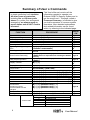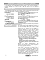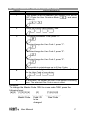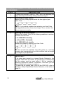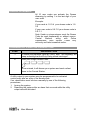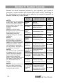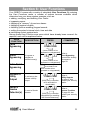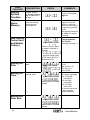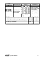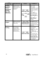
1
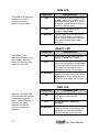
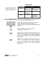
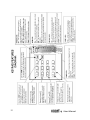
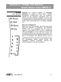
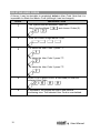
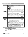
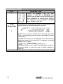
USER MANUAL
VER. B
User Manual
1
Customer Information
1. The ORBIT-6 (Model RP-206 ) complies with FCC Part 68 Rules. On the upper
panel of this product is a label that contains, among other information, the FCC
Registration Number and Ringer Equivalence Number (REN is 0.8B). If requested,
this information must be provided to the Telephone Company.
2. An FCC compliant telephone connector is provided with this equipment. This
equipment is designed to be connected to the telephone network or premises
wiring using a connector, which is Part 68 compliant.
3. If the ORBIT-6 (RP-206 ) is not operating properly, it may cause harm to the
telephone network. If so, the Telephone Company will notify you in advance that a
temporary discontinuance of service may be required. If advance notice is not
practical, you will be notified as soon as possible. Also, you will be advised of your
right to file a complaint with the FCC if it is necessary.
4. The Telephone Company may make changes in its facilities, equipment,
operations, or procedures, which could affect the operation of the equipment. If this
happens, the Telephone Company will provide advance notice in order to enable
you to make the necessary modifications to maintain uninterrupted service. If the
equipment is causing harm to the telephone network, the Telephone Company may
request that the equipment be disconnected until the problem is resolved.
5. Connection to telephone company-provided coin service is prohibited. Connection
to party line service is subject to state tariffs.
6. If trouble is experienced with the ORBIT-6 (RP-206 ), for repair and warranty
information, please contact your supplier.
For service centers please see back cover.
FCC Warning
This equipment has been tested and found to comply with the limits for a Class B
digital device pursuant to Part 15 of the FCC Rules. These limits are designed to
provide reasonable protection against harmful interference in a residential installation.
This equipment generates, uses, and can radiate radio frequency energy and, if not
installed and used in accordance with the instructions, may cause harmful
interference to radio communications. However, there is no guarantee that
interference will not occur in a particular installation. If this equipment does cause
harmful interference to radio or television reception, which can be determined by
turning the equipment off and on, the user is encouraged to try to correct the
interference by one or more of the following measures:
• Reorient or relocate the receiving antenna.
• Increase the separation between the equipment and the receiver.
• Connect the equipment into an outlet on a circuit different from that to which
the receiver is connected.
• Consult the dealer or an experienced Radio/TV technician for help.
Changes or modifications to this unit not expressly approved by Rokonet, Ltd.,
could void the user's authority to operate the equipment.
p/n: 5IN206UM B
2
User Manual
Copyright © 2000
by Rokonet Electronics Ltd.,
14 Hachoma Street
Rishon Letzion 75655
Israel
All rights reserved.
No part of this document may be reproduced in any form without
prior written permission from the publisher.
User Manual
3
Summary of User’s Commands
It is necessary to ARM your system
to obtain protection from intrusion.
All other forms of protection,
including fire and 24-hour panic
alarms (i.e. police, fire, and special
emergency) are always ready to
report alarms and do NOT need to
be armed.
FUNCTION
System Arming
Stay Home Arming
Instant Stay
System Disarming
Duress Disarming
Silencing an Alarm
Bypassing / Unbypassing a
Zone
Quick Bypassing Zone
Reset Smoke Detector(s)
Utility Output Operation
Display Troubles
Display Memory
Setting/Changing
a User Code
Set Date
Set Time
*Set Auto Arm Time
Set Follow-Me Phone No. 1
Set Follow-Me Phone No. 2
**Set Follow-Me Phone No. 3
**Set Follow-Me Phone No. 4
Maintenance:
On/Off Buzzer
On/Off Door Chime
*On/Off Audible Kiss-Off
Indication
This User's Manual contains all the
information needed to operate your
Rokonet ORBIT-6 Security System and to
get the most from it. This page, called a
Command Summary, is intended to give
you brief summaries of common system
operations. More detailed explanations
and related information can be found
within, by referring to the indicated page.
[USER CODE] + [ARM]
[USER CODE] + [STAY]
[STAY] + [STAY]
[USER CODE]
[DURESS CODE]
[USER CODE]
[ Q ] + [ 1] + [USER CODE ] + [ ZONE NUMBER TO BE
BYPASSED / UNBYPASSED]
[ZONE NUMBER TO BE BYPASSED] for at least 2
seconds
[ Q ] + [ 2 ] + [USER CODE ] + [UTILITY OUTPUT
NUMBER which is responsible for resetting the Smoke
Detector]
[ Q ] + [ 2 ] + [USER CODE ] + [ UTILITY OUTPUT
NUMBER ]
4
Page 19
Page 19
Page 19
Page 22
Page 23
Page 22
Page 20,
25
Page 25
Page 25
Page 25
Page 26,
[Q ]+[3]
29
[Q ]+[4]
Page 26
[ Q ] + [ 5 ] + [MASTER CODE] + [CODE NUMBER TO BE Page 17,
26
SET/CHANGED] + [NEW CODE]
[ Q ] + [ 6 ] + [ 1 ] + [MASTER CODE] + [MM] [DD] [YY]
Page 26
[ Q ] + [ 6 ] + [ 2 ] + [MASTER CODE] + [H][H] [M][M]
Page 26
[ Q ] + [ 6 ] + [ 3 ] + [MASTER CODE] + [H][H] [M][M]
Page 26
[ Q ] + [ 7 ] + [ 1 ] + [MASTER CODE] + Phone No. + [#]
Page 27
[ Q ] + [ 7 ] + [ 2 ] + [MASTER CODE] + Phone No. + [#]
Page 27
[ Q ] + [ 7 ] + [ 3 ] + [MASTER CODE] + Phone No. + [ #] Page 27
[ Q ] + [ 7 ] + [ 4 ] + [MASTER CODE] + Phone No. + [ #] Page 27
[ Q ] + [ 8 ] + [MASTER CODE] + [ 1 ]
[ Q ] + [ 8 ] + [MASTER CODE] + [ 2 ]
[ Q ] + [ 8 ] + [MASTER CODE] + [ 3 ]
Get Event From Event Logger [ Q ] + [ 9 ] + [MASTER CODE] + [EVENT NO.]
[ Q ] + [ 0 ] + [MASTER CODE]
Test System
Trouble Table
MORE
ON
PROCEDURE
LED
1
2
3
4
5
Page 28
Page 28
Page 28
Trouble
Low Battery
AC Power Loss
Clock/Date Not Set
Communication Trouble
Bell Loop Trouble
User Manual
Table of Contents
SECTION 1: LET’S GET ACQUAINTED
7
Introduction
7
SOME DEFINITIONS
8
Zone
24-Hour Zone
Day Zone
Central Stations
Chimes
Trouble Reporting
Utility Outputs
Key-switch
8
8
8
8
8
8
8
8
SECTION 2: YOUR KEYPAD
9
Visual Indicators
9
Keys
11
SECTION 3: THINGS YOU SHOULD KNOW
13
ABOUT YOUR ORBIT-6
13
Arming Your System
Full Arming and Home Arming
Quick Arming and Code Arming
Entry/Exit Delays
Arming with the Front Door Open
Sounder Cutoff
The "Squawk" Feature
Follow-Me Feature
Voice Feature
Zone Bypassing
Duress Disarming
Quick Bypassing and Code Bypassing
13
14
14
14
14
14
15
15
15
15
15
15
SECTION 4: OPERATING YOUR SYSTEM
16
Emergency Keys
Police Emergency
Fire Emergency
16
16
16
5
User Manual
Special Emergency
16
User Codes
16
Setting/CHANGING THE MASTER/USER CODES
17
Deleting User Codes
18
ARMING YOUR SYSTEM
19
BYPASSING A ZONE
Disarming an armed system
Silencing an alarm in progress
20
22
22
Duress Disarming
23
SECTION 5: SYSTEM SOUNDS
24
SECTION 6: USER FUNCTIONS
25
Zone Bypassing
Quick Bypassing
Extra Quick Bypassing
Activate a Utility Output
Reset a Smoke Detector(s)
Display System Troubles
Display Alarm Memory
Add, Modify, Delete User and Master Code(s)
Setting the Date
Setting the Time
Set Follow-Me Phone Number 1
Set Follow-Me Phone Number 2
Keypad Sounder/ Chime Operation
Event Logger
System Testing
25
25
25
25
25
26
26
26
26
26
27
27
28
28
28
SECTION 7: SYSTEM TROUBLES
29
6
User Manual
Section 1: Let’s Get Acquainted
INTRODUCTION
Congratulations on your purchase of Rokonet’s
ORBIT-6 Security System. The ORBIT-6 has been
specifically designed to meet a wide range of
security needs for many residential and small
commercial applications.
You communicate with your ORBIT-6 through its
keypad(s). Using its keys, you can issue
commands to your system. In turn, the system can
communicate information to you via its indicators
and by the sounds it makes.
Your ORBIT-6 security system also consists of a
variety of sensors, detectors, and contacts
placed throughout the premises and designed to
recognize abnormal conditions. Typically, your
system protects against intrusion. Some systems
may also have fire protection or environmental
protection (such as gas or water level sensors)
All of your system's detectors, sensors, and
contacts are wired to the control panel. As such,
your system always knows the status of any
protected door, window, hallway, room, or area.
Similarly, it knows if a smoke detector has been
activated.
The control panel, which contains the system's
electronics and backup battery, functions in the
background and, for purposes of security, is
installed out of sight.
User Manual
7
SOME DEFINITIONS
There are a few terms with which you should
become familiar. Knowing them will help you to
better understand and use your system
Zone
A single detector, or group of detectors, usually
relating to a certain area of the premises or type of
protection. Zones that use devices designed to
detect break-ins, are called intrusion zones.
Another kind of zone may contain one or more
Smoke Detectors. Such zones are called fire
zones. An environmental zone typically protects
the premises from gas leaks and/or flooding.
24-Hour Zone
A 24-Hour intrusion zone is always armed and is
usually assigned to openings which should never
be disturbed-like fixed glass and non-movable
skylights.
Day Zone
A Day Zone is one in which a violation during the
disarmed period results only in a keypad
annunciation. However, the same violation during
the armed period will cause a full-fledged alarm.
Central Stations
Besides producing audible alarms at your
premises, it's likely that your system is set up to
Central Station–
continually monitors the activities of many security
systems, usually via the telephone network, and
Chimes
The
is a series of short keypad tones, which
can be set up to annunciate, during the
period, the violation of selected intrusion zone(s).
The chime tone can be used to annunciate the
opens. The chime can be disabled
enabled at
Trouble Reporting
If desired, your security system may also report to
troubles or malfunctions it
Utility Outputs
In addition to your system's normal operation, it's
premises lighting under the control of the ORBIT6—where it can be conveniently turned on and off
from any system keypad, or automatically activated
in response to a system event.
Key-switch
8
Your system may also be equipped with a
keyswitch, useful for simple arming and disarming
operations - usually at a remote location.
User Manual
Section 2: Your Keypad
VISUAL INDICATORS The Orbit-6 can support 6 and 8 zone LED and
LCD keypads. Both of these keypads have the
same operating procedures. This section discusses
the keypad's visual indicators and the use of its
keys.
Each keypad in your
system reports its status
via its LED (lighted)
indicators at the right.
Through its keys, you can
enter commands to "arm"
and "disarm" the system,
bypass intrusion zones,
report emergencies,
silence an alarm in
progress–along with
several other useful
functions.
The four LED indicators found at the upper right
provide typical system indications, as discussed
below and on the next page. Some indicators have
additional functions, explained later on.
POWER LED
The POWER LED is a
useful indicator reflecting
the system's operation.
NOTE: If a trouble
condition exists, the
POWER LED will flash
only when the system is
in its disarmed state.
Once the system is
armed, a previously
flashing POWER LED will
light steadily.
User Manual
CONDITION
(see note at left)
EXPLANATION
ON
The system is operating properly
from commercial (AC) power; its
backup battery is in good
condition.
OFF
The system is inoperative due to
the lack of power (from both
commercial AC and backup
battery); servicing will be required.
FLASHING
Indicates a trouble condition; for
more information on displaying and
attending to trouble conditions, see
pages 29 through 30.
(disarmed
state)
9
ARM LED
The ARM LED indicates
whether or not the
system's intrusion
detectors are armed.
CONDITION
EXPLANATION
ON
The system's intrusion detectors are
armed; subsequent violations of a
protected point or area (e.g. a door,
a window, unauthorized motion) will
result in a burglar alarm.
OFF
The intrusion function of the
system is disarmed.
FLASHING
Occurs when using the emergency
keys on the keypad to send panic,
fire or special emergency alarm and
also when viewing alarms after
disarming.
READY LED
CONDITION
The READY LED
indicates whether or not
the system's intrusion
zones are secured and
ready to be armed.
EXPLANATION
ON
All intrusion zones are secure; the
system is ready to be armed.
OFF
One or more intrusion zones are not
secure and the system is not ready
to be armed; before the system can
be armed, the condition must be
addressed (see pg. 20 through21).
FLASHING
Indicates that one or more of the
system's intrusion zones have been
bypassed; for more information on
bypassing (see pages 20 through
21).
FIRE LED
CONDITION
When lit, the FIRE LED
indicates that the system
is experiencing a fire
alarm. When flashing, a
problem has been
detected on the fire
circuit, and must be
serviced.
10
EXPLANATION
ON
A fire alarm or fire emergency is
in progress or has recently
occurred.
OFF
All fire zones are operating
normally.
FLASHING
A fault has been detected in the
system's fire zone and needs to be
corrected; for more information on
fire zone trouble (see page 29).
User Manual
ZONE LED
CONDITION
The ZONE LEDs indicate
the status of each of the
system’s intrusion zones.
OFF
FLASHING
ON
KEYS
EXPLANATION
SYSTEM DISARMED
The
corresponding
zone is secured.
SYSTEM ARMED
The
corresponding
zone is secured.
The indicated
zone is
not secured.
N/A
N/A
An alarm has
occurred on the
indicated zone.
The keys on the keypad can be used for a variety
of functions. Each is explained below:
Used to input the numeric codes which may be
required for arming, disarming, triggering
emergency alarms, along with several other special
functions.
Used to enter the User Functions mode
(see pages 25 through 27).
Used to arm the system's intrusion detectors to the
"AWAY" mode (see page 13); it may be necessary
to enter a numeric User Code before pressing the
Arm key (see pages 13 and 19 for additional
information).
Used to arm the system's intrusion detectors to the
"STAY" mode (see page 13); it may be necessary
to enter a numeric User Code before pressing the
Stay key (see pages 13 and 19 for additional
information).
User Manual
11
12
User Manual
Section 3: Things You Should
Know About Your ORBIT-6
Arming
Your System
Arming your system enables its intrusion
detectors to trigger an alarm when violated.
Remember, fire protection and the protection
offered by the keypad's emergency keys are
always armed and always available. If your system
is equipped with environmental protection (e.g. gas
and/or water level detection) it is always available
too.
Secured or Bypassed:
Before you arm your system, all of its zones must
either be secured or bypassed. The keypad's
READY LED, if lit, indicates that all zones are
secured. If the READY LED is not lit, a numbered
LED corresponding to the unsecured zone(s) will
be flashing. Before you can arm your system, the
indicated zone(s) must be identified and secured. If
this is not possible, the affected zone(s) can be
bypassed and will be ignored by the system during
the subsequent armed period. Recall that
bypassing, however necessary, reduces the
system's degree of intrusion protection.
User Manual
13
Full Arming and
Home Arming
Quick Arming and
Code Arming
Entry/Exit Delays
Arming with the
Front Door Open
Sounder Cutoff
Panic Button
14
Your ORBIT-6 offers two kinds of system arming.
Full Arming prepares all of the system's intrusion
detectors to sound an alarm, if violated. It is most
often used when the premises will be empty.
Home Arming (or Stay Arming) allows individuals
to remain inside and move about the premises
even after the system is armed. Home Arming
arms the perimeter detectors (e.g. door and
windows), while leaving interior detectors (e.g.
motion detectors) disarmed (bypassed).
Your ORBIT-6 also offers two methods of arming.
Quick Arming achieves the result with just the
press of a single key (either
or
).
Code Arming requires that a valid Master Code or
User Code be entered first. Whether or not your
system permits Quick Arming was determined
during its installation.
Your security system must incorporate an
Entry/Exit Delay to allow proper entry and exit to
and from the premises without causing inadvertent
alarms. A delay period was chosen during your
system's installation to provide suitable time to
allow for your entry and exit.
If set up by your alarm company, the ORBIT-6
allows you the convenience of arming your system
with the front door either closed or open, after
which you must close the door as you leave the
premises before the exit delay period expires. With
such a door open (and all other zones secure), the
system is considered "ready to arm"; the Zone LED
corresponding to the opened door will be lit, as will
your keypad's READY LED.
It's likely that your security system was installed
with a sounding device (e.g. a siren or a bell).
Typically, all sounding devices have cutoffs; that is,
they will shut off after a predetermined interval
(usually several minutes) set by your alarm
company. In many locales, this is required by law.
Once a sounder shuts off, it is still capable of
responding to a subsequent alarm during the same
armed period.
A special panic button can be installed at any
preferred location, to allow immediate and flexible
alarm notification in time of distress.
User Manual
The "Squawk"
Feature
Follow-Me Feature
Voice Feature
Zone Bypassing
Duress Disarming
Quick Bypassing
and
Code Bypassing
A feature known as Bell Squawk is available for
your system. If selected by your alarm company,
the Bell Squawk causes the system's external
sounder (either a siren or a bell) to produce a
momentary "beep" as follows:
One beep: At the conclusion of the Exit Delay,
confirming that the system has been successfully
armed.
Two beeps: Confirming that the system has been
disarmed .
Four beeps: Confirming that the system has been
disarmed after an alarm has occurred.
In case of an alarm event a phone call can be
made to a predefined phone number. There are
three different tone types that represent burglary,
fire and special emergency alarms. The Follow-Me
function can support two phone numbers.
An optional Voice Module can be added to your
system. Up to 3 short messages can be recorded.
These messages replace the alarm tones normally
produced in the follow-me mode.
It may be convenient to have one (or more) of the
zones in your installation bypassed–and thus
ignored by your system.
If you are ever coerced into disarming your system,
you can comply with the intruder's wishes while
sending a silent, duress alarm, to the Central
Station. To do so, you must use a special
Duress Code. Which when used, will disarm the
system in the regular manner, while simultaneously
transmitting a silent alarm to the central station.
Your Orbit-6 offers two methods of Bypassing:
Quick Bypassing achieves the result by pressing
the key number corresponding to the zone to be
bypassed for 2 seconds.
Code Bypassing requires a valid Master Code or
User Code to be entered first.
Whether or not your system permits Quick
Bypassing was determined during its installation.
User Manual
15
Section 4: Operating Your System
In this section, you'll learn how to perform most of the functions needed to
properly operate your ORBIT-6 and to get the most out of your security
system.
EMERGENCY KEYS
Your keypad provides three sets of keys, which can be pushed at any time the
police, fire department, or special emergency is required.
Panic Key
Pressing
and
simultaneously, and
for at least two seconds, will activate a
Panic Key alarm.
Fire Emergency
Pressing
and
simultaneously, and
for at least two seconds, will activate a
Fire Emergency alarm.
Special
Emergency
Pressing
and
simultaneously, and
for at least two seconds, will activate a Special
Emergency alarm.
The annunciation that results during these emergency alarms, along with other
system sounds, is covered in Section 5.
USER CODES
To perform many of the ORBIT-6's functions, a
four-digit security code (often called a User
Code) must be entered at the keypad. In
residential systems, it's likely that all family
members will share the same User Code. In
certain commercial systems, however, it's
common to give each authorized employee
his/her own User Code (discussed on page 17).
Your ORBIT-6 permits up to ten User Codes.
One of the codes is considered the Master
Code; the individual(s) using the Master Code
is given the following special privileges:
• adding, modifying, and deleting User
Codes
• setting the system's internal clock
• performing certain system functions and
tests
Except
for
these
considerations,
the
Master Code and any User Codes assigned to
the system operate identically.
Your ORBIT-6 was given a Master Code of
1–2–3–4 during manufacturing. Unless your
alarm company has already changed it to suit
your preference, it's best to modify this code to
one which is unique and personalized. To
change the Master Code, and/or to set up User
Codes, follow the steps on page 17.
16
User Manual
SETTING/CHANGING THE MASTER/USER CODES
STEP
DESCRIPTION
1
The system must be disarmed (the ARMED LED will be
OFF). Enter the User Functions Mode (
Codes (5):
2
Enter the current 4-digit Master Code:
3
To change the Master Code, press "0":
) and select
To enter/change the User Code 1, press "1":
To enter/change the User Code 2, press "2":
To enter/change the User Code 3, press "3":
It is possible to enter/change up to 9 User Codes.
4
Enter the new 4-digit code selected for the Master Code or
for the User Code of your choice:
5
If successful, the keypad will emit a one-second confirming
tone. The selected User Code is now in effect.
Example:
To change the Master Code 1234 to a new code 7890, press the
following keys:
[Q][5] [1] [2] [3] [4]
[0]
[7] [8] [9] [0]
14243 14243 1442443
Master Code Code I.D.
New Code
to be
changed
User Manual
17
DELETING USER CODES
At times, it may be desirable to completely delete a User Code. Note that it is
impossible to delete the Master Code (although it can be changed).
STEP
1
DESCRIPTION
The system must be disarmed. Enter the
User Functions Mode (
) and choose Codes (5):
2
Enter the current 4-digit Master Code:
3
To delete the User Code 1, press "1":
To delete the User Code 2, press "2":
To delete the User Code 3, press "3":
18
4
Enter 0-0-0-0 (which is NOT a valid code) to clear the
selected User Code.
5
If successful, the keypad will emit a one-second
confirming tone. The selected User Code is now deleted.
User Manual
ARMING YOUR SYSTEM
STEP
1
DESCRIPTION
Check the READY LED on your keypad. If lit or flashing,
the system is READY.
If NOT lit or flashing, the system is NOT ready to be armed.
Secure or bypass the violated zone(s) and then proceed.
Arming when Leaving the Premises Empty:
Away
Arming
.
Enter the four digits of your User Code and press
2
NOTE: If you make a mistake when entering your User
Code, the keypad will produce three short beeps. If so, reenter the above sequence correctly.
If your system has Quick Arming, simply press
Leave the premises and close the door. The keypad will
beep as counts down the Exit Delay period.
3
Arming with the Premises Occupied
Enter the four digits of your User Code and press
Stay
Arming
2
.
NOTE: If you make a mistake when entering your User
Code, the keypad will produce three short beeps. If so, reenter the above sequence correctly.
If your system has Quick Arming, simply press
.
If required, leave the premises and close the door. The
keypad will beep as it counts down the Exit Delay period.
The internal zones will be automatically bypassed.
3
Note: By pressing
(twice) the system will silence the beeps on
the keypad and cancel the entry delay time.
By pressing
keypad.
User Manual
during exit time will silence the beeps on the
19
BYPASSING A ZONE
STEP
1
Code
Bypassing
DESCRIPTION
Check the READY LED on your
keypad. If NOT lit or flashing, the
system has at least one faulted intrusion
zone identified by noting which LED(s)
are flashing in the keypad's ZONES
area, shown at the left.
To bypass such a zone(s) and cause it to be ignored by the
system, enter the following sequence correctly:
2
NOTE: If you make a mistake when entering your User
Code, the keypad will produce three short beeps. Re-enter
if necessary.
An additional zone(s) can be bypassed at the same time by
adding its number to the sequence. For example, to bypass
Zones 2 and 3, press:
[
] + [ 1 ] + [USER CODE] + [ 2 ] + [ 3 ]
The same sequence can “toggle” the bypass(es) during the
disarmed period so that they may be either applied or
removed.
Press # or Q to approve or wait 2 seconds (timeout period).
20
User Manual
BYPASSING A ZONE (CONT.)
If the system is programmed for quick bypass the following
option is available:
Quick
Bypass
To bypass a zone simply press the corresponding keypad
number for at least 2 seconds.
2
An additional zone(s) can be bypassed at the same time by
adding its number to the sequence. For example, to bypass
Zones 2 and 3, press:
[ 2 ] for 2 seconds + [ 3 ]
The same sequence can “toggle” the bypass(es) during the
disarmed period so that they may be either applied or
removed.
3
The READY LED, when flashing, indicates that there is one
or more bypassed zones. Any zone(s) bypassed during the
disarmed period will remain bypased when the system is
armed.
Zone(s) that are bypassed, during the time the system is
armed, will automatically be restored to its normal,
unbypassed condition, when the system is disarmed.
DETERMINING WHICH ZONE(S) IS BYPASSED
STEP
1
2
DESCRIPTION
The system must be
disarmed. If the keypad’s
READY LED is flashing,
there is at least one
bypassed zone, in the
If quick bypass is enabled in your
system. To determine
system, simply press:
which zone is bypassed,
follow this sequence:
Observe the keypad’s ZONES area. LED(s) corresponding to the
bypassed zone(s) will light for several seconds.
User Manual
21
DISARMING AN ARMED SYSTEM AND/OR SILENCING AN ALARM
IN PROGRESS
STEP
DESCRIPTION
1
If outside the premises, open an "entry" door; the keypad(s) will
beep indicating that the Entry Delay period has begun.
Disarming an armed system
Before the Entry Delay expires, enter the four digits of your
User Code.
2
NOTE: If you make a mistake when entering your User Code,
the keypad will produce three short beeps. If so, re-enter the
above sequence correctly.
2
Silencing an alarm in progress
Observe the keypad. If any of the following conditions is evident,
an alarm has occurred:
·• the ARM LED is flashing
·• a Zone LED is lit steadily
·• the FIRE LED is lit steadily
Disarm the system by entering your User Code:
It's best to enter the premises only after police or a security
company has investigated and you feel confident that the burglar
is no longer on your premises.
3
22
IMPORTANT!
If the alarm was caused by a tripped Smoke Detector(s), the
keypad's FIRE LED will remain lit—providing an indication that
the fire system must be reset before it will be capable of
detecting subsequent alarms. Furthermore, until reset, you will
be prevented from arming your system.
To reset the fire system and to turn off the FIRE LED, refer to
Activate a Utility Output/Reset Smoke Detectors, in the table on
page 25.
User Manual
DURESS DISARMING
All 10 user codes can activate the Duress
disarming by adding 1 to the last digit of your
user code.
Example:
if your code is 1-2-3-4 your duress code is 1-23-5
If your user code is 5-6-7-0 your duress code is
5-6-7-1
Note: Under no circumstances must the Duress
Code be used haphazardly or without reason.
Central
Stations,
along
with
Police
Departments, treat Duress Codes very
seriously and take immediate action.
DISARMING BY USING THE DURESS CODE
STEP
1
2
DESCRIPTION
If outside the premises, open an "entry" door. The keypad(s) will
beep indicating that the Entry Delay period has begun.
Enter your 4-digit Duress Code:
Once entered, it will disarm your system and send a silent
alarm to the Central Station.
A utility output in your system may be programmed to be activated
continuously after an entry of the duress code.
If so, deactivation must be done manually by one of the following
procedures:
1. Arming the system.
2. Disarming the system after an alarm that occurred while the utility
output was still activated.
User Manual
23
Section 5: System Sounds
Besides the visual indications provided by your keypad(s), your system is
designed to produce audible annunciation after certain events. Depending on
the circumstance, such sounds may be made by your system's keypad(s), its
external sounder (e.g. a siren or bell),
EVENT
NOTE 1:
If selected during the installation,
a brief "chirp" may be heard from Intrusion
Alarm
the siren when the Exit Delay
period expires. See page 14 for
additional information.
Fire Alarm
NOTE 2:
Whether or not the Police
Emergency alarm is annunciated
by the external sounder is
determined by the alarm
company during your system's
installation.
NOTE 3:
Keypad beeps in response to
Entry/Exit Delay countdowns,
Keypad Fire Emergencies, and
keypad errors and confirmations
are typically enabled. At the
user's discretion, such beeps
may be disabled. See page 14
for additional information.
NOTE 4:
Any intrusion zone, if selected for
the chime feature, will, when
violated during the disarmed
period, cause the keypad to
annunciate the event (see
page 8). Through User Functions
(see page 27), the chime can
also be disabled when not
desired.
NOTE 5:
Based on decisions made at the
time your alarm system was
installed, keypad(s) may beep
during this type of alarm.
KEYPAD SOUND
SIREN/
BELL
YES
MAYBE
(see Note 5)
(continuous)
Rapidly repeating
tones (see Note 3)
(staggered)
YES
Keypad
Police
Emergency
A momentary chirp
Keypad Fire
Emergency
Rapidly repeating
tones (see Note 3)
Keypad
Special
Emergency
A momentary chirp
no sound
Arming or
disarming
A one second tone if
completed correctly;
three rapid error beeps
if incorrect (see Note 3)
no sound
Entering an
incorrect key
sequence
Entry Delay
countdown
OPTIONAL
(see Note 2)
YES
Three rapid beeps
no sound
(see Note 3)
Slowly repeating tones
until the entry delay
period expires (see Note
no sound
3)
Exit Delay
countdown
Slowly repeating tones
OPTIONAL
until the exit delay
period expires (see Note (see Note 1)
3)
Entering data
into the User
Functions
mode
A one second tone if
completed correctly;
three rapid error beeps
if incorrect (see Note 3)
no sound
(see page 25)
24
User Manual
0
Section 6: User Functions
Your ORBIT-6 comes with a variety of selectable User Functions. By entering
the User Functions mode, a number of options become available which
determine how your alarm system operates, such as:
• adding, modifying, and deleting User Codes
• bypassing zones
• displaying a "memory" of previous alarms
• displaying system troubles
• disabling (and re-enabling) keypad sounds
• setting the system's internal clock, time and date
• performing certain system tests
Among these User Functions are some which have already been covered. As
required, each will be explained below.
USER
DESCRIPTION
PRESS
COMMENTS
FUNCTION
Zone
Bypassing
+
+ USER CODE
+
(zone number to be
bypassed or unbypassed)
Quick
Bypassing
To bypass or
unbypass a
selected zone(s)
Extra Quick
Bypassing
Activate a
Utility
Output
Reset a
Smoke
Detector(s)
+
+
(zone number to be
bypassed or unbypassed)
Refer to
Zone Bypassing
procedures, already
discussed on
page 20.
for at least 2 sec.
(zone number to be
bypassed or unbypassed)
To activate or deactivate a Utility
Output
To reset a Smoke
Detector
+
+ USER CODE
+
(Utility Output number
to be activated or
deactivated)
+
+ USER CODE
+
(Utility Output number
responsible for resetting
the Smoke Detector(s)
User Manual
Refer to
Utility Outputs
on page 8; also
consult your security
dealer.
Refer to
System Troubles
on page 29; also
consult your security
dealer.
25
USER
FUNCTION
Display
System
Troubles
Display
Alarm
Memory
DESCRIPTION
PRESS
Display system
problem(s) causing
the POWER LED
to flash
+
Reviews any
alarms occurring
during the last
armed period
+
Add, Modify,
Delete User
and Master
Code(s)
+
+ MASTER CODE
+
COMMENTS
Refer to
System Troubles on
page 29.
Via its LEDs, the
keypad reveals the
zone(s) in which an
alarm occurred during
the previously-armed
period.
After several seconds,
the LEDs will restore
to normal.
Refer to Setting /
Changing Master /
User Codes,
discussed on page 17.
(number of the Code to
be added, modified, or
deleted)
+
(the new 4-digit code)
NOTE: Use 0-0-0-0 to
delete the Code.
Setting the
Date
Set the systems
date
Setting the
Time
Sets the system’s
internal clock
+
+ MASTER CODE
D
+
+ D
+ Y
Y
+
+ MASTER CODE
+
enter time in HH:MM
format
Setting the
Auto Arm
+
To enter date as: MM
DD YY
MM: month 1-12
DD: Day 1-31
Year: 00-99
Use 24-Hour format,
as in these examples:
• for 12:30 AM,
enter 0030
• for 8:45 AM,
enter 0845
• for 6:15 PM,
enter 1815
the clock must be set
to insure proper
system operation.
Use 24-Hour format.
+ MASTER CODE
+
enter time in HH:MM
format
26
User Manual
USER
FUNCTION
DESCRIPTION
PRESS
or
Set FollowMe Phone
Number 1- 4
Sets the first phone
number for the
follow-me function
(up to 24 digits)
or
or
COMMENTS
+
Enter the phone
number in the same
manner as MS number
during installation.
+
+
+
+ MASTER CODE
+ Phone Number
+ [#]
FUNCTION
stop dialing and wait for a new dial tone
wait a fixed period before continuing
switch from Pulse to Tone (or from Tone to Pulse)
* If required, include
the following special
functions to achieve
the effect listed in the
table:
SEQUENCE
[STAY], [1]
[STAY], [2]
[STAY], [3]
RESULTS
A
B
C
send the DTMF Q character
[STAY], [*]
*
send the DTMF # character
[STAY], [#]
#
User Manual
27
USER
FUNCTION
DESCRIPTION
Keypad
Sounder/
Chime
Operation/
Audible
Kiss-Off
Indication
Determines how the
keypad's internal
sounder will operate
under specific
conditions
Event
Logger
Retrieves events
located in the event
logger memory (up
to 99 events).
System
Testing
Provides a brief test
of the following:
·• keypad LEDs
·• keypad sounder
·• external siren
·• standby battery
28
PRESS
COMMENTS
After entering the
Master Code,
press
to
enable/disable current
operation of keypad's
+
beeps (see Note 3 on
+ MASTER CODE page 24) .
Press
to
disable/enable the
+ / OR
"chime" for intrusion
zones having this
+ / OR
feature (see page 8).
Press
to
disable/enable the
Audible Kiss-Off
Indication.
The event number is
represented by the
+
LEDs (events are
+ MASTER CODE zone
presented from the
+ Event Number last entered to the first
registered).
The external sounder
will be activated
momentarily.
• The keypad's LEDs
will flash.
• If enabled, the
+
keypad's sounder will
beep.
+ MASTER CODE • A low battery (see
pages 8 and 29) or a
loss of commercial
power will cause the
POWER LED to flash;
if so, consult your
security dealer.
User Manual
Section 7: System Troubles
Your ORBIT-6 is designed to report any troubles or malfunctions it may detect.
Notification that a problem exists is made to the user, through indications on
the keypad(s) and, in many cases, to the Central Station and to your dealer.
Any incidence of trouble should be taken seriously and acted upon
immediately. If not remedied quickly, a trouble condition will likely compromise
your system and prevent it from properly doing its job.
The ORBIT-6 is designed to be as trouble-free as possible. Were a problem to
develop, the POWER LED will flash about once every second. If so, to
determine the problem, perform the sequence on the following page.
In certain cases, the keypad's FIRE LED may remain lit steadily, even though
there is no alarm in progress and the system is disarmed. Refer to the
explanation and remedy below:
USER FUNCTION
DESCRIPTION AND REMEDY
After a fire alarm has occurred and been silenced, the
keypad's red FIRE LED will remain lit steadily if a Smoke
Detector (presumably the one which caused the alarm)
remains tripped. Until reset, a tripped Smoke Detector will
prevent the READY LED from being lit, and will NOT permit
the system to be armed.
the FIRE LED
To reset a tripped Smoke detector and to extinguish the red
remains lit
FIRE LED, follow this procedure, which is typical:
+
+ USER CODE
+
64444744448
UTILITY OUTPUT NUMBER
(which is responsible for resetting the Smoke Detector)
Consult your security dealer for alternate information on
resetting smoke detectors, if applicable.
Once done, the READY LED will indicate the system's
status and you will be able to arm your system.
User Manual
29
IDENTIFYING SYSTEM TROUBLES
STEP
DESCRIPTION
1
Perform if the POWER LED is flashing. If lit steadily, there
are no system troubles. To view trouble conditions, the
system must be disarmed. Enter the User Functions Mode
by pressing [
] and then select View Troubles (3):
2
The keypad will beep and its LEDs will light, reflecting the
information below. After several seconds, the display will
return to normal.
3
FLASHING:
Trouble Detected
OFF:
(normal in this mode)
OFF:
(normal in this mode)
IF ON:
Fire Zone Trouble
(contact your dealer)
IF ON:
IF ON:
Low Battery (contact dealer)
AC Power Loss (see Note 1)
IF ON:
Clock, Time & Date Not Set
(see page 19)
Communications Trouble
(see Note 2)
Bell Loop Trouble
(see Note 3)
IF ON:
IF ON:
In an 8 zone keypad there are 2 more LEDs which are only zone indicators
and not system indicators.
NOTE 1: Check that the ORBIT-6's Plug-In Transformer has not been
removed from its outlet. If intact, check that a blown fuse, a switch, or a
tripped circuit breaker has not interrupted the circuit supplying power to
the transformer.
NOTE 2: The ORBIT-6 has failed in its attempts to report an alarm or
trouble condition to the Central Station. Check that your telephone line is
functioning. Check to see if your external bell has been tampered with. If the
problem still exists contact your dealer.
NOTE 3: The ORBIT-6 has failed in its attempt to identify the Bell Loop.
It is possible for more than one trouble to be present at the same time.
If so, multiple Zone LEDs will be lit simultaneously.
30
User Manual
EMERGENCY EVACUATION PLANS
An emergency evacuation plan should be established and used during an
actual fire alarm condition. The following steps are recommended by the
National Fire Protection Association (NFPA) and can be used as a guide
when establishing a similar plan for your circumstances.
1. Draw a floor plan of your premises showing windows, doors, stairs,
and rooftops, which can be used for escape. An example has been
provided below.
2. Indicate each occupant's escape routes by determining two means of
flight from each room. One should be the normal exit from the
building, while the other may be a window that opens easily, or
another alternate route. An escape ladder may have to be located
near an escape window if there is a long drop to the ground below.
Always keep escape routes free from obstruction.
3. Practice escape procedures and set a meeting place outdoors for a
headcount of the building's occupants.
4. In a home, sleep with the bedroom door closed to increase your
escape time. If a fire is suspected, first test the door for heat. If you
think it is safe, brace your shoulder against the door and open it
cautiously. Be ready to slam the door if smoke and heat rush in.
5. After escaping from a fire, call the Fire Department from a neighbor's
phone.
After the installation of your
Security System has been completed,
notify your local Fire and Police
Departments to give them your name
and address for their records. Early
warning fire detection is best
achieved by the installation of fire
detection devices in all rooms. This
equipment should be installed in
accordance with the National Fire
Protection Association's Standard 72.
For additional information, write to the
National Fire Protection Association
(NFPA) at Batterymarch Park,
Quincy, MA 02289.
User Manual
31
Notes
32
User Manual