1
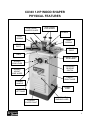
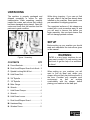
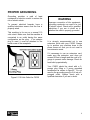
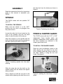
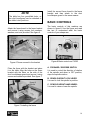
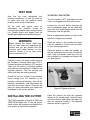
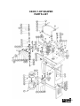
CX303 1-HP WOOD SHAPER USER MANUAL TABLE OF CONTENTS General Safety Instructions..................................................................................... 3 Specific Safety Instructions..................................................................................... 4 CX303 Features...................................................................................................... 5 Physical Features ................................................................................................... 6 Un-Packing ............................................................................................................. 7 Set Up..................................................................................................................... 7 Proper Grounding ................................................................................................... 8 Assembly ................................................................................................................ 9 Spindle.................................................................................................................... 9 Fence & Shaper Guard ........................................................................................... 9 Basic Controls.........................................................................................................10 Test Run ................................................................................................................. 11 Installing the Cutter ................................................................................................. 11 Connecting to a Dust Collector ............................................................................... 12 Table Insert ............................................................................................................. 12 Forward/Reverse Switch......................................................................................... 12 Hold Down Clamps ................................................................................................. 13 Fence Adjustment ................................................................................................... 13 Speed Change ........................................................................................................14 Belt Replacement.................................................................................................... 15 Belt Tensioning .......................................................................................................15 Shaping With the Fence.......................................................................................... 15 Free Hand Shaping................................................................................................. 16 Using Collars .......................................................................................................... 17 Maintenance ........................................................................................................... 18 Lubrication .............................................................................................................. 18 Cleaning.................................................................................................................. 18 V-Belt Inspection..................................................................................................... 18 Troubleshooting ...................................................................................................... 19 Wiring Diagram ....................................................................................................... 20 Parts Breakdown & List.......................................................................................21-22 Warranty ................................................................................................................. 23 2 GENERAL SAFETY INSTRUCTIONS FOR MACHINES Extreme caution should be used when operating all power tools. Know your power tool, be familiar with its operation, read through the user manual and practice safe usage procedures at all times. ALWAYS read and understand the user manual before operating the machine. CONNECT your machine ONLY to the matched and specific power source. ALWAYS wear safety glasses respirators, hearing protection and safety shoes, when operating your machine. DO NOT wear loose clothing or jewelry when operating your machine. A SAFE ENVIRONMENT is important. Keep the area free of dust, dirt and other debris in the immediate vicinity of your machine. BE ALERT! DO NOT use prescription or other drugs that may affect your ability or judgment to safely use your machine. DISCONNECT the power source when changing drill bits, hollow chisels, router bits, shaper heads, blades, knives or making other adjustments or repairs. NEVER leave a tool unattended while it is in operation. NEVER reach over the table when the tool is in operation. ALWAYS keep blades, knives and bits sharpened and properly aligned. ALL OPERATIONS MUST BE performed with the guards in place to ensure safety. ALWAYS use push sticks and feather boards to safely feed your work through the machine and clamp the work-piece (when necessary) to prevent the workpiece from any unexpected movement. ALWAYS make sure that any tools used for adjustments are removed before operating the machine. ALWAYS keep the bystanders safely away while the machine is in operation. NEVER attempt to remove jammed cutoff pieces until the saw blade has come to a full stop. 3 CX303 – 1HP WOOD SHAPER SPECIFIC SAFETY INSTRUCTIONS Read and follow all the instructions and safety precautions in the user manual before setup or use. For the protection of your eyes, always wear safety glasses, goggles or face shield while operating the shaper. Never place your fingers or hands in the line of cut. If you slip, your hands or fingers may come into contact with the cutter. Always use a push stick when feeding stock against the cutter. Make sure the keyed washer is mounted directly under the spindle nuts. All guards must be in place while operating the shaper to ensure safety. Always feed the stock smoothly against the rotation of the cutter. Do not force the machine. It will perform a better job at a rate for which it is designed. Allow the motor to reach the full speed before feeding stock against the cutter. Use the overhead guard when adjustable fence is not in place. Make sure before making any adjustments, the switch is in the “OFF” position and the cord is un-plugged. Never leave the shaper unattended while it is running. Always use the cutters designed to be used with CX303 and similar shapers. Do not expose the shaper to rain or use in damp locations. Clean and sharp tools give safer and better performance. Dull cutters can cause kick backs and excessive chatter. Always check the cutter and other parts for proper adjustment before cutting operation. Always make sure that your shaper is in a stable position. Cutting heavy, long stock may alter the stability of the shaper. In the event that this may occur, the shaper should be firmly bolted to the floor. Do not wear loose clothing, neckties, jewelry or gloves that can get caught in moving parts. Confine long hair and keep sleeves above the elbow. Always use a feather board and/or holddowns to support your work-piece when necessary. Make sure you have read and understood all the safety instructions in the manual and you are familiar with your shaper, before operating it. If you fail to do so, serious injury could occur. WARNING! The safety instructions given above can not be complete because the environment in every shop is different. Always consider safety first as it applies to your individual working conditions. 4 CX303 – 1HP WOOD SHAPER FEATURES MODEL CX303 – 1-HP WOOD SHAPER As part of the growing line of Craftex woodworking equipment, we are proud to offer the CX303 a 1-HP Wood Shaper. The Craftex name guarantees Craft Excellence. By following the instructions and procedures laid out in this user manual, you will receive years of excellent service and satisfaction. The CX303 is a professional tool and like all power tools, proper care and safety procedures should be adhered to. Motor .............................................. 1-HP, 110-V, 60Hz, Single Phase, 14-Amps RPM ...............................................3450 RPM Table Size....................................... 20-1/4” x 17-3/4” Spindle Travel................................. 3” Spindle Size....................................1/2” and 3/4" Spindle Speeds .............................. 7000 and 10000 RPM Direction ......................................... Forward / Reverse Table Opening Diameter ................ 3” Fences............................................Two Individually Adjustable Wooden Fences Fences Size.................................... 9-1/2” x 2-3/4” Dust Port......................................... One 3” Floor to Table Height ...................... 33” Weight ............................................ 100 Kg Warranty ......................................... 3 Years 5 CX303 1-HP WOOD SHAPER PHYSICAL FEATURES DUST HOOD/ SHAPER GUARD DUST HOOD LOCK KNOBS SPINDLE HOLD DOWNS HOLD DOWNS FENCE PIECE FENCE PIECE TABLE CABINET DOOR LOCK KNOB SPINDLE LOCK LEVER FORWARD/ REVERSE SWITCH SPINDLE HEIGHT HAND WHEEL CABINET RIGHT DOOR CABINET HANDLE CABINET LEFT DOOR POWDER COATED PAINT POWER CORD NAME PLATE & WARNING LABEL 6 UNPACKING The machine is properly packaged and shipped completely in crates for safe transportation. When unpacking, carefully inspect the crates and ensure that nothing has been damaged during transit. Open the crates and check that the machine and the parts are in good condition. While doing inventory, if you can not find any part, check if the part has already been installed on the machine. Some parts come pre-assembled for shipping purposes. The unpainted surfaces of this shaper are coated with a rust preventive waxy oil and you will want to remove this before you begin assembly. Use a solvent cleaner that will not damage painted surfaces. SETUP Before setting up your machine you should read and understand the instructions given in this manual. WARNING Figure-1 Inventory CONTENTS QTY A. Fence Brackets .................................. 2 CX303 is a very heavy machine, do not over-exert yourself. For safe moving use fork truck or get the help of an assistant or friend. B. Dust Hood/Shaper Guard Lock Knob . 2 C. Spindle Locking Bolt & Nut................. 1 D. Hold Down Rod .................................. 2 E. 3/4” Spindle ........................................ 1 F. 1/2" Spindle ........................................ 1 G. Miter Gauge ....................................... 1 When setting up your machine, you will want to find an ideal spot where your shaper will most likely be positioned most of the time. Consider your complete work environment as well as working comfortability with the shaper, before placing your machine in the ideal spot. H. Wrench............................................... 1 I. Hold Down Clamps..............................4 J. Wrench................................................1 K. Hold Down Levers ...............................4 L. Dust Hood/Shaper Guard....................1 M. Hardware Bag .....................................1 N. Wooden Fence....................................2 7 PROPER GROUNDING Grounding provides a path of least resistance for electric current to reduce the risk of electric shock. To prevent electrical hazards, have a qualified electrician ensure that the line is properly wired. This machine is for use on a normal 110 volts circuit. Make sure that the machine is connected to an outlet having the same configuration as the plug. If an adaptor plug is used, it must be attached to the metal screw of the receptacle. WARNING Improper connection of the equipmentgrounding conductor can result in a risk of electric shock. Check with a qualified electrician if you are in doubt as to whether the outlet is properly grounded. It is strongly recommended not to use extension cords with your CX303. Always try to position your machine close to the power source so that you do not need to use extension cords. If it necessary to use an extension cord, make sure the extension cord does not exceed 50-feet in length and the cord is 14gauge to prevent motor damage. Check for heat build up periodically. Figure-2 110-Volts Outlet for CX303 Your CX303 should be wired with a 3prongs plug fitting a 3 prong grounded receptacles as shown in figure-2. Do not remove the grounding prong to fit it into a 2pronged outlet. Always check with a qualified electrician if you are in doubt. 8 ASSEMBLY the draw bar from the bottom as shown in figure-4. Read the manual and follow the instructions given in this manual to assemble your CX303. SPINDLE The CX303 comes with two spindles 3/4" and 1/2". TO INSTALL THE SPINDLE: Make sure the switch is in the “OFF” position and the cord is un-plugged from the power source. Loosen the arbor lock lever located on the front of the machine and turn the hand wheel to raise the arbor all the way up. Align the keyways on the spindle with the keys on the arbor and Insert the spindle into the arbor opening as shown in figure-3. Figure-4 Tightening the draw bar FENCE & SHAPER GUARD The CX303 comes with two 9-1/2” x 2-3/4” independent fence boards which are attached independent fence brackets and the fence brackets are attached to the shaper guard/ dust hood. TO INSTALL THE SHAPER GUARD: Place the dust hood/shaper guard on the table aligning the two holes on the dust hood / shaper guard with the two holes on the table. Secure it using the two lock knobs. See figure-5. Figure-3 Inserting spindle into the arbor opening Slide the draw bar into the shaft on the spindle pulley from the bottom and tighten with your hand. Use a wrench to hold the top part of the spindle while tightening the draw bar nut on Figure-5 Installing the dust hood / shaper guard 9 NOTE The table has four pre-drilled holes, so the dust hood/guard can be attached to the table in two positions. Install the second fence board to the fence bracket and then attach to the dust hood/shaper guard in the same manner. BASIC CONTROLS Attach the fence board to the fence bracket and secure it using screws, lock washers, washers, and nuts provided. See figure-6. The basic controls of this machine are shown in figure-8. Use the figure and read the text to understand what the basic controls of your shaper are. Figure-6 Fence secured to the bracket Figure-8 Basic controls on CX303 Place the fence with the bracket and place it on the table. Align the holes on the fence bracket with the holes on the side of the dust hood/shaper guard and secure it using screws and washers provided. See figure-7. A. FORWARD / REVERSE SWITCH It is used to control the direction of rotation of the spindle and when in OFF position, stops the spindle rotation. B. SPINDLE HEIGHT LOCK LEVER It is used to lock the spindle in position. C. SPINDLE HEIGHT HAND WHEEL It is used to raise or lower the spindle. Figure-7 Installing the fence 10 TEST RUN Now that you have assembled your machine completely, it is time for a test run to make sure that the machine works properly and is ready for operation. All the tools and objects used for assembling the machine should be removed and cleared away during the test run. Double check and ensure that the spindle and drawbar are installed properly. WARNING Before starting the shaper, make sure that you have read and understood the manual and you are familiar with the functions and safety features on this machine. Failure to do so may cause serious personal injury. Plug the cord to the power outlet and turn the Forward / Reverse switch from OFF to Forward position and back to OFF position. Then turn the switch to Reverse position and make sure the spindle is rotating in the opposite direction. Test the controls and make sure they are working properly. During the test run if there is any unusual noise coming from the machine or the machine vibrates excessively, shut off the machine immediately and disconnect the cord from the power source. Check all the parts you have assembled once again and investigate to find out the problem. INSTALLING THE CUTTER The CX303 operates at speeds of 7000 and 10000 RPM. Make sure to use the proper sized cutters with proper sized spindles on your shaper to ensure safe operation. TO INSTALL THE CUTTER: Turn the machine “OFF” and make sure the cord is un-plugged from the power source. Loosen the two lock knobs securing the dust hood/shaper guard on the table and move the dust hood/shaper guard and the fence away from the spindle. Place an appropriate spacer or collar on the spindle for support (as needed). Place the cutter on the spindle and make sure the orientation of the cutter is correct for your cutting application. Place the spacer or collar (as needed) on the top and thread the nut onto the spindle shaft. Hold the spindle shaft from the top with a wrench for leverage and tighten the nut. See figure-9. Figure-9 Tightening the nut Place the second nut with the opposite thread on the spindle shaft. Hold the lower nut with a wrench and tighten the upper nut with the opposite thread in the opposite direction shown in figure-10. 11 TABLE INSERT CX303 comes with two different size table inserts to be used with different size cutters. Clean any dust or dirt on the spindle opening edges before installing the table insert. Place the table insert in the spindle opening, and make sure the insert is flush with the table surface. See figure-11. Figure-10 Tightening the upper nut CONNECTING TO A DUST COLLECTOR CX303 features a 3” diameter dust port to connect to a dust collector. When connecting to a dust collector, use a proper sized hose and make sure all the connections are sealed tightly. It is recommended to use a proper sized dust collector with the CX303 to ensure adequate dust collection. Figure-11 Installing the table insert FORWARD/REVERSE SWITCH The CX301 is equipped with a Forward / Reverse switch which controls the direction of rotation of the spindle. Figure-12 Dust port on CX303 WARNING Always use grounding wire to prevent fire or explosion. Figure-13 Forward / Reverse switch 12 Most of the jobs are done with the forward rotation of the cutter but some times if it is necessary, you will want to flip the cutter on the spindle and reverse the cutter rotation to perform some specific jobs. Loosen the screws and knobs on the clamps and slide the hold down levers through the clamps. Once the levers are in position, tighten the knobs and screws. See figure-14. The selector knob on the switch can be turned and set on any of the three positions; Forward, Off and Reverse. When the switch is in “Forward” position, the spindle will rotate in counter-clockwise direction and when in “Reverse” position, the spindle will rotate in clockwise direction. When the switch is set on “Off”, the spindle will stop moving. WARNING Before operating the shaper, check the direction of the rotation of the cutter. Cutters rotating backwards can cause unsafe conditions. HOLD DOWN CLAMPS The CX303 comes with four hold down clamps holding the work-piece on the table and against the fence while operation. Make sure to the hold down clamps while shaping, to prevent the work-piece from flying away from the cutter. Figure-14 Installing the hold downs FENCE ADJUSTMENT The CX303 features two independent fence boards mounted to the fence brackets. The fence brackets are attached to the dust hood/shaper guard assembly. The fence assembly is adjusted forward or backward on the table by loosening the screw securing the fence bracket to the dust hood/shaper guard and turning the fence adjustment knob shown in figure-15. TO INSTALL THE HOLD DOWN CLAMPS: Slide one hold down clamp on each end of the rod. Insert the long end of the rod through the hole on the fence bracket and hand tighten the screw securing the rod in position as shown in figure-14. Figure-15 Fence adjustment knob 13 The left and right independent fence boards have four holes on each, allowing the fence boards to be repositioned as needed. Figure-17 Loosening the screw Figure-16 Fence halves installed farther from each other allowing larger cutters SPEED CHANGE The CX303 is a two-speed shaper and operates at 7000 and 10000 RPM. Once the screw is loosened, pull the motor towards the spindle pulley and change the belt position on the spindle pulley. The spindle pulley has two grooves for the belt to be positioned. Look at figure-18 and position the belt on one of the spindle pulley grooves for the required RPM. TO CHANGE THE SPEED: Turn the switch to “OFF” position and make sure the cord is un-plugged from the power source. Loosen the lock knob and open the cabinet door. Loosen the spindle height lock lever. Turn the spindle height hand wheel to lower the spindle and motor assembly. Loosen the screw securing the motor bracket (shown in figure-17). This will loosen the tension on the belt. Figure-18 Belt position on the spindle pulley for 7000 RPM and 10000 RPM Pulling away the motor from the spindle pulley will apply tension on the belt. Lock the motor in position as shown in figure-17 and re-install the cabinet door. 14 BELT REPLACEMENT The belt stretches with use and should be checked regularly and replaced if needed. To change the drive-belt on your CX303: Turn the switch “OFF” and make sure the cord is un-plugged from the power source. Open the cabinet door and release the belt tension by loosening the screw shown in figure-19. SHAPING WITH THE FENCE Using the fence is the safest method of shaping. Most operations that use the fence for support can be performed by following the guidelines below: If performing a cut where a portion of the edge of the work-piece is not touched by the cutter-head, both sides of the fence are positioned at the same depth. See figure20. Figure-20 Fences at the same depth Figure-19 Loosening the screw Take the belt off the pulleys and replace with a new one. BELT TENSIONING When performing a cut where the entire edge of the work-piece is removed, the fence must be positioned differently. If the fence halves are kept in line, once the work-piece passes through the cutter-head, the shaped edge would no longer be supported against the fence. See figure-21. Once the new belt is installed, push the motor away from the spindle pulley and retighten the screw shown on page-19. The belt should be tensioned enough to prevent slippage while operation. Figure-21 Work-piece not supported with the out-feed fence 15 To prevent this, the out-feed fence must be repositioned to compensate for the material being removed. Advance the out-feed side of the fence equal to the amount of material being removed. Figure-23 Starting pin (Not Provided) Figure-22 Out-feed fence positioned forward equal to the depth of cut If using a miter gauge, the in-feed side of the fence must be parallel with the miter slot. Also make sure that the other fence piece is positioned out of the way so that it does not contact the work-piece after it passes through the cutter-head. Use a hold down jig or push blocks for the safety of your hands and place the workpiece against the starting pin. Plug the cord into the receptacle and turn the machine “ON”. Slowly pivot and feed the work-piece into the cutter and try to avoid starting your cut on the corner of the work-piece to avoid kick back. FREE HAND SHAPING To set up the shaper for free hand shaping: Turn the switch “OFF” and make sure the cord is un-plugged from the power source. Remove the fence assembly and insert the starting pin (Not Provided) in the most suitable hole on the insert. See figure-23. WARNING When performing free hand shaping, the fence is removed which exposes the cutter and increase the risk of injury. 16 USING COLLARS When shaping work-pieces that have irregular shapes, it is necessary to use rubcollars. Collars can be used below or above the cutter or between two cutters. Each setup type has its own advantages and disadvantages. BELOW THE CUTTER When using rub-collars below the cutter, the user will have a good view of the cut. But if the work-piece is lifted even slightly, it will cause the cutter to gouge the wood and ruin the work-piece. Figure-35 Using collar above the cutter BETWEEN THE CUTTERS A collar is used between two cutters when both edges of the work-piece are to be shaped. Like using the collar below the cutter, this method has also the disadvantage that if the work-piece is accidentally lifted up, the cutter will gouge and ruin the work-piece. Figure-24 Using collars below the cutter ABOVE THE CUTTER When using collars above the cutter as shown in figure-25, the cut will not be affected by slight variations in the thickness of the work-piece and the work-piece will not be gouged if lifted up accidentally. Figure-26 Using collar between the cutters The only disadvantage of using a collar above the cutter is that the operator will not be able to see the cut being made. 17 MAINTENANCE During the life of your machine, you will need to practice some regular maintenance to keep your saw in peak performance condition. WARNING Make sure the machine is turned off and the cord is disconnected from the power source before servicing and removing/replacing any components on the machine. LUBRICATION The shaper has sealed lubricated bearings in the motor housing and arbour assembly and do not require any lubrication. CLEANING The moisture from the wood dust remaining on the table surface can cause rust. The table and other un-painted surfaces of the machine should be cleaned and wiped after every use to make sure that there is no moisture against bare metal surfaces. Then seal with an aerosol or paste wax. V-BELT INSPECTION The V-belt stretches with use and should be checked regularly. Check the V-belt for proper tension and belt condition every month. 18 19 CX303 1-HP WOOD SHAPER WIRING DIAGRAM 20 CX303 1-HP SHAPER PARTS LIST 21 CX303 1-HP SHAPER PARTS LIST NO. 01 02 03 04 05 06 07 08 09 10 11 12 13 14 15 16 17 18 19 20 21 22 23 24 25 26 27 28 29 30 31 32 33 34 35 36 37 38 39 40 41 42 43 44 45 46 DESCRIPTION Cabinet Cover Cable Lock Screw Cable 1/4" Cable Nut Cable Lock Screw Cover Screw Motor Cover Forward/Reverse Switch 3/16” Nut 3/16”x 1 1/4" Screw K23 Belt Motor Pulley 1/4" x 3/8” Socket Head Screw 5mm Key Motor 5/16” Screw 5/16” Nut Diw. 5/16” Flat Washer Lock Bar Motor Plate 5/16” Nut Dim. 5/16” Flat Washer 5/16” x 1” Screw Dim. 3/8” Flat Washer 3/8” x 3/4" Screw Lock Knob Dim. 3/8” Spring Washer 3/8” Nut Dust Chute Lock Bar Adjustable Screw Bar Fence Support Right Fence 1/4" x 1/4" Socket Head Screw Adjustable Screw 5/16” Nut Dim. 5/16” Spring Washer Dim. 5/16” Flat Washer Dust Chute Left Fence Table Insert Handle Table Insert Key Table 3/16” x 3/8” knob QTY 1 1 1 1 2 1 2 1 1 3 3 1 1 1 1 1 4 4 4 1 1 2 4 4 3 3 2 2 2 2 2 2 1 2 2 4 4 4 1 1 1 1 1 1 1 1 NO. 47 48 49 50 51 52 53 54 55 56 57 58 59 60 61 62 63 64 65 66 67 68 69 70 71 72 73 74 75 76 77 78 79 80 81 82 83 84 85 86 87 88 89 90 91 92 DESCRIPTION Indicator Lock Knob ‘U’ Type Bracket Spring Steel Hold-Down ‘L’ Bar 3/8” x 1” Screw 5/16” x 1 1/2" Screw Fence 3/8” x 1” Screw Dim. 3/8” Flat Washer 3/8” x 1” Screw Double Head Screw Bar 1/2" x 20 Thread Nut Dim. 1/2" Flat Washer 1/2" Nut Dim. 1/4" Flat Washer Miter Gauge Miter Gauge Bar Spindle Nut Double Head Screw Bar 3/8” Nut 5/8” Nut 3/4" Nut Collar Collar Collar Spindle Shaft 5mm Key 600S Z Bearing Spindle Bracket Raising Handle Lock Handle Key Gear Washer Spindle Pulley Clip 6005 Z Bearing Spindle Column 5/16” x 5/8” Socket Hd Screw 5/16” Nut Extension Bar Handle Wheel Dim. 1/4" Flat Washer 1/4" x 1” Screw Screw Box QTY 1 1 4 4 2 2 4 2 2 2 2 3 1 3 3 1 1 1 1 1 1 1 1 1 1 1 1 1 1 1 1 1 1 1 1 1 1 1 1 1 1 1 1 1 1 1 22 WARRANTY CRAFTEX 3 YEARS LIMITED WARRANTY Craftex warrants every product to be free from defects in materials and agrees to correct such defects where applicable. This warranty covers three years for parts and 90 days for labour (unless specified otherwise), to the original purchaser from the date of purchase but does not apply to malfunctions arising directly or indirectly from misuse, abuse, improper installation or assembly, negligence, accidents, repairs or alterations or lack of maintenance. Proof of purchase is necessary. All warranty claims are subject to inspection of such products or part thereof and Craftex reserves the right to inspect any returned item before a refund or replacement may be issued. This warranty shall not apply to consumable products such as blades, bits, belts, cutters, chisels, punches etceteras. Craftex shall in no event be liable for injuries, accidental or otherwise, death to persons or damage to property or for incidental contingent, special or consequential damages arising from the use of our products. RETURNS, REPAIRS AND REPLACEMENTS To return, repair, or replace a Craftex product, you must visit the appropriate Busy Bee Tools showroom or call 1800-461-BUSY. Craftex is a brand of equipment that is exclusive to Busy Bee Tools. For replacement parts directly from Busy Bee Tools, for this machine, please call 1-800-461-BUSY (2879), and have your credit card and part number handy. All returned merchandise will be subject to a minimum charge of 15% for re-stocking and handling with the following qualifications. Returns must be pre-authorized by us in writing. We do not accept collect shipments. Items returned for warranty purposes must be insured and shipped pre-paid to the nearest warehouse Returns must be accompanied with a copy of your original invoice as proof of purchase. Returns must be in an un-used condition and shipped in their original packaging a letter explaining your reason for the return. Incurred shipping and handling charges are not refundable. Busy Bee will repair or replace the item at our discretion and subject to our inspection. Repaired or replaced items will be returned to you pre-paid by our choice of carriers. Busy Bee reserves the right to refuse reimbursement or repairs or replacement if a third party without our prior authorization has carried out repairs to the item. Repairs made by Busy Bee are warranted for 30 days on parts and labour. Any unforeseen repair charges will be reported to you for acceptance prior to making the repairs. The Busy Bee Parts & Service Departments are fully equipped to do repairs on all products purchased from us with the exception of some products that require the return to their authorized repair depots. A Busy Bee representative will provide you with the necessary information to have this done. For faster service it is advisable to contact the nearest Busy Bee location for parts availability prior to bringing your product in for repairs. 23