1
BT260 User’s manual
There are a yellow button in front of the unit, press the key, the pump will rotate and
aspirate.
3 Printer: the inner printer located in the right of the unit, it can print 42 ASC code per
line.
4 Measure components: It’s installed at the unit left side. Open the cover, you can see
the peristaltic pump, tubing, cuvette.
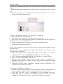
Rear view, the structure of the OET-100 PHTOMETER as following:
1 power switch: power on and power off
2 power socket: insert the power cord and connect the electronic.
3 Fuse socket: Fuse socket and power socket was complete parts, the fuse socket was
underside, move it, you can change the fuse.
4 RS232 communication port: connect with computer, transport the data
5 printer port: connect the outer printer.
There a line aeration pore set on the unit both side, when then unit running, do not
blocked the pore.
The unit inner structure included power supply, CPU, controller, driver, measure circuit
and temperature control parts.
1. Power: It’s provide +5V for logic circuit、print、LCD display, +/-5V for the
simulation circuit, +/-9.5V for PELTIER and step motor, 12V for the lamp.
2. CPU: CPU system included 8K EEPROM, 32K SRAM, I/O, real time clock etc.
3. Driver circuit: drive PELTIER and step motor.
4. Measure circuit: Measure circuit consist of photo sensor, pre amplifier, 1/8
multiplexer, A/D converter. Changed the optic signal to electric signal and digital
signal for CPU system.
5. Temperature control system: temperature controller consist of PELTIER, NTC
temperature sensor and control circuit.
The characters of BT-260 as following:
1. hermetic solid-state optical system, stable performance with low contamination of
dust and dampness, longer life time of hard membrane filters than soft ones.
2. Light split after the cuvette, corresponding every wavelength, there are
independent amplifier . Switch between different wavelength completed by electric
multiplexer, no mechanical movement, useful for bichromatic measurement.
8